Cisco C9350 Series Smart Switches Hardware Installation Guide

PDF

Front-panel components

Want to summarize with AI?

Log in

Overview

Describes the front-panel components of the Cisco C9350 switch.

This section describes the front-panel components of the Cisco C9350 series smart switches. All the switch models have similar components.

Note

The Cisco C9350 switches might have slight cosmetic differences on the bezels.
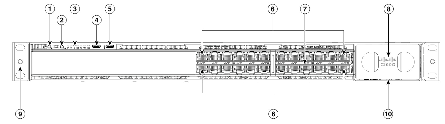
This illustration displays the front-panel of C9350-24HX
Figure 1. Front-panel of C9350-24HX

Front-panel of C9350-24HX

1

Beacon LED (UID button)

6

12x2 Multigigabit Ethernet RJ-45 ports

2

Mode button

7

Mgig port LEDs

3

Status LEDs

8

Network modules

4

USB-C console port

9

Optional RFID

5

USB-C host port

10

Network module LEDs

This illustration displays the front-panel of C9350-48HX, C9350-48HXN, and C9350-48TX.
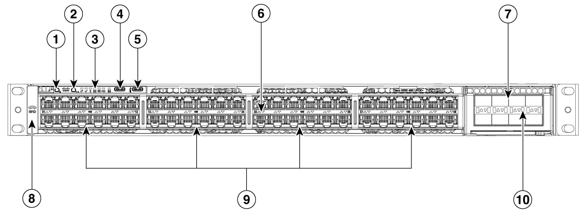
Figure 2. Front-panel of C9350-48HX, C9350-48HXN, and C9350-48TX
Front-panel of C9350-48HX, C9350-48HXN, and C9350-48TX

1

Beacon LED (UID button)

6

Mgig port LEDs

2

Mode button

7

Network modules

3

Status LEDs

8

Optional RFID

4

USB-C console port

9

24x2 Multigigabit Ethernet RJ-45 ports

5

USB-C host port

10

Network module LEDs

This illustration displays the front-panel of C9350-24P, C9350-24T, and C9350-24U.
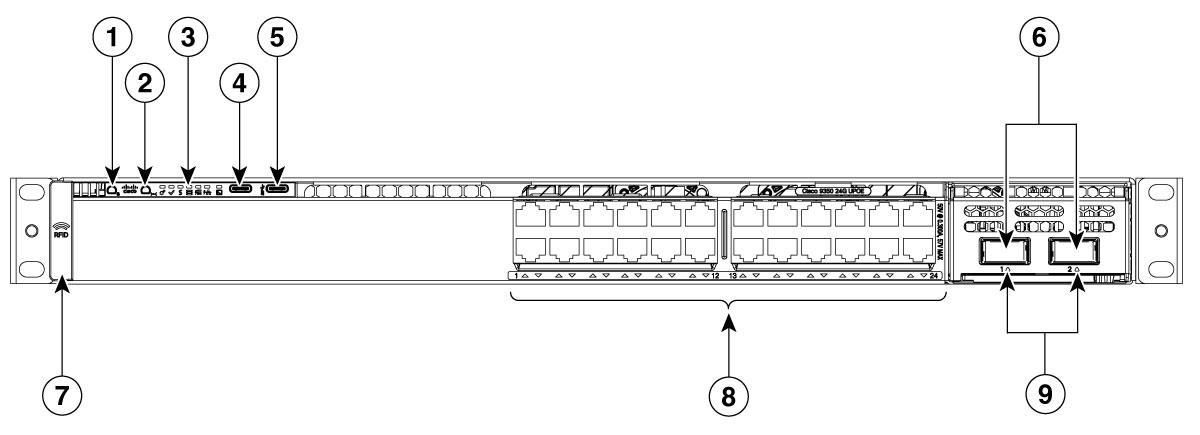
Figure 3. Front-panel of C9350-24P, C9350-24T, and C9350-24U
Front-panel of C9350-24P, C9350-24T, and C9350-24U

1

Beacon LED (UID button)

6

Network module slots

2

Mode button

7

Optional RFID

3

Status LEDs

8

12x2 1G and 10/100 M ports

4

USB-C console port

9

Network module LEDs

5

USB-C host port

-

This illustration displays the front-panel of C9350-48P, C9350-48T, and C9350-48U.
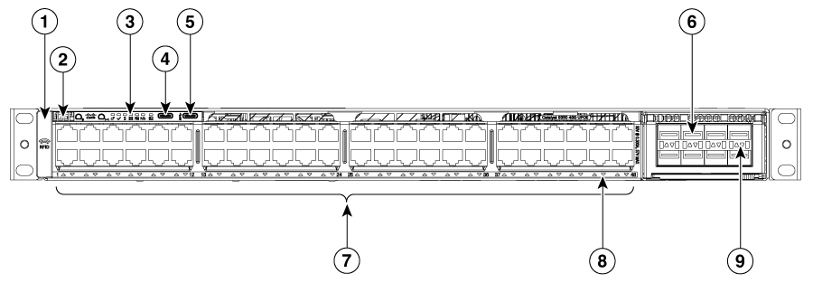
Figure 4. Front-panel of C9350-48P, C9350-48T, and C9350-48U
Front-panel of C9350-48P, C9350-48T, and C9350-48U

1

Optional RFID

6

Network modules

2

System air intake

7

24x2 1G and 10/100M ports

3

LEDs

8

Port LEDs

4

USB-C console port

9

Network module LEDs

5

USB-C host port

-

-


10/100/1000 ports

The 10/100/1000 ports are Ethernet interfaces that support multiple connection speeds. These ports use RJ-45 connectors with Ethernet pinouts. The maximum cable length is 328 feet (100 meters). The 100BASE-TX and 1000BASE-T traffic requires twisted pair (UTP) cable of Category 5 or higher. The 10BASE-T traffic can use Category 3 cable or higher.


LEDs

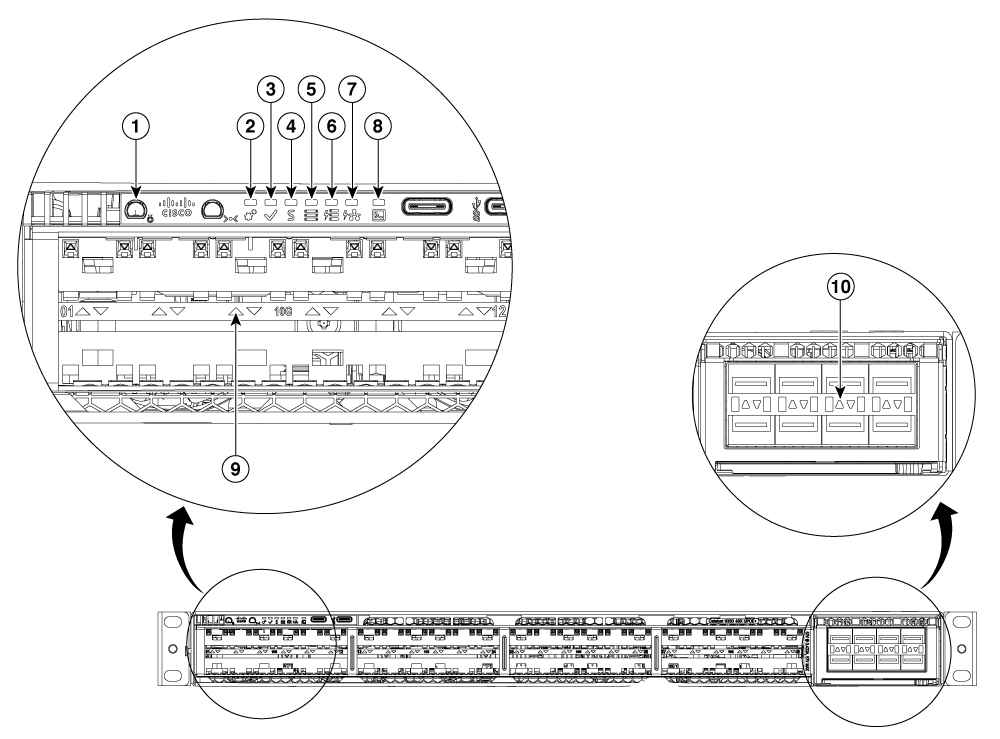
You can use the switch LEDs to monitor switch activity and its performance.

Figure 5. Switch front-panel LEDs

Front-panel LEDs of C9350

1

Beacon LED in blue (UID button)

6

S-PWR LED

2

System LED (multi-color)

7

PoE LED

3

Active LED

8

USB console LED

4

Status LED

9

Port LEDs

5

Stack LED

10

Network module LEDs


Active LEDs

This section describes the active LEDs.

Color Description

Off

Switch is not the active switch.

Green

Switch is the active switch or a standalone switch.

Blinking green

Switch is in stack standby mode.

Amber

An error occurred when the switch was selecting the active switch, or another type of stack error occurred.


Beacon LEDs

The unique device identifier (UID) and the beacon LED can be turned on by the administrator to indicate that the switch needs attention. It helps the administrator identify the switch. The beacon can be switched on by using the hw-module beacon slot 1 { on | off }command.

Table 1. Beacon LED state and description

Color/State

Description

Blue

The operator has indicated that the switch requires attention.

Off

Indicates that the module does not require any attention.


Fan LEDs

This section describes the status of fan LEDs.

Color

Description

Off

The fan is not receiving power; the fans have stopped.

Green

All fans are operating normally.

Amber

One or more fans have encountered tachometer faults.


Network module LEDs

This table describes the network module link status.

Color Description

Off

Link is off.

Green

Link is on; no activity.

Blinking green

Activity on a link; no faults.

  • The LED will blink green even when there is very little control traffic.

Amber

Link for the SFP/SFP+/SFP28 has been disabled.

Blinking amber

Link is off due to a fault or because it has exceeded a limit set in the switch software.

Caution

Link faults occur when non-compliant cabling is connected to an SFP/SFP+/SFP28 port. Use only standard-compliant cabling to connect to Cisco SFP/SFP+/SFP28 ports. You must remove from the network any cable or device that causes a link fault.


Ethernet RJ-45 network port LEDs

These LEDs indicate the status of PoE+, Cisco UPOE or Cisco UPOE+.

Table 2. Ethernet RJ-45 network port LEDs
Color Description

Off

PoE mode is not selected. None of the Ethernet RJ-45 network ports are denied power or are in a fault condition.

Green

PoE mode is selected, and the port LEDs show the PoE mode status.

Blinking amber

PoE mode is not selected. At least one of the Ethernet RJ-45 network ports are denied power, or at least one of the ports have a PoE mode fault.


Port LEDs and modes

Each Ethernet port, 1-Gigabit Ethernet module slot, and 10-Gigabit Ethernet module slot has a port LED. These port LEDs, as a group or individually, display information about the switch and about the individual ports. The port mode determines the type of information shown by the port LEDs.

To select or change a mode, press the mode button until the desired mode is highlighted. When you change port modes, the meanings of the port LED colors also change.

When you press the mode button on any switch in the switch stack, all the stack switches change to show the same selected mode. For example, if you press the mode button on the active switch to show the speed LED, all the other switches in the stack also show the speed LED.

Table 3. Port mode LEDs
Mode LED Port mode Description

STAT

Port status

The port status. This is the default mode.

SPEED

Port speed

The port operating speed: 10, 100, or 1000 Mb/s.

DUPLX

Port duplex mode

The port duplex mode: full duplex or half duplex.

ACTV

Active

The active switch status.

STACK

Stack member status

StackWise port status

Stack member status.

The StackWise port status. For more information, refer to Stack LEDs.

PoE1

The PoE+ port status.

The PoE+ port status.

1 Only switches with PoE+ ports.
Table 4. Description of switch LED colors in different modes
Port mode Port LED color Meaning

STAT (port status)

Off

No link, or port was administratively shut down.

Green

Link present, no activity.

Blinking green

Activity. Port is sending or receiving data.

Alternating green-amber

Link fault. Error frames can affect connectivity, and errors such as excessive collisions, CRC errors, and alignment and jabber errors are monitored for a link-fault indication.

Amber

Port is blocked by Spanning Tree Protocol (STP) and is not forwarding data.

After a port is reconfigured, the port LED can be amber for up to 30 seconds as STP checks the switch for possible loops.

Blinking amber

Port is blocked by STP and is only receiving control frames.

SPEED

10/100/1000/2500/5000/10000Mb/s SFP ports

Off

Port is operating at 10 Mb/s.

Green

Port is operating at 100 Mb/s.

Single green flash (on for 100 ms, off for 1900 ms)

Port is operating at 1000 Mb/s.

Blinking twice

Port is operating at 2500, 5000 or 10000 Mb/s

Network module slots

Off

Port is not operating.

Blinking green

Port is operating at up to 10 Gb/s.

DUPLX (duplex)

Off

Port is operating in half duplex.

Green

Port is operating in full duplex.

ACTV (data active switch)

Off

The switch is not the active switch.

Note
For a standalone switch, this LED is off.

Green

The switch is the active switch.

Amber

Error during active switch election.

Blinking green

Switch is a standby member of a data stack and assumes active responsibilities if the current active switch fails.

STACK (stack member)

Off

No stack member corresponding to that member number.

Blinking green

Stack member number.

PoE+2

Off

PoE+ is off.

If the powered device is receiving power from an AC power source, the port LED is off even if the device is connected to the switch port.

Green

PoE+ is on. The port LED is green when the switch port is providing power.

Alternating green-amber

PoE+ is denied because providing power to the powered device will exceed the switch power capacity.

Blinking amber

PoE+ is off due to a fault or because it has exceeded a limit set in the switch software.

Caution

PoE+ faults occur when noncompliant cabling or powered devices are connected to a PoE+ port. Use only standard-compliant cabling to connect Cisco prestandard IP Phones and wireless access points or IEEE 802.3af-compliant devices to PoE+ ports. You must remove from the network any cable or device that causes a PoE+ fault.

Amber

PoE+ for the port has been disabled.

Note
PoE+ is enabled by default.
2 Only switches with PoE+ ports.

Stack LEDs

The stack LED shows the sequence of member switches in a stack. Up to eight switches can be members of a stack. The first eight port LEDs show the member number of a switch in a stack.

When you press the Mode button to select the STACK LED, the corresponding port LEDs will blink green for each switch. For example, for switch 1 in the stack, port 1 will blink green and the rest of the LEDs will be off. On switch 2, port 2 will blink green and the rest of the LEDs will be off. The same behavior will be seen with the remaining switches in the stack.


StackPower LEDs

This section describes the StackPower LEDs, which indicates the status of the power supply unit (PSU) in the device.

Table 5. StackPower LEDs
Color Description

Off

StackPower cable is not connected, or the switch is in standalone mode.

Green

Each StackPower port is connected to another switch.

Blinking green

This appears on the switch in a StackPower ring configuration that detects an open ring or has only one StackPower cable connected.

Amber

There is a fault: load shedding is occurring, a StackPower cable is defective, or an administrative action is required. See the switch software configuration guide for information about configuring StackPower.

Blinking amber

The StackPower budget is not sufficient to meet current power demands.


System LEDs

This section describes the system LEDs.

Color

System status

Off

System is not powered on.

Green

System is operating normally.

Note

This LED tend to look more Yellow or Amber than Green when operating normally.

Blinking green

System is loading the software.

Amber

System is receiving power but is not functioning properly.

The failure is either because of

  • fan failure, or

  • system POST failure.


USB console LEDs

The USB console LED indicates whether there is an active USB connection to the port.

Table 6. USB console LED

LED

Color

Description

USB console port

Green

USB console port is active.

Off

USB is disabled.


Management ports

Management ports connect the switch to a PC running Microsoft Windows or to a terminal server.

Management ports on Cisco C9350 series smart switches are

  • Ethernet management port

  • RJ-45 console port (EIA/TIA-232), and

  • USB Type C console port.

The 10/100/1000/2.5G Ethernet management port connection uses a standard RJ-45 crossover or straight-through cable. The RJ-45 console port connection uses a RJ-45-to-DB-9 female cable. The USB console port connection uses a USB Type C to Type C or Type C to Type A cable. The USB console interface speeds are the same as the RJ-45 console interface speeds.

The console output always goes to both the RJ-45 and the USB console connectors, but the console input is active on only one of the console connectors at a time. The USB console takes precedence over the RJ-45 console. When a cable is connected into the USB console port, the RJ-45 console port becomes inactive. Conversely, when the USB cable is disconnected from the USB console port, the RJ-45 port becomes active.

You can use the CLI to configure an inactivity timeout which reactivates the RJ-45 console if the USB console has been activated and no input activity has occurred on the USB console for a specified time.

After the USB console deactivates due to inactivity, you cannot use the CLI to reactivate it. Disconnect and reconnect the USB cable to reactivate the USB console.


Multigigabit Ethernet ports

The Multigigabit or mGig Ethernet ports can be configured to auto-negotiate multiple speeds on switch ports. The ports support100 Mbps, 10 Mbps, 5 Gbps, 2.5 Gbps, and 1 Gbps speeds on Category 5E (Cat5E), and up to 10 Gbps on Category 6 (Cat6) and up to a maximum of 100 Mbps on Category 6A (Cat6A) cables.

10Gbps over Cat6 cable is limited to distances up to 55 m. For 10GBASE-T, Cat6A can support up to 100 m when transmitting 10Gbps.

Due to the extra bandwidth requirements from cables, additional limitations exist for best performance. These limitations include, but are not limited to cable reach, cable bundling parameters (tightness, frequency, number of cables, speed with respect to each cable), and cable termination quality.

The 802.3 channel requirements for interoperability typically limit the cable reach to 100 m, but other factors can shorten this reach. In addition, for both Cisco UPOE and Cisco UPOE+, and data integrity, the 100 m should not include more than 10 m of total stranded or patch cable. Therefore, the assumption is that a 100 m link includes a maximum of two 5 m patch cables of the appropriate category, and 90 m of plenum or riser (that is, solid copper core) cables. Ensure that you follow the TIA guidance on cable dressing.

It is recommended to test the complete link using an appropriate cable tester for both 10 Gbps and 5 Gbps links. However, even if the link passes the cable testing, it is still prone to occasional errors due to aggressors in the bundle, and physical disturbances of the cables.

As an example of bundling limitations, for 5 Gbps with Cat5E cable, only a total 45 m bundled length is supported; the remaining 55 m should be unbundled. For bundling, follow the Cisco Guidelines and Best Practices for the Installation and Maintenance of Data Networking Equipment, which recommends the use of Velcro ties for every 1 to 2 m bundled sections.

When you are upgrading the network gear, but reusing the existing cable plant, note that at speeds above 2.5 Gbps traditional Cat5E channel specifications do not support a full 100 m reach. To ensure 5 Gbps link speeds, we recommend using Cat6A cabling. For more information, refer to the Whitepaper from NBASE-T alliance, which has now merged with Ethernet Alliance, archived at https://archive.nbaset.ethernetalliance.org/library/white-paper-2/.


PoE, PoE+, Cisco UPoE, and Cisco UPoE+ ports

A PoE (Power over Ethernet) port is an Ethernet interface that supplies power to connected devices over the same cable used for data transmission. A PoE+ port, also known as IEEE 802.3at, provides higher power to connected devices. It can supply up to 30W of power per port. The PoE port also supports BT 2-pair mode or IEEE 802.3bt (also known as PoE++ or Type 3/4 PoE) to deliver power using only two pairs of wires in an Ethernet cable, as an alternative to its advanced four-pair power delivery.

Universal Power over Ethernet (UPoE) can supply power up to 60W per port to connected devices. UPoE+ enables the powering of high-wattage devices through Ethernet cables; it can provides up to 90W of power per switch interface.

The PoE+, UPoE, and UPoE+ ports use the same connectors as described in 10/100/1000 ports.

This section lists the specifications and features of these ports.

  • PoE+ ports: Support for IEEE 802.3af-compliant powered devices (up to 15.4 W PoE per port) and support for IEEE 802.3at-compliant powered devices (up to 30 W PoE+ per port). The maximum total PoE power in a 1RU switch is 1440W.

  • Cisco UPoE ports: Support for Type 1 (IEEE 802.3af), Type 2 (IEEE 802.3at), Type 3 (IEEE 802.3bt), and Cisco UPoE powered devices delivering up to 60 W PoE per port. The maximum total PoE power in a 1RU switch is 2880W.

  • Cisco UPoE+ ports: Support for Type 1 (IEEE 802.3af), Type 2 (IEEE 802.3at), Type 3 (IEEE 802.3bt), Type 4 (IEEE 802.3bt), and Cisco UPoE powered devices delivering up to 90 W per port. The maximum total PoE power in a 1RU switch is 4320W.

  • Configuration for StackPower: When the switch internal power supply modules cannot support the total load, StackPower configurations allow the switch to leverage power available from other switches.

  • Configurable support for Cisco intelligent power management, including enhanced power negotiation, power reservation, and per-port power policing.

Refer to the Power supply modules for the power supply matrix that defines the available PoE, PoE+ and Cisco UPoE/UPoE+ power per port. The output of the PoE+ or Cisco UPoE/UPoE+ circuit has been evaluated as a Limited Power Source (LPS) per IEC 60950-1.


Optional RFID

The chassis has an optional built-in, front-facing, passive Radio Frequency Identification (RFID) tag that uses Ultra High Frequency (UHF) RFID technology and requires an RFID reader with compatible software. It provides auto-identification capabilities for asset management and tracking. The RFID tags are compatible with the Generation 2 GS1 EPC Global Standard and are ISO 18000-6C compliant. They operate in the 860- to 960-MHz UHF band. For more information, see Radio Frequency Identification (RFID) on Cisco Catalyst 9000 Family Switches White Paper.

For Cisco C9350 series smart switches, the RFID tag is optional. Based on your requirements, you can choose to order the switch with or without an RFID tag at the time of purchase through the PID.


Network modules

The Cisco C9350 series smart switches support replaceable network modules. The switch generates logs when you insert or remove a network module with SFP/SFP+/SFP28 and QSP/QSFP28 ports.

This table lists the optional Cisco C9350 network modules.

Table 7. Network modules
Network module Description

C9350-NM-2C

This module has two 40 GE/100 GE slots with a QSFP28 connector in each slot.

C9350-NM-4C

This module has four 40 GE/100 GE slots with a QSFP28 connector in each slot.

C9350-NM-8Y

This module has eight 1/10/25 GE or four 50 GE slots with an SFP56 port in each slot.

Note

All network modules are hot-swappable.

This table lists the network modules supported by the Cisco C9350 SKUs.

Table 8. Supported network modules

Network module

Switch model

C9350-NM-2C

C9350-24HX, C9350-48HX, C9350-48HXN, C9350-24P, C9350-48P, C9350-24T, C9350-48T, C9350-48TX, C9350-24U, and C9350-48U

C9350-NM-4C

C9350-48HX, and C9350-48TX

C9350-NM-8Y

C9350-24HX, C9350-48HX, C9350-48HXN, C9350-24P, C9350-48P, C9350-24T, C9350-48T, C9350-48TX, C9350-24U, and C9350-48U


USB Type C ports

The USB Type C ports provide access to external USB flash devices (also known as thumb drives or USB keys). The USB Type C port supports flash drives with capacities from 128 MB to 256 GB.

Cisco C9350 series switches support both USB-C console port and host port.

  • The USB-C console port

    • Serves as a serial console interface for device management.

    • Connects a computer or terminal directly to the Cisco device for configuration purposes.

    • Enables terminal communication to configure routers, switches, firewalls, or other Cisco network devices.

  • The USB-C host port

    • Connects USB devices such as flash drives or hardware tokens.

    • Functions as a host to manage connected peripherals.

    • Can be used for data transfer, storage expansion, or authentication devices.

In a switch stack, you can upgrade all switches in the stack with a USB key inserted in any switch member within the stack. Cisco IOS XE software enables the flash drive with standard file system access such as read, write, erase, and copy, and the ability to format the flash device with a File Allocation Table (FAT) file system.

These ports enable you to automatically upgrade the internal flash with the USB drive's configuration and image for emergency switch recovery using USB auto-upgrade. This feature checks the internal flash for a bootable image and configuration and if either image or the configuration is not available, then the USB drive is checked for boot images and configuration. If the boot image and configuration are available, these are copied to the flash for a reboot.