How to create a switch data stack with your Cisco C9350 switch.
Cisco C9350 switches can share bandwidth by using data stacking. This table lists the supported stacking options.
Table 1. Supported stacking option
Switch model
Stacking option
Supported bandwidth
Number of members
Supported stack members
Cisco C9350 series smart switches
StackWise-1.6T
1.6 Tbps
Up to a maximum of eight
Stacks with other Cisco C9350 models at StackWise-1.6T speeds with same license level
Data stack guidelines
Refer to these guidelines before you connect the switches into a stack.
Size of the switch and any optional power supply module: The 1600 W power supply module is longer than the other modules. Stacking switches with the same power supply modules together makes it easier to cable the switches.
Length of cable: Depending on the configurations that you have, you might need different sized cables. If you do not specify the length of the StackWise cable, the 0.5 meter cable is supplied. If you need the 1 meter cable or the 3 meter cable, you can order it from your Cisco supplier. For cable part numbers, see StackWise accessories section. The Data stack cabling configurations provides examples of recommended configurations.
Data stack cabling configurations
This is an example of a recommended data stacking configuration that uses the supplied 0.5-meter StackWise cable. In this example, the switches are stacked in a vertical rack or on a table. This example shows a full-ring configuration that provides redundant connections.
Figure 1. Data stacking the switches using the 0.5-meter StackWise cables
This example shows a configuration when the switches are mounted side-by-side. Use the 1-meter and the 3-meter StackWise cables to connect the switches. This configuration provides redundant connections.
Figure 2. Side-by-side mounting of data stack
Data stack bandwidth and partitioning
This section provides examples of data stack bandwidth and possible data stack partitioning.
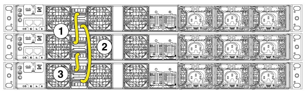
This figure shows a data stack of switches that provides full bandwidth and redundant StackWise cable connections.
Figure 3. Example of a data stack with full bandwidth connections
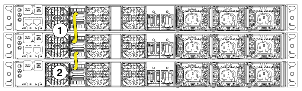
This figure shows a switch stack with incomplete StackWise cabling connections. This stack provides only half-bandwidth and does not have redundant connections.
Figure 4. Example of a data stack with half-bandwidth connections
This sections describes data stacks of switches with failover conditions.
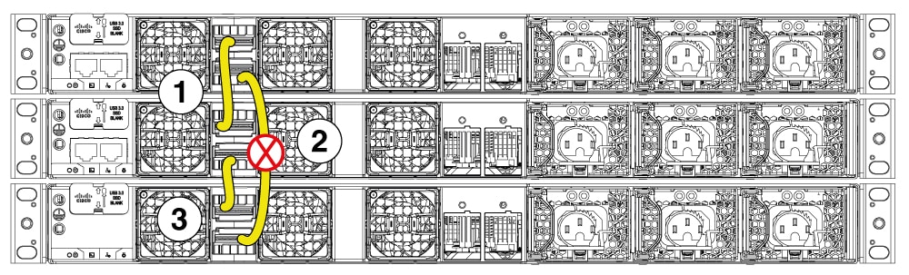
In this figure, the StackWise cable is faulty in link 2. Therefore, this stack provides only half bandwidth and does not have redundant connections.
Figure 5. Example of a data stack with a failover condition
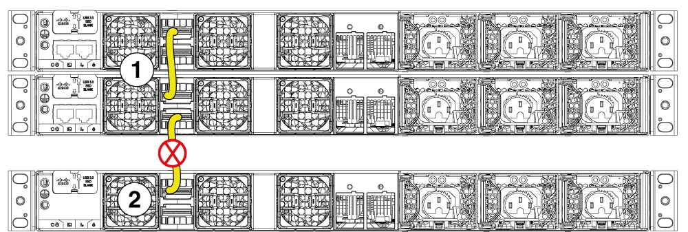
In this figure, link 2 is faulty. Therefore, this stack partitions into two stacks. Top two switches form one stack and the bottom switch become the single active switch. If the bottom switch was a member of the stack previously, (not active or standby switch), it will reload to become active.
Figure 6. Example of a partitioned data stack with a failover condition
Power-on sequence for switch stacks
Consider these guidelines before you power on the switches in a stack.
The sequence in which the switches are first powered on might affect the switch that becomes the stack master.
You can elect an active switch either by
configuring the highest priority for the switch among all other switches in the stack.
or, by powering on that switch first.
This switch remains the active switch until a reelection is required. Power on the other switches in the stack, two minutes after powering on the active switch.
If you have no preference as to which switch becomes the active switch, power on all the switches in the stack within 180 seconds. Only stack members that are powered on within the same 180-second timeframe from the initial power-on of the stack can participate in the active switch election and have a chance to become the active switch. Stack members powered on after this window will join the stack as regular members and will not participate in the initial election.
Among the switches with same priority, the switch with the lowest MAC address becomes the active switch.
To avoid service disruptions, do not add a powered-on or active switch to an existing, operational switch stack.
Follow this procedure to avoid service disruptions.
Ensure that the new switch is powered down before physically adding it to the stack.
Connect the stack cables between the new switch and the existing stack members.
Power on the new switch only after all cabling is complete.
Note
Adding an active switch directly to a live stack can disrupt operations, potentially causing the entire stack to reload - especially if the new switch has a higher stack priority or lower MAC address.