Cisco C9350 Series Smart Switches Hardware Installation Guide

PDF

Install and remove power supply modules

Want to summarize with AI?

Log in

Overview

This section provides instructions to install and reinsert power supply modules when the switch is operational.

Cisco C9350 series smart switches are shipped with preinstalled power supply modules. This section describes how to remove and install a power supply module.

Power supply install guidelines

Adhere to these guidelines when removing or installing a power supply or fan module.

  • Do not force the power supply into the slot. This can damage the pins on the switch if they are not aligned with the module.

  • A power supply that is only partially connected to the switch can disrupt the system operation.

  • Remove power from the power-supply module before removing or installing the module.

  • The power supply is hot-swappable. In some configurations, such as full PoE+ or power sharing mode, removing a power supply causes powered devices to shut down until the power budget matches the input power of a single power supply. To minimize network interruption, hot swap the power supply under these circumstances:

    • the switch is in StackPower mode and sufficient power is available, or

    • the switch is powered by other switches in a power stack, and no active backup is in progress.

    For more information, see the Stacking document.

Caution

Do not operate the switch with a power-supply module slot empty. For proper chassis cooling, all module slots must be populated, with either a power supply or a blank module.

Take note of the following safety warnings:

Warning

Statement 1024—Ground Conductor

This equipment must be grounded. To reduce the risk of electric shock, never defeat the ground conductor or operate the equipment in the absence of a suitably installed ground conductor. Contact the appropriate electrical inspection authority or an electrician if you are uncertain that suitable grounding is available.

Warning

Statement 1029—Blank Faceplates and Cover Panels

Blank faceplates and cover panels serve three important functions: they reduce the risk of electric shock and fire, they contain electromagnetic interference (EMI) that might disrupt other equipment, and they direct the flow of cooling air through the chassis. Do not operate the system unless all cards, faceplates, front covers, and rear covers are in place.


Replace and install an AC power supply

Before you begin

Warning

Statement 1028—More Than One Power Supply

This unit might have more than one power supply connection. To reduce risk of electric shock, remove all connections to de-energize the unit.

Note

A power supply must always be installed in slot A; it is the default power supply.

Procedure

1.

Turn off the power at its source.

2.

Remove the power cord from the power cord retainer.

3.

Remove the power cord from the power connector.

4.

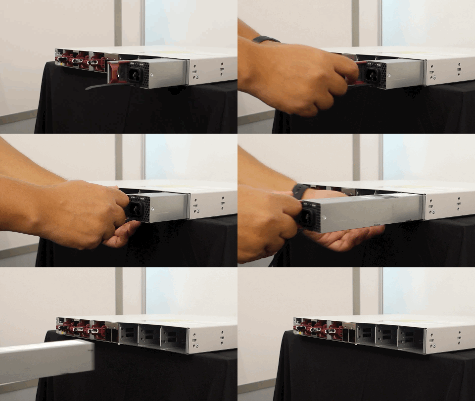
Hold the handle on the left side of the power supply module and slide the power supply out.

Figure 1. Slide the power supply out of the switch
lide the power supply out of the switch

To view the animation in PDF, click this link.

Caution
Do not leave the power-supply slot open for more than 90 seconds while the switch is operating.
5.

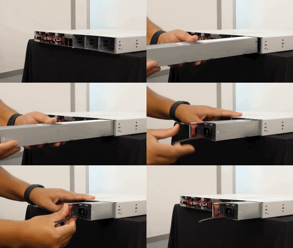
Insert the new power supply module into the power supply slot, and gently push it in. When correctly inserted, the 500 W and 850 W power supplies (excluding the power cord retainer) are flush with the switch rear panel. The 1600 W power supply modules extend 1.5 inches from the switch rear panel.

Figure 2. Insert an AC power supply
Insert an AC power supply

To view the animation in PDF, click this link.

6.

(Optional) Use the cable-tie retainer clip on the 1600 W supply.

7.

Connect the power cord to the power supply and to an AC power outlet. Switch on the power at the power source.

Add the power cord to the retainer clip.

8.

Confirm that the power supply AC OK and PS OK LEDs are green.


Find the power supply serial number

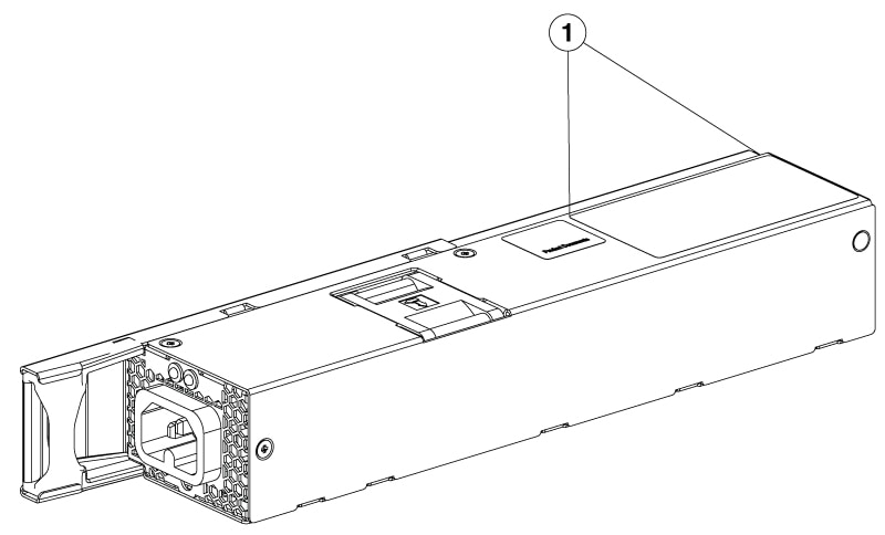
To contact Cisco Technical Assistance regarding a power supply module, you need to know the serial number. See the following illustrations to find the serial number. You can also use the CLI to find out the serial number.

Figure 3. Power supply serial number

Power supply serial number

1

Serial number location