Provides the workflow and available methods for configuring service chaining using templates and CLI commands.
This section describes the workflow and available methods for configuring service chaining for a device managed by Cisco Catalyst SD-WAN.
Workflow for service chaining configuration
Access service devices through a specific VRF. In the VPN template that corresponds to the VRF for a service device, configure service chaining and specify the service type and device addresses. By default, the tracking feature adds each service device status update to the service log. You can disable this in the VPN template.
Attach the VPN template to the device template for the device managed by Cisco Catalyst SD-WAN.
Apply the device template to the device.
Use one of these methods to configure service chaining:
Configure service chaining for Cisco IOS XE Catalyst SD-WAN devices using CLI commands
This section explains how to configure service chaining on Cisco IOS XE Catalyst SD-WAN devices using CLI commands and compares the process with Cisco SD-WAN Manager configuration.
Service chaining configuration comparison for Cisco IOS XE Catalyst SD-WAN devices using CLI commands
This table shows how configuration of service chaining by CLI corresponds to configuration in Cisco SD-WAN Manager. CLI configuration differs between Cisco IOS XE Catalyst SD-WAN devices and Cisco vEdge devices. The CLI example below is for a Cisco IOS XE Catalyst SD-WAN device.
Table 1. CLI and Cisco SD-WAN Manager service chaining configuration comparison
CLI (Cisco IOS XE Catalyst SD-WAN device)
Cisco SD-WAN Manager
service firewall vrf 10
In Cisco SD-WAN Manager, configure service insertion in the VPN template for a specific VRF—VRF 10 in this example.
Select the service type from the drop-down list; firewall in this example.
no track-enable
Note
Default: enabled
When adding a service in the VPN template Service, select On or Off for Tracking.
ipv4 address 10.0.2.1 10.0.2.2
In the VRF template Service, enter one or more IP addresses for the service device providing a specific service.
CLI example
sdwan
  service firewall vrf 10
  ipv4 address 10.0.2.1 10.0.2.2
commit
Configure service chaining using templates
Configure service chaining for a device by creating and modifying a VPN template. This allows you to define service devices and their properties for integration into the network.
Procedure
In Cisco SD-WAN Manager, create a VPN template.
Click Service.
In the Service section, click New Service and configure the following:
Service Type: Select the type of service that the service device is providing.
IP Address: IP Address is the only working option.
IPv4 Address: Enter between one and four addresses for the device.
Tracking: Determines whether the periodic health updates of the service device are recorded in the system log. Default: On
Maximum number of services: 8
Click Add. The service appears in the table of configured services.
Service chain configuration examples
Service chaining control policies direct data traffic to service devices located in various places in the network before the traffic is delivered to its destination. This section provides configuration examples for implementing service chaining using centralized control policies on the Cisco SD-WAN Controller, and configuring service devices on the device collocated in the same site. To ensure services are advertised to the Cisco SD-WAN Controller, the IP address of the service device must resolve locally.
Route intersite traffic through a service
A simple example is to route data traffic traveling from one site to another through a service. In this example, all traffic traveling from the device at Site 1 to the device at Site 2 is routed through a firewall service that sits behind a hub (system IP address 100.1.1.1). All devices are in the same VPN.
For this scenario, configure the following:
On the hub router, configure the IP address of the firewall device.
On the Cisco SD-WAN Controller, configure a control policy that redirects traffic destined from Site 1 to Site 2 through the firewall service.
On the Cisco SD-WAN Controller, apply the control policy to Site 1.
Here is the configuration procedure:
On the hub router, provision the firewall service, specifying the IP address of the firewall device. With this configuration, OMP on the hub router advertises one service route to the Cisco SD-WAN Controller. The service route contains properties that identify the location of the firewall, including the TLOC of the hub router and a service label of svc-id-1, which identifies the service type as a firewall. Before advertising the route, the device ensures that the firewall's IP address can be resolved locally.
sdwan
service firewall vrf 10
  ipv4 address 10.1.1.1
On the Cisco SD-WAN Controller, configure a control policy that redirects data traffic traveling from Site 1 to Site 2 through the firewall. Then, also on the Cisco SD-WAN Controller, apply this policy to Site 1.
policy
  lists
    site-list firewall-sites
      site-id 1
  control-policy firewall-service
    sequence 10
      match route
        site-id 2
      action accept
        set service FW vpn 10
    default-action accept
apply-policy
  site-list firewall-sites control-policy firewall-service out
This policy configuration performs the following actions:
It creates a site list called firewall-sites that the apply-policy command references and that enumerates all the sites to which this policy applies. If you later want to scale this policy so that all traffic destined for Site 2 from other sites also passes through the firewall first, you only need to add the additional site IDs to the firewall-sites site list. You do not need to change anything in the control-policy firewall-service portion of the configuration.
It defines a control policy named firewall-service with one sequence element and the following conditions:
It matches routes destined for Site 2.
If a match occurs, it accepts the route and redirects it to the firewall service provided by the hub router, which is located in VPN 10.
It accepts all nonmatching traffic, that is, all traffic not destined for Site 2.
It applies the policy to the sites listed in firewall-list, that is, to Site 1. The Cisco SD-WAN Validator applies the policy in the outbound direction, that is, on routes that it redistributes to Site 1. In these routes:
It changes the TLOC from Site 2’s TLOC to the hub router’s TLOC. The Cisco SD-WAN Controller learned this TLOC from the service route received from the hub router. Because of this TLOC change, traffic destined for Site 2 is directed to the hub router.
It changes the label to svc-id-1, which identifies the firewall service. This label causes the hub router to direct the traffic to the firewall device
.
When the hub router receives the traffic, it forwards the traffic to the address 10.1.1.1, which is the system IP address of the firewall. After the firewall finishes processing the traffic, it returns the traffic to the hub router, and the hub router then forwards it to its final destination, Site 2.
Route inter-VPN traffic through a service chain with one service per node
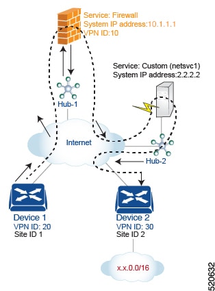
A service chain allows traffic to pass through two or more services before it reaches its destination. In this example, the configuration routes traffic from one VPN to another through services located in a third VPN. The services sit behind different hub routers. Specifically, the configuration routes all traffic from device-1 in VPN 20 that is destined for prefix x.x.0.0/16 in VPN 30 on device-2 first through the firewall behind Hub-1 and then through the custom service netsvc1 behind Hub-2 before sending it to its final destination.
For this policy to work:
VPN 10, VPN 20, and VPN 30 must be connected by an extranet, such as the Internet
VPN 10 must import routes from VPN 20 and VPN 30. Routes can be selectively imported if necessary.
VPN 20 must import routes from VPN 30. Routes can be selectively imported if necessary.
VPN 30 must import routes from VPN 20. Routes can be selectively imported if necessary.
For this scenario, you configure four things:
You configure the IP address of the firewall device on the Hub-1 router.
You configure the IP address of the custom service device on the Hub-2 router.
On the Cisco SD-WAN Controller, you configure a control policy that redirects traffic destined from Site 1 to Site 2 through the firewall device.
On the Cisco SD-WAN Controller, you configure a second control policy that redirects traffic to the custom service device.
Here is the configuration procedure:
Configure the firewall service on Hub-1. With this configuration, OMP on the Hub-1 router advertises a service route to the Cisco SD-WAN Controller. The service route contains a number of properties that identify the location of the firewall, including the TLOC of the hub router and a service label of svc-id-1, which identifies the service type as a firewall.
sdwan
service firewall vrf 10
  ipv4 address 10.1.1.1
Configure the custom service netsvc1 on Hub-2. With this configuration, OMP on the Hub-2 router advertises a service route to the Cisco SD-WAN Controller. The service route contains the TLOC of the Hub-2 and a service label of svc-id-4, which identifies the custom service.
sdwan
service netsvc1 vrf 10
  ipv4 address 2.2.2.2
Create a control policy on the Cisco SD-WAN Controller for first service in the chain, the firewall, and apply it to Site 1, which is the location of the device-1 router:
policy
  lists
    site-list firewall-custom-service-sites
      site-id 1
  control-policy firewall-service
    sequence 10
      match route
        vpn 30
        site-id 2
      action accept
        set service FW
    default-action accept
apply-policy
  site-list firewall-custom-service-sites control-policy firewall-service out
This policy configuration does the following:
Create a site list called firewall-custom-service-sites that is referenced in the apply-policy command and that enumerates all the sites that this policy applies to.
Define a control policy named firewall-service that has one sequence element and the following conditions:
Match routes destined for both VPN 30 and Site 2.
If a match occurs, accept the route and redirect it to a firewall service.
If a match does not occur, accept the traffic.
Apply the policy to the sites in the firewall-custom-service-sites site list, that is, to Site 1. The Cisco SD-WAN Controller applies this policy in the outbound direction, that is, on routes that it redistributes to Site 1. In these routes:
The TLOC is changed from Site 2’s TLOC to the Hub-1 router’s TLOC. This is the TLOC that the Cisco SD-WAN Controller learned from the service route received from the hub. It is because of the change of TLOC that traffic destined for Site 2 is directed to the Hub-1 router.
The label is changed to svc-id-1, which identifies the firewall service. This label causes the Hub-1 router to direct the traffic to the firewall device.
When the Hub-1 router receives the traffic, it forwards it to the address 10.1.1.1, which is the system IP address of the firewall. After the firewall completes processing the traffic, it returns the traffic to the Hub-1 router, which, because of the policy defined in the next step, forwards it to the Hub-2 router.
Create a control policy on the Cisco SD-WAN Controller for the second service in the chain, which is the custom service, and apply it to the site of the Hub-1 router:
policy
  site-list custom-service
    site-id 3
  control-policy netsvc1-service
    sequence 10
      match route
        vpn 30
        site-id 2
      action accept
        set service netsvc1
    default-action accept
apply-policy
  site-list custom-service control-policy netsvc1-service out
This policy configuration does the following:
Create a site list called custom-service that is referenced in the apply-policy command and that enumerates all the sites that this policy applies to.
Define a control policy named netsvc1-service that has one sequence element and the following conditions:
Match routes destined for both VPN 30 and Site 2.
If a match occurs, accept the route and redirect it to the custom service.
If a match does not occur, accept the traffic.
Apply the policy to the sites in the custom-service list, that is, to Site 3. The Cisco SD-WAN Controller applies this policy in the outbound direction, that is, on routes that it redistributes to Site 3. In these routes:
The TLOC is changed from Site 2’s TLOC to the Hub-2 router’s TLOC. This is the TLOC that the Cisco SD-WAN Controller learned from the service route received from the Hub-2 router. It is because of the change of TLOC that traffic destined for Site 2 is directed to the Hub-2 router.
The label is changed to svc-id-4, which identifies the custom service. This label causes the Hub-2 to direct the traffic to the device that is hosting the custom service
When the Hub-2 routers receives the traffic, it forwards it to the address 2.2.2.2, which is the system IP address of the device hosting the custom service. After the traffic has been processed, it is returned to the Hub-2 router, which then forwards it to its final destination, Site 2.
Route inter-VPN traffic through a service chain with multiple services per node
If a service chain has more than one service connected to the same node, meaning both services sit behind the same device, you use a combination of control policy and data policy to create the desired service chain. This example is similar to the previous one, but it places a firewall and a custom service (netsvc-1) behind a single hub router. In this scenario, the configuration routes all data traffic from device-1 in VPN 20 that is destined for prefix x.x.0.0/16 on device-2 in VPN 30 first through the firewall at Hub-1, then through the custom service netsvc1 at Hub-1, and then to its final destination.
For this policy to work:
VPN 10, VPN 20, and VPN 30 must be connected by an extranet, such as the Internet.
VPN 10 must import routes from VPN 20 and VPN 30. Routes can be selectively imported if necessary.
VPN 20 must import routes from VPN 30. Routes can be selectively imported if necessary.
VPN 30 must import routes from VPN 20. Routes can be selectively imported if necessary.
For this scenario, you configure the following:
On the hub router, you configure the firewall and custom services.
On the Cisco SD-WAN Controller, you configure a control policy that redirects data traffic from Site 1 that is destined to Site 2 through the firewall.
On the Cisco SD-WAN Controller, you configure a data policy that redirects data traffic to the custom service.
Here is the configuration procedure:
On the hub router, configure the firewall and custom services:
sdwan
service firewall vrf 10
  ipv4 address 10.1.1.1
service netsvc1 vrf 10
  ipv4 address 2.2.2.2
With this configuration, OMP on the hub router advertises two service routes to the Cisco SD-WAN Controller, one for the firewall and one for the custom service netsvc1. Both service routes include the TLOC of the Hub-1 router and a service label that identifies the service type. The firewall service uses label svc-id-1, and the custom service uses label svc-id-4.
On the Cisco SD-WAN Controller, configure a control policy controller to reroute traffic destined for VPN 30 (at Site 2) to firewall service that is connected to Hub-1 (at Site 3), and apply this policy to Site 1:
policy
  lists
    site-list device-1
      site-id 1
  control-policy firewall-service
    sequence 10
      match route
        vpn 30
      action accept
        set service FW
apply-policy
  site-list device-1 control-policy firewall-service out
On the Cisco SD-WAN Controller, configure a data policy that redirects, or chains, the data traffic received from the firewall device to the custom service netsvc1. Then apply this policy to Hub-1. This data policy routes packets headed for destinations in the network x.x.0.0/16 to the IP address 2.2.2.2, which is the system IP address of the device hosting the custom service.
When using set service action to configure active or backup control policy with set service action for service chaining, if total number of available paths (summary of active and standby paths) is more than configured send-path-limit, do not set preference directly to routes. Ensure to use set tloc-list action to set preferences together with set service action. Otherwise, you may see cases where either only active or only backup paths are advertised to a particular spoke router.
For example, in the Cisco SD-WAN Controller OMP table, there are eight active and backup paths. Based on the best-path calculation, the paths are sorted in the following order: backup1, backup2, backup3, backup4, active1, active2, active3, active4.
When send-path-limit 4 is configured, and apply the first policy, only the four backup paths are sent. If you apply the second policy, two active and two backup paths are sent.
This example shows a policy that can fail if the send-path-limit is lower than the total number of active and backup paths.
control-policy SET_SERVICE_ACTIVE-BACKUP
  sequence 10
   match route
    prefix-list _AnyIpv4PrefixList
    site-list   HUBS_PRIMARY
    tloc-list   INTERNET_TLOCS
   !
   action accept
    set
     preference 200
     service FW vpn 10
    !
   !
  !
  sequence 20
   match route
    prefix-list _AnyIpv4PrefixList
    site-list   HUBS_SECONDARY
    tloc-list   INTERNET_TLOCS
   !
   action accept
    set
     preference 100
     service FW vpn 10
    !
   !
  !
  default-action accept
!
!
This example shows the same policy after applying the recommended fix:
policy
lists
  tloc-list HUBS_PRIMARY_INTERNET_TLOCS
   tloc 10.0.0.0 color biz-internet encap ipsec preference 200
   tloc 10.0.0.1 color biz-internet encap ipsec preference 200
  !
  tloc-list HUBS_SECONDARY_INTERNET_TLOCS
   tloc 10.255.255.254 color biz-internet encap ipsec preference 100
   tloc 10.255.255.255 color biz-internet encap ipsec preference 100
  !
!
control-policy SET_SERVICE_ACTIVE-BACKUP_FIXED
  sequence 10
   match route
    prefix-list _AnyIpv4PrefixList
    site-list   HUBS_PRIMARY
    tloc-list   INTERNET_TLOCS
   !
   action accept
    set
     service FW vpn 10 tloc-list HUBS_PRIMARY_INTERNET_TLOCS
    !
   !
  !
  sequence 20
   match route
    prefix-list _AnyIpv4PrefixList
    site-list   HUBS_SECONDARY
    tloc-list   INTERNET_TLOCS
   !
   action accept
    set
     service FW vpn 10 tloc-list HUBS_SECONDARY_INTERNET_TLOCS
    !
   !
  !
  default-action accept
!
!