Describes how to direct network traffic to a service chain using three methods: control policy, data policy, or interface access control list for traffic steering implementation.
You can direct traffic to a service chain by using a control policy, data policy, or interface access control list.
How traffic steering using a control policy works
You can use a control policy to modify Cisco Overlay Management Routes, also referred to as vRoutes, to direct traffic to a service chain instead of the original destination.
Summary
The key components involved in traffic steering using a control policy are:
Control policy: Modifies vRoutes to redirect traffic to service chains
Service chain hub (SC-HUB1): Advertises service chain routes
Branch routers (B1, B2): Source and destination points for traffic flow
Cisco SD-WAN Controller: Processes and advertises modified routes based on control policy
Service chain (SC1): Traffic processing path applied to matching flows
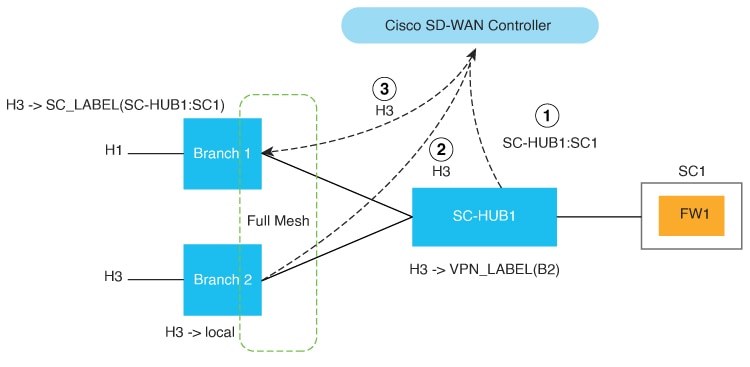
The policy causes service chain 1 (SC1) to be applied to traffic that flows between H1 (host 1) and H3 (host 3) by setting SC1 as the next hop for H1 and H3 traffic routes.
Workflow
Figure 1. Traffic Steering with a Control Policy
These stages describe how traffic steering using a control policy works:
SC-HUB1 advertises the SC1 route to make the service chain available for traffic steering.
B2 advertises the H3 route to the Cisco SD-WAN Controller to establish the original destination path.
The control policy results in overriding the H3 route next hop to SC1 and the Cisco SD-WAN Controller advertises the modified H3 route to B1.
Before the policy is in effect, traffic flows from B2 (branch 2) to B1 (branch 1). After the policy is in effect, traffic flows from B2 to SC-HUB1:SC1 to B1.
Note
Example configuration:
Control-policy name
    sequence number
        match route
        action accept
	  set service-chain sc_name [tloc|tloc-list name] [vpn vpn]
apply-policy site-list site_list control-policy name out
How data policies steer traffic
You can use a data policy to match traffic and operate in the context of source VPNs during forwarding.
Summary
The key components involved in traffic steering using data policies are:
Data policy: Matches traffic and defines forwarding actions based on specified criteria
Match criteria: Specifies applications to be matched to source and destination IP address combinations
Service chain: Defines the path for traffic processing through network services
TLOC ranking: Specifies traffic path preference using TLOC ranking
Workflow
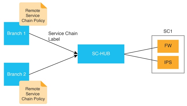
Figure 2. Traffic Steering with Traffic Service Chaining Intent Specified at a Remote Branch
These stages describe how data policies steer traffic:
The system configures the data policy with match criteria and service chaining parameters for remote branch traffic steering.
match criteria specifies applications to be matched to source and destination IP address combinations
restrict|fallback configures restrict or fall back
TLOC|TLOC-list list specifies the traffic path preference using TLOC ranking
Noteset attribute trust-posture is available from Cisco Catalyst SD-WAN Manager Release 20.14.1.
policy
 data-policy name
  vpn-list name
   sequence 100
    match criteria
    action accept
     set service-chain sc_name vpn vpn {restrict|fallback} [tloc|tloc-list list]
set attribute trust-posture {trusted | untrusted}
apply-policy site-list remote-sites data-policy name from-service
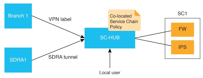
The system applies service chaining intent locally on the device to which the service chain is attached.
Figure 3. Traffic Steering with Traffic Service Chaining Intent Specified on a Local Device
In this configuration, local indicates that traffic needs to be directed to a service chain locally.
set service-chain SC1 [vpn vpn] local [restrict|fallback]
apply-policy site-list SC-HUB-sites data-policy policy {from-service|from tunnel}|from-tunnel}
Traffic steering using an interface access control list
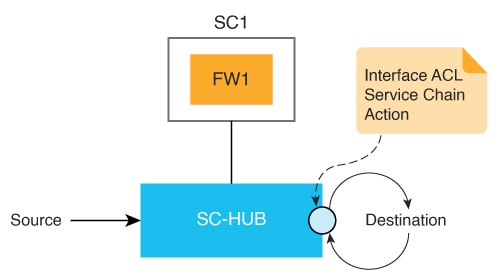
You can use an interface access control list (ACL) to service chain traffic that is incoming or outgoing on a specified interface. In some situations, the traffic forwarding decision may need to come from a prior routing lookup or data policy.
This approach is useful when all traffic from an interface should be directed through a service chain.
Summary
The key components involved in traffic steering using an interface ACL are:
Interface ACL: Controls traffic flow on specified interfaces and directs traffic through service chains
Service chain: Processes traffic according to configured policies and routing decisions
Traffic matching criteria: Determines which traffic flows are subject to service chaining
Workflow
Figure 4. Traffic Steering with an ACL
Traffic steering using an interface ACL involves the following stages:
Configure the access control list with matching criteria and service chain action.
access-list list
  sequence number
    match criteria
    action accept
     set service-chain SC1 [vpn vpn] {restrict|fallback}
Apply the access list to the interface for incoming or outgoing traffic.
interface interface
 access-list list {in|out}
The system processes traffic according to the configured ACL rules and directs matching traffic through the specified service chain.
Note
Service chaining can be used in dual-site setups using Virtual Router Redundancy Protocol (VRRP) for redundancy. Ensure your service chaining policy does not block VRRP control traffic. Service chaining policies often have a default action to drop traffic that does not meet the match criteria. This can accidentally block VRRP control packets. To prevent this, set the default action in your service chaining policy to accept VRRP control traffic. This will ensure VRRP works correctly for redundancy.