- About This Book
-
- Getting Started
- Setting Up the Prime Fulfillment Services for L2VPN
- Creating a FlexUNI/EVC Ethernet Policy
- Creating a FlexUNI/EVC Ethernet Service Request
- Creating a FlexUNI/EVC ATM-Ethernet Interworking Policy
- Creating a FlexUNI/EVC ATM-Ethernet Interworking Service Request
- Creating an L2VPN Policy
- Creating an L2VPN Service Request
- Creating a VPLS Policy
- Creating a VPLS Service Request
- Deploying, Monitoring, and Auditing Service Requests
- Using Auto Discovery for L2 Services
- Sample Configlets
- Setting Up VLAN Translation
-
- Getting Started with MPLS VPN
- Setting Up the Prime Fulfillment Services
- Independent VRF Management
- IPv6 and 6VPE Support in MPLS VPN
- MPLS VPN Service Policies
- MPLS VPN Service Requests
- Provisioning Regular PE-CE Links
- Provisioning Multi-VRFCE PE-CE Links
- Provisioning Management VPN
- Provisioning Cable Services
- Provisioning Carrier Supporting Carrier
- Provisioning Multiple Devices
- Spanning Multiple Autonomous Systems
- Sample Configlets
- Troubleshooting MPLS VPNs
Cisco Prime Fulfillment User Guide 6.1
Bias-Free Language
The documentation set for this product strives to use bias-free language. For the purposes of this documentation set, bias-free is defined as language that does not imply discrimination based on age, disability, gender, racial identity, ethnic identity, sexual orientation, socioeconomic status, and intersectionality. Exceptions may be present in the documentation due to language that is hardcoded in the user interfaces of the product software, language used based on RFP documentation, or language that is used by a referenced third-party product. Learn more about how Cisco is using Inclusive Language.
- Updated:
- March 20, 2015
Chapter: Getting Started
Getting Started
This part contains a detailed description of the Cisco Prime Fulfillment Traffic Engineering Management (TEM) product, including the various features, the GUI, and the step-by-step processes needed to perform various traffic engineering management tasks.
To get an overview of TEM and an introduction to some of the terminology used, see Cisco Prime Fulfillment Theory of Operations Guide 6.1.
This chapter describes the installation procedure for Prime Fulfillment. The general installation procedure for Cisco Prime Fulfillment (Prime Fulfillment) is described in the Cisco Prime Fulfillment Installation Guide 6.1.
This chapter includes the following sections:
•![]() Prerequisites and Limitations
Prerequisites and Limitations
–![]() Feature-Specific Prerequisites and Limitations
Feature-Specific Prerequisites and Limitations
•![]() Preconfiguration Process Overview
Preconfiguration Process Overview
–![]() Editing DCPL Properties (Optional)
Editing DCPL Properties (Optional)
Process Overview
The main components and flows in TEM are shown in Figure 35-1.
Figure 35-1 Main Process Flows in TEM
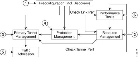
The illustration includes the following components:
1. ![]() Preconfiguration—Sets up key parameters that enable the system to collect TE network information (TE Discovery) and subsequently deploy TE configurations on the chosen network. (See Chapter 35 "Getting Started.")
Preconfiguration—Sets up key parameters that enable the system to collect TE network information (TE Discovery) and subsequently deploy TE configurations on the chosen network. (See Chapter 35 "Getting Started.")
2. ![]() Resource Management—Tuning of certain properties on the TE interfaces to optimize the tunnel placement. (See Chapter 37, "TE Resource Management.")
Resource Management—Tuning of certain properties on the TE interfaces to optimize the tunnel placement. (See Chapter 37, "TE Resource Management.")
3. ![]() Primary Tunnel Management—Create and manage primary tunnels, either unmanaged (see Chapter 38, "Basic Tunnel Management") or managed. (see Chapter 38, "Basic Tunnel Management" or Chapter 39, "Advanced Primary Tunnel Management.")
Primary Tunnel Management—Create and manage primary tunnels, either unmanaged (see Chapter 38, "Basic Tunnel Management") or managed. (see Chapter 38, "Basic Tunnel Management" or Chapter 39, "Advanced Primary Tunnel Management.")
4. ![]() Protection Management—Protect selected elements in the network (links, routers, or SRLGs) against failure. (See Chapter 39, "Advanced Primary Tunnel Management.")
Protection Management—Protect selected elements in the network (links, routers, or SRLGs) against failure. (See Chapter 39, "Advanced Primary Tunnel Management.")
5. ![]() Traffic admission—Assign traffic to traffic-engineered tunnels. (See Chapter 41, "TE Traffic Admission.")
Traffic admission—Assign traffic to traffic-engineered tunnels. (See Chapter 41, "TE Traffic Admission.")
6. ![]() Performance Tasks—Calculates interface/tunnel bandwidth utilization using the Simple Network Management Protocol (SNMP). (See Chapter 42, "Administration.")
Performance Tasks—Calculates interface/tunnel bandwidth utilization using the Simple Network Management Protocol (SNMP). (See Chapter 42, "Administration.")
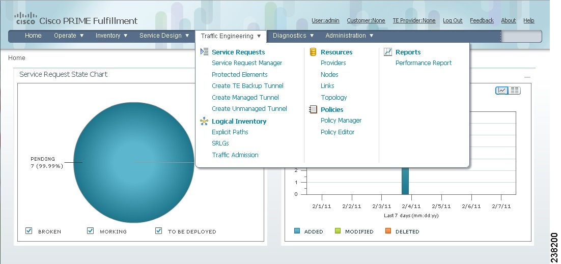
The Traffic Engineering menu options in the Prime Fulfillment user interface are shown in Figure 35-2.
Figure 35-2 Traffic Engineering Menu Options
Prerequisites and Limitations
The current release of Prime Fulfillment involves certain prerequisites and limitations, which are described in this section.
See the Cisco Prime Fulfillment Installation Guide 6.1 for general system recommendations.
General Limitations
The present release of ISC has the following limitations:
•![]() Although concurrent use of Prime Fulfillment is supported in the Planning portion of the current implementation (see the section Multiple Concurrent Users in the Cisco Prime Fulfillment Theory of Operations Guide 6.1), multiple browsers on the same machine are still not recommended due to a limitation in Browser Session Attributes.
Although concurrent use of Prime Fulfillment is supported in the Planning portion of the current implementation (see the section Multiple Concurrent Users in the Cisco Prime Fulfillment Theory of Operations Guide 6.1), multiple browsers on the same machine are still not recommended due to a limitation in Browser Session Attributes.
•![]() JRE version 1.6.0_07 or higher should be installed on the client computer for launching Java applications and Applets. This can be done via Java's Control Panel. If you do not already have Java installed, you can use the links on the Topology Tool page to install the version that is bundled with Prime Fulfillment.
JRE version 1.6.0_07 or higher should be installed on the client computer for launching Java applications and Applets. This can be done via Java's Control Panel. If you do not already have Java installed, you can use the links on the Topology Tool page to install the version that is bundled with Prime Fulfillment.
•![]() If your repository predates the ISC 4.1 release and has been upgraded to a 4.1 or later repository, you need to run a TE Discovery task to collect software version information from the devices before deploying service requests.
If your repository predates the ISC 4.1 release and has been upgraded to a 4.1 or later repository, you need to run a TE Discovery task to collect software version information from the devices before deploying service requests.
•![]() Let issued service requests finish deployment before issuing other service requests to avoid conflicts. This is described in more detail in the tunnel provisioning chapters.
Let issued service requests finish deployment before issuing other service requests to avoid conflicts. This is described in more detail in the tunnel provisioning chapters.
Feature-Specific Prerequisites and Limitations
Prime Fulfillment has the following feature-specific prerequisites and limitations:
•![]() Some features might only be available with a particular license. In addition, the number of nodes provided by the license limits the size of the network. For more information, see Licensing, page 68-6.
Some features might only be available with a particular license. In addition, the number of nodes provided by the license limits the size of the network. For more information, see Licensing, page 68-6.
•![]() A number of specific requirements are associated with the TE Discovery task. These are described in TE Discovery Prerequisites and Limitations, page 36-2.
A number of specific requirements are associated with the TE Discovery task. These are described in TE Discovery Prerequisites and Limitations, page 36-2.
•![]() Prime Fulfillment manages a single OSPF area or IS-IS level. Prime Fulfillment also supports multiple OSPF areas, however it does not discover tunnels between areas. Each OSPF area is mapped to a TE provider and is discovered area by area independently.
Prime Fulfillment manages a single OSPF area or IS-IS level. Prime Fulfillment also supports multiple OSPF areas, however it does not discover tunnels between areas. Each OSPF area is mapped to a TE provider and is discovered area by area independently.
•![]() Prime Fulfillment only supports MPLS-TE topology with point-to-point links.
Prime Fulfillment only supports MPLS-TE topology with point-to-point links.
Non-Cisco Devices and TEM
Prime Fulfillment does not manage non-Cisco devices and Prime Fulfillment cannot be used to provision them.
Prime Fulfillment will, however, discover non-Cisco devices and store them in the repository. Tunnels can be run through these devices, the bandwidth consumed can be accounted for, but the devices are not otherwise managed by Prime Fulfillment. TE tunnels originating from non-Cisco devices will not be discovered.
Sorting can be performed on different attributes in various parts of the Prime Fulfillment GUI. However, due to the added support for non-Cisco devices, sorting cannot be performed on Device Name and MPLS TE ID in the TE Nodes List window.
Supported Platforms
For supported devices and IOS platforms, see the Cisco Prime Fulfillment Installation Guide 6.1.
Error Messages
Warnings and violations that are invoked when using the TE planning tools in Prime Fulfillment are documented in Chapter 45, "Warnings and Violations."
Elixir warning messages might appear when performing deployments in Prime Fulfillment:
WARNING Elixir.ServiceBlade Unable to load support matrix for the platform or platform
family. The default support matrix is loaded instead for role: TunnelHead.
WARNING Elixir.ConfigManager Attribute - lockdown of Command - Tunnel_PathOption can NOT
be retrieved from the input SR - SKIPPING.
The deployments will, however, be successful and these messages can be safely ignored.
Preconfiguration Process Overview
The preconfiguration process sets up key parameters that enable the system to collect TE network information and subsequently deploy TE configurations on the chosen network.
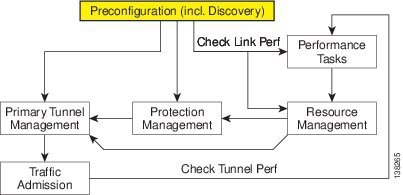
The highlighted box in Figure 35-3 shows where in Prime Fulfillment the preconfiguration steps take place.
Figure 35-3 Prime Fulfillment Process Diagram - Preconfiguration
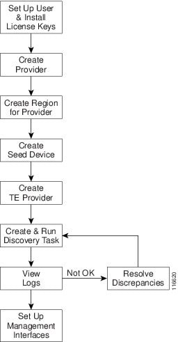
The different steps in the preconfiguration process are provided in Figure 35-4.
Figure 35-4 Preconfiguration Process
Before commencing the preconfiguration process, MPLS-TE needs to be enabled on the network devices by making sure that the IP addresses used as devices' TE IDs are accessible from the management station (this step is not supported by TEM).
The preconfiguration process includes the following steps:
1. ![]() Set up new user and install license keys—To run the TEM blade of Prime Fulfillment, it is necessary to create a new user and install license keys. These keys allows you to view and manage the TE tunnels and resources using Prime Fulfillment. (See TEM Setup and Installation)
Set up new user and install license keys—To run the TEM blade of Prime Fulfillment, it is necessary to create a new user and install license keys. These keys allows you to view and manage the TE tunnels and resources using Prime Fulfillment. (See TEM Setup and Installation)
2. ![]() Create a provider—The provider is a concept designed to allow many different operators to work on Prime Fulfillment simultaneously, each working on different networks. Thus, each provider has to be defined and used as a reference operator for future work on the system. (To create a provider, see Providers, page 5-9.)
Create a provider—The provider is a concept designed to allow many different operators to work on Prime Fulfillment simultaneously, each working on different networks. Thus, each provider has to be defined and used as a reference operator for future work on the system. (To create a provider, see Providers, page 5-9.)
3. ![]() Create a region for the provider—The region is important because a single provider could have multiple networks. The region is used as a further level of differentiation to allow for such circumstances. (To create a region, see Accessing the Provider Regions, page 5-12.)
Create a region for the provider—The region is important because a single provider could have multiple networks. The region is used as a further level of differentiation to allow for such circumstances. (To create a region, see Accessing the Provider Regions, page 5-12.)
4. ![]() Create a seed device—This IOS or IOS XR device will be the seed router for TE Discovery. The network discovery process uses the seed router as an initial communication point to discover the MPLS TE network topology. (To create a seed router, see Devices, page 4-1.)
Create a seed device—This IOS or IOS XR device will be the seed router for TE Discovery. The network discovery process uses the seed router as an initial communication point to discover the MPLS TE network topology. (To create a seed router, see Devices, page 4-1.)
5. ![]() Create a TE Provider—Providers can be defined as TE provider, if they are supporting MPLS TE in their network. To enable a TE network to be managed, it is necessary to create a TE provider. All TE related data associated with a given network is stored under a unique TE provider. A provider and region uniquely define a TE provider (See Creating a TE Provider.)
Create a TE Provider—Providers can be defined as TE provider, if they are supporting MPLS TE in their network. To enable a TE network to be managed, it is necessary to create a TE provider. All TE related data associated with a given network is stored under a unique TE provider. A provider and region uniquely define a TE provider (See Creating a TE Provider.)
6. ![]() Run a TE Discovery Task—Discover the TE network for a particular TE provider to populate the repository with a view to creating primary and backup tunnels. (See Chapter 36, "TE Network Discovery".)
Run a TE Discovery Task—Discover the TE network for a particular TE provider to populate the repository with a view to creating primary and backup tunnels. (See Chapter 36, "TE Network Discovery".)
7. ![]() Set Up Management Interfaces—Set up management interfaces for discovered devices or update server host file with resolution for all discovered devices. This step is only necessary if the devices in the TE network are not accessible via their hostnames (See Setting Up Management Interfaces, page 36-11.)
Set Up Management Interfaces—Set up management interfaces for discovered devices or update server host file with resolution for all discovered devices. This step is only necessary if the devices in the TE network are not accessible via their hostnames (See Setting Up Management Interfaces, page 36-11.)

Note ![]() If Telnet is selected to communicate with the seed router, Telnet must also be used for the other network devices. Likewise, if SSH is selected for the seed router, SSH must be used for all other devices.
If Telnet is selected to communicate with the seed router, Telnet must also be used for the other network devices. Likewise, if SSH is selected for the seed router, SSH must be used for all other devices.
TEM Setup and Installation
Before setting up Prime Fulfillment, the Prime Fulfillment software must be installed. To do so, see the Cisco Prime Fulfillment Installation Guide 6.1.
To set up a new Prime Fulfillment user, one or more users with a TE role must be created. For step by step instructions, see Users, page 70-2.
Licensing information, including the Prime Fulfillment licensing options and the procedure needed to install licenses is described in Licensing, page 68-6.
Editing DCPL Properties (Optional)
The Prime Fulfillment Dynamic Component Properties Library (DCPL) includes a wide variety of properties that are accessible from the GUI, some of which can be modified.
The various DCPL properties, including those pertaining to Prime Fulfillment, and the process for editing these properties are described in Manage Control Center, page 68-1.

Warning ![]() Do not attempt to modify the DCPL properties unless you fully understand the implications.
Do not attempt to modify the DCPL properties unless you fully understand the implications.
In the Prime Fulfillment GUI, the DCPL properties are found in Administration > Hosts. Check a check box for a specific host and click the Config button.
The DCPL properties pertaining to Prime Fulfillment are found in the following folders:
•![]() Provisioning > Service > TE
Provisioning > Service > TE
•![]() TE
TE
•![]() TE Topology
TE Topology
Creating a TE Provider
Before TE Discovery or any manipulation of TE data can take place, at least one TE provider has to be created. For example, an OSPF area can be assigned as a TE provider. Prior to this, a provider and a region for that provider must have been set up (see Preconfiguration Process Overview).
One region can be assigned as the default region as a place for discovered routers. These routers can then subsequently be placed in any region. For more information, see the section multiple hosts in the Cisco Prime Fulfillment Theory of Operations Guide 6.1.
To create a TE provider, use the following steps:
Step 1 ![]() Choose Traffic Engineering > Providers.
Choose Traffic Engineering > Providers.
The TE Providers window appears.
Step 2 ![]() Click Create to create a TE provider.
Click Create to create a TE provider.
The Create/Edit TE Provider window in Figure 35-5 appears.
Figure 35-5 Create/Edit TE Provider
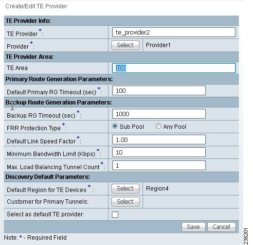
The Create/Edit TE Provider window includes the following fields:
•![]() TE Area—OSPF area assigned to the TE provider. This can be any positive integer from 0 to 4294967295 or a dot notation address of the form x.x.x.x where x is a number between 0 and 255.
TE Area—OSPF area assigned to the TE provider. This can be any positive integer from 0 to 4294967295 or a dot notation address of the form x.x.x.x where x is a number between 0 and 255.
•![]() Default Primary RG Timeout—Default computation timeout for primary tunnels.
Default Primary RG Timeout—Default computation timeout for primary tunnels.
•![]() Backup RG Timeout—Computation timeout per element for backup tunnels (for each protected element, the timer is reset to zero before the Prime Fulfillment attempts to protect it).
Backup RG Timeout—Computation timeout per element for backup tunnels (for each protected element, the timer is reset to zero before the Prime Fulfillment attempts to protect it).
•![]() FRR Protection Type—Fast Re-Route (FRR) protection type:
FRR Protection Type—Fast Re-Route (FRR) protection type:
–![]() Sub Pool—Protect only sub pool primary tunnels.
Sub Pool—Protect only sub pool primary tunnels.
–![]() Any Pool—Protect both sub pool and global pool primary tunnels.
Any Pool—Protect both sub pool and global pool primary tunnels.
For a definition of pool types, see the section on bandwidth pools in the Cisco Prime Fulfillment Theory of Operations Guide 6.1.
•![]() Default Link Speed Factor—Default multiplication factor to be applied to the link speed in order to determine move affected tunnels. that needs to be protected. The link's bandwidth is multiplied by the link speed factor, then the RSVP bandwidth reserved for the link (sub pool or global pool depending on the FRR protection type) is subtracted, and the resulting bandwidth is then available to FRR backup tunnels.
Default Link Speed Factor—Default multiplication factor to be applied to the link speed in order to determine move affected tunnels. that needs to be protected. The link's bandwidth is multiplied by the link speed factor, then the RSVP bandwidth reserved for the link (sub pool or global pool depending on the FRR protection type) is subtracted, and the resulting bandwidth is then available to FRR backup tunnels.
Interpretation of the link speed factor:
> 1.0 (overbooking)—more backup bandwidth than the link has available.
< 1.0 (underbooking)—less backup bandwidth than the link has available.
•![]() Minimum Bandwidth Limit—Minimum bandwidth allowed for backup tunnels.
Minimum Bandwidth Limit—Minimum bandwidth allowed for backup tunnels.
•![]() Max. Load Balancing Tunnel Count—This is the maximum number of backup tunnels needed to protect a flow through a protected element. Here, a flow is defined as follows:
Max. Load Balancing Tunnel Count—This is the maximum number of backup tunnels needed to protect a flow through a protected element. Here, a flow is defined as follows:
There are two flows in a protected link, one in each of the directions that traffic can flow. For a node, the number of flows depends on the number of neighbouring nodes for a particular node. There is a flow for each neighbour pair. So a node with 3 neighbours, A, B, and C, has 6 flows through it - A->B, A->C, B->A,B->C, C->A, C->B.
•![]() Default Region for TE Devices—The default provider region is the one assigned by TE Discovery to a newly discovered device. If the device already exists in the repository and has a region defined, TE Discovery keeps that setting. It is possible to change the region of a device after TE Discovery.
Default Region for TE Devices—The default provider region is the one assigned by TE Discovery to a newly discovered device. If the device already exists in the repository and has a region defined, TE Discovery keeps that setting. It is possible to change the region of a device after TE Discovery.
•![]() Customer for Primary Tunnels—Name of customer for primary TE tunnels.
Customer for Primary Tunnels—Name of customer for primary TE tunnels.
Step 3 ![]() In the TE Provider field, enter a name for the new TE provider.
In the TE Provider field, enter a name for the new TE provider.
Step 4 ![]() To select a provider to be this TE provider, click the Select button next to the Provider field.
To select a provider to be this TE provider, click the Select button next to the Provider field.
The Select Provider window appears.
Step 5 ![]() Select the desired provider using the radio buttons or search for a provider with search criteria matching a provider name and click Find.
Select the desired provider using the radio buttons or search for a provider with search criteria matching a provider name and click Find.
Step 6 ![]() Click Select to select the desired provider.
Click Select to select the desired provider.
The Select Provider window closes. The selected provider name is displayed in the Provider field.
Step 7 ![]() In the TE Area field, specify the number of the OSPF area to act as TE area.
In the TE Area field, specify the number of the OSPF area to act as TE area.
Both dot notation and decimal notation are supported for the area identifier.

Note ![]() The TE Area field can be left blank if the seed router used for TE Discovery is not an Area Border Router, and it will be automatically populated on discovery.
The TE Area field can be left blank if the seed router used for TE Discovery is not an Area Border Router, and it will be automatically populated on discovery.
Depending on the seed router used for TE Discovery, the area identifier should be set as follows:
•![]() Seed router is an ABR: The area identifier field in TE provider must be set to indicate which of the two or more areas on the ABR is to be discovered.
Seed router is an ABR: The area identifier field in TE provider must be set to indicate which of the two or more areas on the ABR is to be discovered.
•![]() Seed router is NOT an ABR: Leave blank.
Seed router is NOT an ABR: Leave blank.

Note ![]() If you do not set the Area Identifier in TE Provider, TE Discovery will set it. After it is set, it cannot be changed.
If you do not set the Area Identifier in TE Provider, TE Discovery will set it. After it is set, it cannot be changed.
Step 8 ![]() Add primary and backup route generation parameters.
Add primary and backup route generation parameters.
When the FRR (Fast Re-Route) protection type is equal to Sub Pool, the backup tunnels generated by the tool will protect only the sub pool primary tunnels. When it is equal to Any Pool, the backup tunnels generated by the tool will protect both sub pool and global pool primary tunnels.
For more information on Fast Re-Route (FRR) protection pools, see the section on bandwidth pools in the Cisco Prime Fulfillment Theory of Operations Guide 6.1.
Step 9 ![]() Fill in the remaining required fields (marked `*') and any optional fields as desired.
Fill in the remaining required fields (marked `*') and any optional fields as desired.
Step 10 ![]() For the required Default Region for TE Devices field, click the corresponding Select button.
For the required Default Region for TE Devices field, click the corresponding Select button.
The Region for Create TE Provider window appears.
Step 11 ![]() Select the desired region using the radio buttons.
Select the desired region using the radio buttons.
Step 12 ![]() Click Select to select the desired default region.
Click Select to select the desired default region.
The Region for Create TE Provider window closes. The selected region name is displayed in the Default Region for TE Devices field.
Step 13 ![]() For the optional Customer for Primary Tunnels field, click the corresponding Select button.
For the optional Customer for Primary Tunnels field, click the corresponding Select button.
The Customer for Create TE Provider window appears.
Step 14 ![]() If desired, select a customer using the radio buttons or search for a customer by entering customer search criteria in the Show Customers with Customer Name matching field and click Find.
If desired, select a customer using the radio buttons or search for a customer by entering customer search criteria in the Show Customers with Customer Name matching field and click Find.
Step 15 ![]() Click Select to select the desired customer.
Click Select to select the desired customer.
The Select Customer for Create TE Provider window closes. The selected customer name is displayed in the Customer for Primary Tunnels field of the Create/Edit TE Provider window.
Step 16 ![]() Click Save.
Click Save.
The created TE provider appears in the TE Provider window and can now be used to perform TE discovery and other TE functions.
To switch between TE providers, go to the to the top of the Prime Fulfillment window above the menu toolbar (Figure 35-2) and click the TE Provider link.
 Feedback