- About This Book
-
- Getting Started
- Setting Up the Prime Fulfillment Services for L2VPN
- Creating a FlexUNI/EVC Ethernet Policy
- Creating a FlexUNI/EVC Ethernet Service Request
- Creating a FlexUNI/EVC ATM-Ethernet Interworking Policy
- Creating a FlexUNI/EVC ATM-Ethernet Interworking Service Request
- Creating an L2VPN Policy
- Creating an L2VPN Service Request
- Creating a VPLS Policy
- Creating a VPLS Service Request
- Deploying, Monitoring, and Auditing Service Requests
- Using Auto Discovery for L2 Services
- Sample Configlets
- Setting Up VLAN Translation
-
- Getting Started with MPLS VPN
- Setting Up the Prime Fulfillment Services
- Independent VRF Management
- IPv6 and 6VPE Support in MPLS VPN
- MPLS VPN Service Policies
- MPLS VPN Service Requests
- Provisioning Regular PE-CE Links
- Provisioning Multi-VRFCE PE-CE Links
- Provisioning Management VPN
- Provisioning Cable Services
- Provisioning Carrier Supporting Carrier
- Provisioning Multiple Devices
- Spanning Multiple Autonomous Systems
- Sample Configlets
- Troubleshooting MPLS VPNs
Cisco Prime Fulfillment User Guide 6.1
Bias-Free Language
The documentation set for this product strives to use bias-free language. For the purposes of this documentation set, bias-free is defined as language that does not imply discrimination based on age, disability, gender, racial identity, ethnic identity, sexual orientation, socioeconomic status, and intersectionality. Exceptions may be present in the documentation due to language that is hardcoded in the user interfaces of the product software, language used based on RFP documentation, or language that is used by a referenced third-party product. Learn more about how Cisco is using Inclusive Language.
- Updated:
- March 20, 2015
Chapter: MPLS VPN Service Requests
- Service Enhancements
- How Prime Fulfillment Accesses Network Devices
- Examples of Creating MPLS VPN Service Requests
- Migrating PE Devices from IOS to IOS XR
MPLS VPN Service Requests
This chapter contains the following sections:
•![]() How Prime Fulfillment Accesses Network Devices
How Prime Fulfillment Accesses Network Devices
•![]() Examples of Creating MPLS VPN Service Requests
Examples of Creating MPLS VPN Service Requests
•![]() Migrating PE Devices from IOS to IOS XR
Migrating PE Devices from IOS to IOS XR
To apply MPLS VPN policies to network devices, you must deploy the service request. When you deploy a service request, Prime Fulfillment compares the device information in the Repository (the Prime Fulfillment database) with the current device configuration and generates a configlet. Additionally, you can perform various monitoring and auditing tasks on service requests. These common task that apply to all types of Prime Fulfillment service requests are covered in Chapter 47, "Managing Service Requests". See that chapter for more information on these tasks.
Service Enhancements
With this release of MPLS VPN Management, a number of enhancements to the service function are available:
•![]() A service is no longer limited to a single PE-CE link at a time. Under Prime Fulfillment, a service can be comprised of multiple PE-CE links per service request.
A service is no longer limited to a single PE-CE link at a time. Under Prime Fulfillment, a service can be comprised of multiple PE-CE links per service request.
•![]() Multicast MPLS VPNs
Multicast MPLS VPNs
A multicast address is a single address that represents a group of machines. Unlike a broadcast address, however, the machines using a multicast address have all expressed a desire to receive the messages sent to the address. A message sent to the broadcast address is received by all IP-speaking machines, whether they care what it contains or not. For example, some routing protocols use multicast addresses as the destination for their periodic routing messages. This allows machines that have no interest in routing updates to ignore them.
To implement multicast routing, Prime Fulfillment employs the concept of a multicast domain (MD), which is a set of VRFs associated with interfaces that can send multicast traffic to each other. A VRF contains VPN routing and forwarding information for unicast. To support multicast routing, a VRF also contains multicast routing and forwarding information; this is called a Multicast VRF.
•![]() Site of Origin support
Site of Origin support
Although a route target provides the mechanisms to identify which VRFs should receive routes, a route target does not provide a facility that can prevent routing loops. These routing loops can occur if routes learned from a site are advertised back to that site. To prevent this, the Site of Origin (SOO) feature identifies which site originated the route, and therefore, which site should not receive the route from any other PE routers.

Note ![]() The Prime Fulfillment graphical user interface (GUI) previously supported eBGP Site of Origin for IOS devices. In this release, eBGP Site of Origin is additionally supported for IPv4 eBGP neighbors on IOS XR PE devices.
The Prime Fulfillment graphical user interface (GUI) previously supported eBGP Site of Origin for IOS devices. In this release, eBGP Site of Origin is additionally supported for IPv4 eBGP neighbors on IOS XR PE devices.
•![]() Layer 2 access into MPLS VPNs
Layer 2 access into MPLS VPNs
•![]() Provisioning PE-Only service requests
Provisioning PE-Only service requests
How Prime Fulfillment Accesses Network Devices
When Prime Fulfillment attempts to access a router, it uses the following algorithm:
1. ![]() Checks to see if a terminal server is associated with the device, and if this is the case, Prime Fulfillment uses the terminal server to access the device.
Checks to see if a terminal server is associated with the device, and if this is the case, Prime Fulfillment uses the terminal server to access the device.
2. ![]() If there is no terminal server, Prime Fulfillment looks for the management interface on the device.
If there is no terminal server, Prime Fulfillment looks for the management interface on the device.
3. ![]() If there is no management interface, Prime Fulfillment tries to access the device using the fully-qualified domain name (host name plus domain name).
If there is no management interface, Prime Fulfillment tries to access the device using the fully-qualified domain name (host name plus domain name).
If any step in the VPN Solutions Center device-access algorithm fails, the entire device access operation fails—there is no retry or rollover operation in place. For example, if there is a terminal server and Prime Fulfillment encounters an error in attempting to access the target device through the terminal server, the access operation fails at that point. With the failure of the terminal server access method, Prime Fulfillment does not attempt to find the management interface to access the target device.
Examples of Creating MPLS VPN Service Requests
A service request is an instance of service contract between a customer edge router (CE) and a provider edge router (PE). The service request user interface asks you to enter several parameters, including the specific interfaces on the CE and PE routers, routing protocol information, and IP addressing information.You can also integrate an Prime Fulfillment template with a service request, and associate one or more templates to the CE and the PE. To create a service request, a service policy must already be defined, as described in Chapter 24, "MPLS VPN Service Policies."
Note ![]() Subsequent chapters in this guide provide additional examples of setting up these and other MPLS VPN service requests. See also Chapter 27, "Provisioning Regular PE-CE Links" and Chapter 26, "Provisioning Multi-VRFCE PE-CE Links."
Subsequent chapters in this guide provide additional examples of setting up these and other MPLS VPN service requests. See also Chapter 27, "Provisioning Regular PE-CE Links" and Chapter 26, "Provisioning Multi-VRFCE PE-CE Links."
MPLS VPN Topology Example
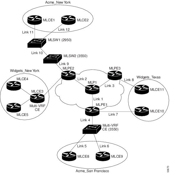
Figure 25-1 shows the topology for the network used to define the service requests in this section.
PE-CE Example
In the PE-CE example, the service provider needs to create an MPLS service for a CE (mlce1) in their customer site Acme_NY (in New York).
Multi-VRF Example
In the Multi-VRF example, the service provider needs to create an MPLS service between a CE (mlce4) in their customer site Widgets_NY (in New York) and a Multi-VRFCE (mlce3) located in their customer site Widgets_NY (in New York).
The goal is to create a single service request that defines a link between the customer site in New York and the PE (mlpe2).
PE-Only Example
In the PE-Only example, the service provider needs to create an MPLS service for a PE (mlpe2.)
Figure 25-1 Example Network Topology
Creating an MPLS VPN PE-CE Service Request
For an example of creating an MPLS VPN PE-CE service request, perform the following steps.
Step 1 ![]() Choose Operate> Service Requests > MPLS.
Choose Operate> Service Requests > MPLS.
Step 2 ![]() Choose the policy of choice, then click OK.
Choose the policy of choice, then click OK.
The MPLS Service Request Editor appears.
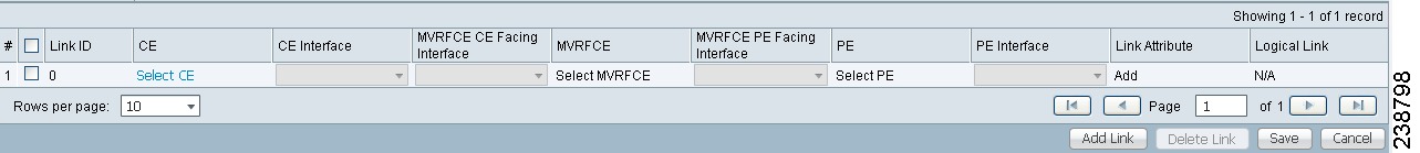
Step 3 ![]() Click Add Link.
Click Add Link.
The MPLS Service Request Editor now displays a set of fields, as shown in Figure 25-2. Notice that the Select CE field is enabled. Specifying the CE for the link is the first task required to define the link for this service.
Figure 25-2 Initial Fields Displayed to Define PE-CE Link
Step 4 ![]() CE: Click Select CE.
CE: Click Select CE.
The Select CPE Device dialog box appears, as shown in Figure 25-3.
Figure 25-3 Selecting the CE for the MPLS Link
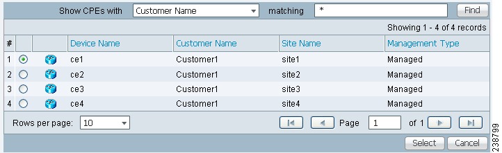
a. ![]() From the "Show CPEs with" drop-down list, you can display CEs by Customer Name, by Site, or by Device Name.
From the "Show CPEs with" drop-down list, you can display CEs by Customer Name, by Site, or by Device Name.
b. ![]() You can use the Find button to either search for a specific CE, or to refresh the display.
You can use the Find button to either search for a specific CE, or to refresh the display.
c. ![]() You can set the "Rows per page" to 5, 10, 20, 30, 40, or All.
You can set the "Rows per page" to 5, 10, 20, 30, 40, or All.
d. ![]() This dialog box displays the first page of the list of currently defined CE devices. The number of pages of information is displayed in the lower right corner of the dialog box. To go to the another page of CE devices, click the number of the page you want to go to.
This dialog box displays the first page of the list of currently defined CE devices. The number of pages of information is displayed in the lower right corner of the dialog box. To go to the another page of CE devices, click the number of the page you want to go to.
Step 5 ![]() In the Select column, choose the name of the CE for the MPLS link, then click Select.
In the Select column, choose the name of the CE for the MPLS link, then click Select.
You return to the Service Request Editor window, where the name of the selected CE is now displayed in the CE column.
Step 6 ![]() CE Interface: Choose the CE interface from the drop-down list.
CE Interface: Choose the CE interface from the drop-down list.
Note that in the PE column, the Select PE option is now enabled.
Note on Using Bundle-Ether Interfaces
The following usage notes apply to Bundle-Ether interfaces:
•![]() You can select a Bundle-Ether interface for an IOS XR device based on the interface type specified in the corresponding policy.
You can select a Bundle-Ether interface for an IOS XR device based on the interface type specified in the corresponding policy.
•![]() Bundle-Ether interfaces are only visible in the service request if one or more Bundle-Ether interfaces are pre-configured on the selected PE device. That is, port channel must be preconfigured on the device prior to creating the service request. Port channel interfaces are used for VRF termination.
Bundle-Ether interfaces are only visible in the service request if one or more Bundle-Ether interfaces are pre-configured on the selected PE device. That is, port channel must be preconfigured on the device prior to creating the service request. Port channel interfaces are used for VRF termination.
•![]() Links can be IPv4 and/or IPv6. Note the following points:
Links can be IPv4 and/or IPv6. Note the following points:
–![]() On the Cisco Carrier Routing System One (CRS-1) router, both IPv4 and IPv6 links are supported. Multicast is not supported for IPv6. See the following link for more information:
On the Cisco Carrier Routing System One (CRS-1) router, both IPv4 and IPv6 links are supported. Multicast is not supported for IPv6. See the following link for more information:
–![]() On the Cisco 12000 (also known as a Gigabit Switch Router or GSR), only IPv4 links are supported; this is a device restriction. See the following link for more information:
On the Cisco 12000 (also known as a Gigabit Switch Router or GSR), only IPv4 links are supported; this is a device restriction. See the following link for more information:
http://www.cisco.com/en/US/docs/ios/12_0s/feature/guide/lnkbndl.html
•![]() The multiple neighbor and peering with bundled physical interface feature is not supported for MVRFCE service requests.
The multiple neighbor and peering with bundled physical interface feature is not supported for MVRFCE service requests.
Step 7 ![]() PE: Click Select PE.
PE: Click Select PE.
The Select PE Device dialog box appears.
a. ![]() From the "Show PEs with" drop-down list, you can display PEs by Customer Name, by Site, or by Device Name.
From the "Show PEs with" drop-down list, you can display PEs by Customer Name, by Site, or by Device Name.
b. ![]() You can use the Find button to either search for a specific PE, or to refresh the display.
You can use the Find button to either search for a specific PE, or to refresh the display.
c. ![]() You can set the "Rows per page" to 5, 10, 20, 30, 40, or All.
You can set the "Rows per page" to 5, 10, 20, 30, 40, or All.
d. ![]() This dialog box displays the first page of the list of currently defined PE devices. The number of pages of information is displayed in the lower right corner of the dialog box.
This dialog box displays the first page of the list of currently defined PE devices. The number of pages of information is displayed in the lower right corner of the dialog box.
To go to the another page of PE devices, click the number of the page you want to go to.
Step 8 ![]() In the Select column, choose the name of the PE for the MPLS link, then click Select.
In the Select column, choose the name of the PE for the MPLS link, then click Select.
You return to the Service Request Editor window, where the name of the selected PE is now displayed in the PE column.
Step 9 ![]() PE Interface: Choose the PE interface from the drop-down list.
PE Interface: Choose the PE interface from the drop-down list.
Note that the Link Attribute Add option is now enabled.
See the section Note on Using Bundle-Ether Interfaces, for information on specifying Bundle-Ether interfaces.
Step 10 ![]() In the Link Attribute column, click Add.
In the Link Attribute column, click Add.
The MPLS Link Attribute Editor appears, showing the fields for the interface parameters, as shown in Figure 25-4.
Figure 25-4 Specifying the MPLS Link Interface Attributes
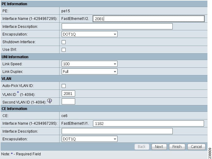
The field values displayed in this dialog box reflect the values specified in the service policy associated with this service. For details on each of the PE and CE interface fields, see Chapter 24, "Specifying PE and CE Interface Parameters".
Notes on the VLAN ID and Second VLAN ID Attributes
The VLAN ID is shared between the PE and CE, so there is one VLAN ID for both.
The Second VLAN ID is an optional attribute that provides a method to match the Q-in-Q second VLAN tag of incoming frames on the PE interface.
Usage notes:
•![]() This attribute is not available for service requests based on MVRFCE policies.
This attribute is not available for service requests based on MVRFCE policies.
•![]() This attribute does not exist at the policy level and must be set while creating the service request. There is no corresponding autopick option for the second VLAN ID, so a value must be supplied. It must be an integer from 1 to 4094.
This attribute does not exist at the policy level and must be set while creating the service request. There is no corresponding autopick option for the second VLAN ID, so a value must be supplied. It must be an integer from 1 to 4094.
•![]() This attribute is only applicable for regular PE-CE links. It is supported both when the CE is present and when it is not present. It is supported for both managed and unmanaged CE devices.
This attribute is only applicable for regular PE-CE links. It is supported both when the CE is present and when it is not present. It is supported for both managed and unmanaged CE devices.
•![]() This attribute is only applicable when the encapsulation type for the PE interface is dot1q. For all other encapsulation types, this attribute does not appear in GUI.
This attribute is only applicable when the encapsulation type for the PE interface is dot1q. For all other encapsulation types, this attribute does not appear in GUI.
•![]() This feature is available for limited platforms (only those that support Q-in-Q matching). If service requests with second VLAN ID are deployed on unsupported platforms it results in a deployment failure. In such cases, the operator can remove the second VLAN ID and redeploy the service. This would be a service-affecting operation, since the IP address is also removed and redeployed during the change.
This feature is available for limited platforms (only those that support Q-in-Q matching). If service requests with second VLAN ID are deployed on unsupported platforms it results in a deployment failure. In such cases, the operator can remove the second VLAN ID and redeploy the service. This would be a service-affecting operation, since the IP address is also removed and redeployed during the change.
•![]() A service request created with a second VLAN ID results in the following command on the IOS device:
A service request created with a second VLAN ID results in the following command on the IOS device:
encapsulation dot1q VLAN_ID second-dot1q SECOND_VLAN_ID
•![]() A service request created with a second VLAN ID results in the following command on the IOS XR device:
A service request created with a second VLAN ID results in the following command on the IOS XR device:
dot1q vlan VLAN_ID SECOND_VLAN_ID
•![]() Prime Fulfillment does not apply the second VLAN. It only supports the second VLAN matching on the PE interface.
Prime Fulfillment does not apply the second VLAN. It only supports the second VLAN matching on the PE interface.
•![]() The second VLAN ID attribute is available for use as a template variable (Second_PE_Vlan_ID).
The second VLAN ID attribute is available for use as a template variable (Second_PE_Vlan_ID).
•![]() For additional information on second VLAN ID and Q-in-Q support, see the following sections:
For additional information on second VLAN ID and Q-in-Q support, see the following sections:
–![]() Chapter 33, "CE-PE L3 MPLS VPN (Q-in-Q/Second VLAN ID, IOS)"
Chapter 33, "CE-PE L3 MPLS VPN (Q-in-Q/Second VLAN ID, IOS)"
–![]() Chapter 33, "CE-PE L3 MPLS VPN (Q-in-Q/Second VLAN ID, IOS XR)"
Chapter 33, "CE-PE L3 MPLS VPN (Q-in-Q/Second VLAN ID, IOS XR)"
–![]() Chapter 34, "Frequently Asked Questions"
Chapter 34, "Frequently Asked Questions"
Step 11 ![]() Edit any interface values that must be modified for this particular link, then click Next.
Edit any interface values that must be modified for this particular link, then click Next.
The MPLS Link Attribute Editor for the IP Address Scheme appears. The field values displayed in this dialog box reflect the values specified in the service policy associated with this service. For details on the IP address scheme fields, see Chapter 24, "Specifying the IP Address Scheme".
Step 12 ![]() Edit any IP address scheme values that must be modified for this particular link, then click Next.
Edit any IP address scheme values that must be modified for this particular link, then click Next.
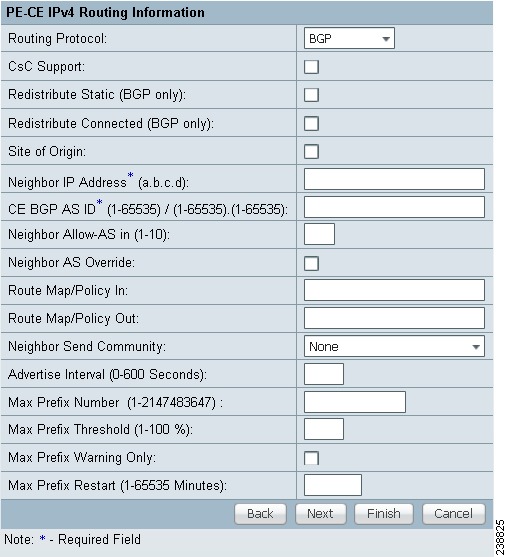
The MPLS Link Attribute Editor for Routing Information appears, as shown in Figure 25-5.
Figure 25-5 Specifying the MPLS Link Routing Protocol Attributes
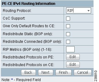
The field values displayed in this dialog box reflect the values specified in the service policy associated with this service. For details on the routing information for the PE and CE, see Chapter 24, "Specifying the Routing Protocol for a Service".
Because the service policy used for this service specified the routing protocol as editable, you can change the routing protocol for this service request as needed.
Note ![]() For the Static routing protocol, there are two additional attributes that you can add via the Link Attribute Editor. See Setting Static Routing Protocol Attributes (for IPv4 and IPv6).
For the Static routing protocol, there are two additional attributes that you can add via the Link Attribute Editor. See Setting Static Routing Protocol Attributes (for IPv4 and IPv6).
Step 13 ![]() Edit any routing protocol values that must be modified for this particular link, then click Next.
Edit any routing protocol values that must be modified for this particular link, then click Next.
Note ![]() If this interface is dual stacked (IPv4 and IPv6), you will be prompted to enter the routing information for both IPv4 and IPv6 independently.
If this interface is dual stacked (IPv4 and IPv6), you will be prompted to enter the routing information for both IPv4 and IPv6 independently.
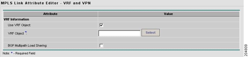
The MPLS Link Attribute Editor for the VRF and VPN attributes appears. The field values displayed in this dialog box reflect the values specified in the service policy associated with this service. For details on the VRF and VPN information, see Chapter 24, "Defining VRF and VPN Information".
Note ![]() If you want to set the VRF and VPN attributes via a previously defined VRF object, check the Use VRF Object check box. For more information on this feature, see Chapter 22, "Independent VRF Management." That chapter describes how to use independent VRF objects in MPLS VPN service policies and service requests.
If you want to set the VRF and VPN attributes via a previously defined VRF object, check the Use VRF Object check box. For more information on this feature, see Chapter 22, "Independent VRF Management." That chapter describes how to use independent VRF objects in MPLS VPN service policies and service requests.
Step 14 ![]() If multicast is enabled, choose the PIM (Protocol Independent Multicast) Mode:
If multicast is enabled, choose the PIM (Protocol Independent Multicast) Mode:
•![]() SPARSE_MODE
SPARSE_MODE
•![]() SPARCE_DENSE_MODE
SPARCE_DENSE_MODE

Tip ![]() Multicast routing architecture allows the addition of IP multicast routing on existing IP networks. PIM is an independent unicast routing protocol. It can be operated in two modes: dense and sparse.
Multicast routing architecture allows the addition of IP multicast routing on existing IP networks. PIM is an independent unicast routing protocol. It can be operated in two modes: dense and sparse.
Step 15 ![]() Edit any VRF and VPN values that must be modified for this particular link.
Edit any VRF and VPN values that must be modified for this particular link.
Note ![]() Most of the attributes available in the MPLS Link Attribute Editor - VRF and VPN window are covered in the VRF and VPN Member window of the policy workflow. For information on the common attributes, see Chapter 24, "Defining VRF and VPN Information". However, there are some differences when defining the VRF and VPN attributes in service requests. See Defining VRF and VPN Attributes in an MPLS Service Request for information on defining VRF and VPN attributes during service request creation.
Most of the attributes available in the MPLS Link Attribute Editor - VRF and VPN window are covered in the VRF and VPN Member window of the policy workflow. For information on the common attributes, see Chapter 24, "Defining VRF and VPN Information". However, there are some differences when defining the VRF and VPN attributes in service requests. See Defining VRF and VPN Attributes in an MPLS Service Request for information on defining VRF and VPN attributes during service request creation.
Step 16 ![]() Click the Next button if you want to associate templates or data files to the service request.
Click the Next button if you want to associate templates or data files to the service request.
The Template Association window appears. In this window, you can associate templates and data files with a device by clicking the Add button in Template/Data File column for the device. When you click the Add button, the Add/Remove Templates window appears.
For instructions about associating templates with service requests and how to use the features in this window, see Chapter 49, "Using Templates and Data Files with Policies and Service Requests" When you have completed setting up templates and data files for the device(s), click Finish in the Template Association window to close it and return to the Service Request Editor window.
Step 17 ![]() If you did not add templates, click Finish in the MPLS Link Editor - VRF and VPN window.
If you did not add templates, click Finish in the MPLS Link Editor - VRF and VPN window.
You return to the MPLS Service Request Editor. You can define multiple links in this service request, following the steps outlined in previous steps.
Step 18 ![]() To save your work on this first link in the service request, click Save.
To save your work on this first link in the service request, click Save.
You return to the Service Requests window, where the information for the link you just defined is now displayed, as shown in Figure 25-6.
Figure 25-6 Service Request for an MPLS Link Completed
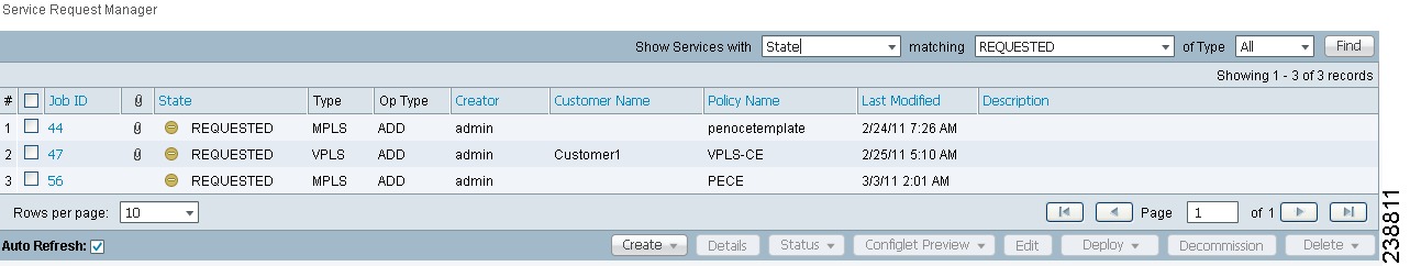
As you can see, the service request is in the Requested state. When all the links for this service have been defined, you must deploy the service, as described in Migrating PE Devices from IOS to IOS XR.
Note ![]() By default, all service requests in the Prime Fulfillment system are shown in the Service Request window. You can filter the list of service requests to be displayed by choosing different selections from the Show Services with, matching, and of type drop-down lists and clicking the Find button.
By default, all service requests in the Prime Fulfillment system are shown in the Service Request window. You can filter the list of service requests to be displayed by choosing different selections from the Show Services with, matching, and of type drop-down lists and clicking the Find button.
Note ![]() If you have only ACTIVATION, L3MPLSVPN, and VPN licenses installed for Prime Fulfillment, you cannot display all service requests based on the VPN used (by choosing VPN Name in the Show Services with drop-down list, where Type is All). The workaround for this is to display the service requests based the MPLS VPN type (by choosing MPLS VPN in the of type drop-down list). This problem does not occur if all Prime Fulfillment licenses are installed.
If you have only ACTIVATION, L3MPLSVPN, and VPN licenses installed for Prime Fulfillment, you cannot display all service requests based on the VPN used (by choosing VPN Name in the Show Services with drop-down list, where Type is All). The workaround for this is to display the service requests based the MPLS VPN type (by choosing MPLS VPN in the of type drop-down list). This problem does not occur if all Prime Fulfillment licenses are installed.
Defining VRF and VPN Attributes in an MPLS Service Request
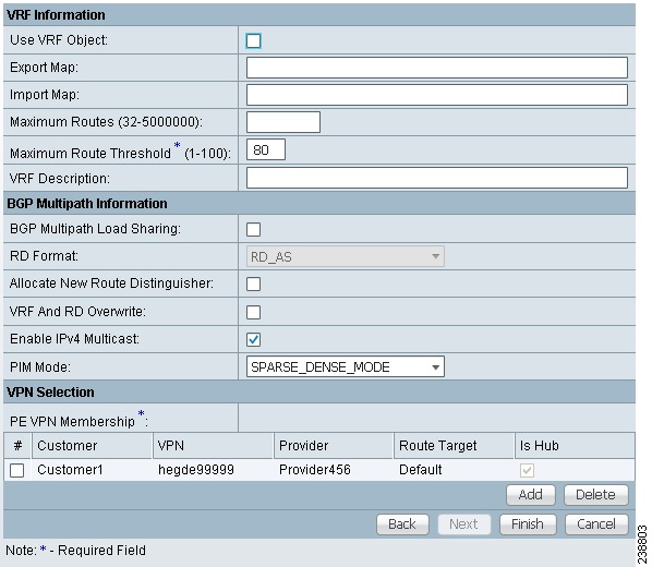
Most of the attributes available in the MPLS Link Attribute Editor - VRF and VPN window (as shown in Figure 25-7) are described in the discussion of the VRF and VPN Member window of the MPLS policy workflow. For information on defining and using these common attributes, see Chapter 24, "Defining VRF and VPN Information" in Chapter 24, "MPLS VPN Service Policies." However, there are some differences when defining the VRF and VPN attributes in service requests. There are two cases to consider, depending on whether the MPLS service request is using a VPN or if it is using an in independent VRF object. These cases are covered in separate sections below.
Figure 25-7 MPLS Link Attribute Editor - VRF and VPN window
Case 1: Using a VPN
If the service request is using a VPN, you can create an MPLS VPN link in the service request with the RD Format and RD Overwrite attributes.
Perform the following steps.
Step 1 ![]() Use VRF Object: Leave this check box unchecked.
Use VRF Object: Leave this check box unchecked.
Checking this check box causes most of the attributes to disappear from the window. This case is covered in the next section, Case 2: Using an Independent VRF Object.
Step 2 ![]() RD Format: Choose an RD format from the drop-down list. The choices are:
RD Format: Choose an RD format from the drop-down list. The choices are:
•![]() RD_AS—Route distinguisher in AS format. This is the default.
RD_AS—Route distinguisher in AS format. This is the default.
•![]() RD_IPADDR—Route distinguisher in IP address format.
RD_IPADDR—Route distinguisher in IP address format.
Usage notes:
•![]() If you select RD_IPADDR as the RD format, the GUI refreshes and displays a new attribute: RD IP Address Value, as shown in Figure 25-8.
If you select RD_IPADDR as the RD format, the GUI refreshes and displays a new attribute: RD IP Address Value, as shown in Figure 25-8.
Figure 25-8 MPLS Link Attribute Editor - VRF and VPN window
•![]() You must either manually enter the RD IP Address Value in the provided text field or else select a loopback IP address of the PE device used in the service request. To do the latter, click the Select Loopback IP button and choose the desired loopback interface in the dialogue box.
You must either manually enter the RD IP Address Value in the provided text field or else select a loopback IP address of the PE device used in the service request. To do the latter, click the Select Loopback IP button and choose the desired loopback interface in the dialogue box.
•![]() Prime Fulfillment validates the IP address entered.
Prime Fulfillment validates the IP address entered.
•![]() Only basic IPv4 addresses are allowed. No network prefixes are permitted.
Only basic IPv4 addresses are allowed. No network prefixes are permitted.
•![]() The RD is formed by appending to the IP address the VPN ID picked from the RD pool of the respective provider.
The RD is formed by appending to the IP address the VPN ID picked from the RD pool of the respective provider.
Note ![]() If you select RD_IPADDR as the RD format and use a VPN with a VPN ID greater than 65535, the service request goes to the Failed Deploy state. The reason is that if the first part of the RD value is an IP address (which is 32 bits), the second part of the RD can be only16 bits (which equates to a value from 1 to 65535).
If you select RD_IPADDR as the RD format and use a VPN with a VPN ID greater than 65535, the service request goes to the Failed Deploy state. The reason is that if the first part of the RD value is an IP address (which is 32 bits), the second part of the RD can be only16 bits (which equates to a value from 1 to 65535).
•![]() The RD options are disabled when subsequently editing the service request.
The RD options are disabled when subsequently editing the service request.
•![]() When multiple service requests with the same VPN having "manual/loopback IP" entry for RD IP Address are deployed on multiple PEs, new VRFs with unique RDs are created. This is because RD IP Address (manual/loopback IP) might differ for different devices.
When multiple service requests with the same VPN having "manual/loopback IP" entry for RD IP Address are deployed on multiple PEs, new VRFs with unique RDs are created. This is because RD IP Address (manual/loopback IP) might differ for different devices.
•![]() The following Prime Fulfillment template variables support RD Format:
The following Prime Fulfillment template variables support RD Format:
–![]() RD_FORMAT
RD_FORMAT
–![]() RD_IPADDRESS
RD_IPADDRESS
Step 3 ![]() Check the Unique Route Distinguisher: and Allocate New Route Distinguisher: check boxes based on the RD Format selection.
Check the Unique Route Distinguisher: and Allocate New Route Distinguisher: check boxes based on the RD Format selection.
Step 4 ![]() PE VPN Membership: Specify the VPN associated with this service policy.
PE VPN Membership: Specify the VPN associated with this service policy.
Usage notes:
•![]() The PE VPN Membership information includes the customer name, VPN name, service provider name, Route Targets name, Route Targets type, and whether the Route Targets type is a hub-and-spoke Route Targets or a fully meshed Route Targets.
The PE VPN Membership information includes the customer name, VPN name, service provider name, Route Targets name, Route Targets type, and whether the Route Targets type is a hub-and-spoke Route Targets or a fully meshed Route Targets.
•![]() If you choose a VPN that is already being used in a service request using the same PE, the same RD Format and RD IP Address Value is picked for the new service request and the RD Format and RD IP Address Value attributes are disabled.
If you choose a VPN that is already being used in a service request using the same PE, the same RD Format and RD IP Address Value is picked for the new service request and the RD Format and RD IP Address Value attributes are disabled.
•![]() If you choose an IPv4, IPv6, or "dual-stacked" (both IPv4 and IPv6) VPN, additional attributes (Enable IPv4 Multicast and Enable IPv6 Multicast) appear in the VRF and VPN window.
If you choose an IPv4, IPv6, or "dual-stacked" (both IPv4 and IPv6) VPN, additional attributes (Enable IPv4 Multicast and Enable IPv6 Multicast) appear in the VRF and VPN window.
•![]() For details on using the CERC Type attribute, see the section Adding Independent IPv4 and IPv6 Route Targets for MPLS Service Requests.
For details on using the CERC Type attribute, see the section Adding Independent IPv4 and IPv6 Route Targets for MPLS Service Requests.
Migrating Existing Service Requests to the New RD Format
To migrate existing service requests to be able to use the RD format, you must do the following:
•![]() Decommission the service request.
Decommission the service request.
•![]() Redeploy the service request using RD Format, or check the VRF and RD Overwrite: check box to overwrite the RD Value using the new format (ip_address:vpn_id).
Redeploy the service request using RD Format, or check the VRF and RD Overwrite: check box to overwrite the RD Value using the new format (ip_address:vpn_id).
Note ![]() Once you specify values to sub-attributes under the VRF and RD Overwrite attribute (that is, the VRF Name and RD Value attributes) and save an MPLS service request, both of these fields are disabled and are no longer editable. This behavior was introduced in because changing the default values for the VRF Name and RD Value can alter or disable currently running service requests. Therefore, if these values need to be changed on a deployed service request, the workaround is that you must decommission and purge the service request and create a new service request. In the case of a new service request that has not yet been deployed, you must force purge the service request and then create a new service with new values.
Once you specify values to sub-attributes under the VRF and RD Overwrite attribute (that is, the VRF Name and RD Value attributes) and save an MPLS service request, both of these fields are disabled and are no longer editable. This behavior was introduced in because changing the default values for the VRF Name and RD Value can alter or disable currently running service requests. Therefore, if these values need to be changed on a deployed service request, the workaround is that you must decommission and purge the service request and create a new service request. In the case of a new service request that has not yet been deployed, you must force purge the service request and then create a new service with new values.
Adding Independent IPv4 and IPv6 Route Targets for MPLS Service Requests
Prime Fulfillment supports independent IPv4 and IPv6 route targets (RTs) for Route Targets. You can configure this feature using the Route Targets Type attribute.
Usage notes:
•![]() During service request creation, you can specify the RT type of a Route Target in the PE VPN Membership section of the VRF and VPN window, as shown in Figure 25-8. It is specified in a drop-down list in the Route Targets Type column. The list choices are:
During service request creation, you can specify the RT type of a Route Target in the PE VPN Membership section of the VRF and VPN window, as shown in Figure 25-8. It is specified in a drop-down list in the Route Targets Type column. The list choices are:
–![]() IPv4. If you select IPv4, the corresponding Route Targets are applied to the ipv4 address-family CLI in the device configuration.
IPv4. If you select IPv4, the corresponding Route Targets are applied to the ipv4 address-family CLI in the device configuration.
–![]() IPv6. If you select IPv6, the corresponding Route Targets are applied to the ipv6 address-family CLI in the device configuration.
IPv6. If you select IPv6, the corresponding Route Targets are applied to the ipv6 address-family CLI in the device configuration.
–![]() IPv4 and IPv6 (dual-stacked). If you select IPv4 and IPv6, the same RTs are applied for both address families.
IPv4 and IPv6 (dual-stacked). If you select IPv4 and IPv6, the same RTs are applied for both address families.
•![]() The choices available in the Route Targets Type drop-down list depend on the IP addressing scheme selected for the service request. This is determined by the IP Number Scheme attribute in the IP Addressing Scheme window of the MPLS Link Editor workflow.
The choices available in the Route Targets Type drop-down list depend on the IP addressing scheme selected for the service request. This is determined by the IP Number Scheme attribute in the IP Addressing Scheme window of the MPLS Link Editor workflow.
•![]() If you select IPV4 and IPV6 address family, the Route Targets type should be one of the following:
If you select IPV4 and IPV6 address family, the Route Targets type should be one of the following:
–![]() Single Route Target: IPV4 and IPV6
Single Route Target: IPV4 and IPV6
–![]() Two (or more) individual Route Targets: At least one of type IPv4 and the other(s) of type IPv6
Two (or more) individual Route Targets: At least one of type IPv4 and the other(s) of type IPv6
If you do not do this, Prime Fulfillment generates an error.
•![]() If an existing service request is deployed only for IPv4 and you later modify the service request as dual-stacked (IPv4 and IPv6), Prime Fulfillment changes the tagging for the Route Targets added based on the address family. This also applies to a case in which the service request is modified from IPv6 to dual-stacked (IPv4 and IPv6).
If an existing service request is deployed only for IPv4 and you later modify the service request as dual-stacked (IPv4 and IPv6), Prime Fulfillment changes the tagging for the Route Targets added based on the address family. This also applies to a case in which the service request is modified from IPv6 to dual-stacked (IPv4 and IPv6).
•![]() When modifying a service request, if the Route Targets type is changed, you can add or remove Route Targets/VPNs also.
When modifying a service request, if the Route Targets type is changed, you can add or remove Route Targets/VPNs also.
•![]() If VPN association is set up at the policy level and specified as non-editable, then while creating a service request using this policy, the tagging of the Route Targets types is decided based on the address family that was chosen in the policy.
If VPN association is set up at the policy level and specified as non-editable, then while creating a service request using this policy, the tagging of the Route Targets types is decided based on the address family that was chosen in the policy.
•![]() If an existing dual-stacked (IPv4 and IPv6) service request is modified to the IPv4 or IPv6 address family, Prime Fulfillment automatically changes the Route Targets tagging to the selected address family.
If an existing dual-stacked (IPv4 and IPv6) service request is modified to the IPv4 or IPv6 address family, Prime Fulfillment automatically changes the Route Targets tagging to the selected address family.
•![]() Prime Fulfillment checks for other service requests on the same PE that are using the same VPN, to make sure that RTs being used by other service requests are not modified or removed.
Prime Fulfillment checks for other service requests on the same PE that are using the same VPN, to make sure that RTs being used by other service requests are not modified or removed.
•![]() The independent RTs for IPv4 and IPv6 feature is supported with the VRF and RD Overwrite option.
The independent RTs for IPv4 and IPv6 feature is supported with the VRF and RD Overwrite option.
•![]() The independent RTs for IPv4 and IPv6 feature is not supported for MVRFCE service requests.
The independent RTs for IPv4 and IPv6 feature is not supported for MVRFCE service requests.
•![]() The independent RTs for IPv4 and IPv6 feature is not supported for independent VRF service requests and MPLS service requests using an independent VRF.
The independent RTs for IPv4 and IPv6 feature is not supported for independent VRF service requests and MPLS service requests using an independent VRF.
•![]() This feature is controlled through the DCPL property GUI\MplsVPN\UniqueRTFeatureEnable. The default value for this property is false. To use the independent RTs for IPv4 or IPv6 feature, you must set the DCPL property to true. Controlling the feature through a DCPL property ensures that other customers' flows are not affected (that is, those who do not want to use this feature). Customers who desire to use this feature can enable it through the DCPL property.
This feature is controlled through the DCPL property GUI\MplsVPN\UniqueRTFeatureEnable. The default value for this property is false. To use the independent RTs for IPv4 or IPv6 feature, you must set the DCPL property to true. Controlling the feature through a DCPL property ensures that other customers' flows are not affected (that is, those who do not want to use this feature). Customers who desire to use this feature can enable it through the DCPL property.
•![]() The following template variables are supported for independent RTs:
The following template variables are supported for independent RTs:
–![]() MPLSExportRouteTargets—Template variable for export RTs under IPv4 address family.
MPLSExportRouteTargets—Template variable for export RTs under IPv4 address family.
–![]() MPLSImportRouteTargets—Template variable for import RTs under IPv4 address family.
MPLSImportRouteTargets—Template variable for import RTs under IPv4 address family.
–![]() MPLSExportRouteTargets_IPV6—Template variable for export RTs under IPv6 address family.
MPLSExportRouteTargets_IPV6—Template variable for export RTs under IPv6 address family.
–![]() MPLSImportRouteTargets_IPV6—Template variable for import RTs under IPv6 address family.
MPLSImportRouteTargets_IPV6—Template variable for import RTs under IPv6 address family.
•![]() The following example shows how the template variables might be used in a template file.
The following example shows how the template variables might be used in a template file.
vrf MyVRF2
address-family ipv4 unicast
import route-target
#foreach($name in $MPLSImportRouteTargets)
$name
#end
export route-target
#foreach($name in $MPLSExportRouteTargets)
$name
#end
address-family ipv6 unicast
import route-target
#foreach($name in $MPLSImportRouteTargets_IPV6 )
$name
#end
export route-target
#foreach($name in $MPLSExportRouteTargets_IPV6 )
$name
#end
•![]() For example configlets of this feature, see Chapter 33, "PE L3 MPLS VPN (Outgoing Interface + Next Hop IP Address, Static Route Configuration, IOS XR and IOS)".
For example configlets of this feature, see Chapter 33, "PE L3 MPLS VPN (Outgoing Interface + Next Hop IP Address, Static Route Configuration, IOS XR and IOS)".
Case 2: Using an Independent VRF Object
If the service request is using an independent VRF object, you can specify the RD attributes as described in this section. For general coverage of creating VRF objects, working with VRF service requests, and using VRF objects in MPLS VPN policies and service requests, see Chapter 22, "Independent VRF Management."
Perform the following steps.
Step 1 ![]() Use VRF Object: Check the check box for this attribute.
Use VRF Object: Check the check box for this attribute.
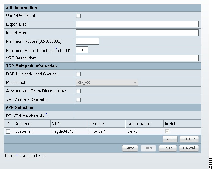
Checking this check box causes most of the attributes to disappear from the window, as shown in Figure 25-7.
Figure 25-9 MPLS Link Attribute Editor - VRF and VPN Window
Step 2 ![]() VRF Object: Click the Select button to select a previously created VRF object.
VRF Object: Click the Select button to select a previously created VRF object.
The Select Independent VRF window appears.
Step 3 ![]() Click a radio button to choose a VRF object.
Click a radio button to choose a VRF object.
Step 4 ![]() Unique RD: Check this check box to assign a unique RD and to ensure a unique RD allocation for each VRF on all PEs of the VPN.
Unique RD: Check this check box to assign a unique RD and to ensure a unique RD allocation for each VRF on all PEs of the VPN.
Note ![]() For more information on the unique RD feature in Prime Fulfillment, see Chapter 21, "Enabling a Unique Route Distinguisher for a VPN".
For more information on the unique RD feature in Prime Fulfillment, see Chapter 21, "Enabling a Unique Route Distinguisher for a VPN".
Step 5 ![]() Click Select to confirm the VRF object selection.
Click Select to confirm the VRF object selection.
The VRF and VPN window reappears showing the selected VRF object in the VRF Object field.
Usage notes:
•![]() If you select a VRF object with RD in IP address format (RD_IPADDR) and with Autopick RD enabled, then the RD Value while selecting the VRF shows up in the form IP:vpn_id. And if a manual RD is entered, it would be in the form ip_address:vpn_id, where ip_address is an IPv4 address and vpn_id is a 4-byte integer value.
If you select a VRF object with RD in IP address format (RD_IPADDR) and with Autopick RD enabled, then the RD Value while selecting the VRF shows up in the form IP:vpn_id. And if a manual RD is entered, it would be in the form ip_address:vpn_id, where ip_address is an IPv4 address and vpn_id is a 4-byte integer value.
•![]() If during the creation of the independent VRF object you selected RD_IPADDR as the RD format and enabled Autopick RD, either you can manually enter the RD IP Address Value in the text field provided or you can click the Select Loopback IP button to choose a loopback IP address of the PE device used in the service request.
If during the creation of the independent VRF object you selected RD_IPADDR as the RD format and enabled Autopick RD, either you can manually enter the RD IP Address Value in the text field provided or you can click the Select Loopback IP button to choose a loopback IP address of the PE device used in the service request.
•![]() Prime Fulfillment validates the IP address entered. Only basic IPv4 addresses are allowed. No network prefixes are permitted.
Prime Fulfillment validates the IP address entered. Only basic IPv4 addresses are allowed. No network prefixes are permitted.
•![]() The RD is formed by appending to the IP address the VPN ID picked from the RD pool of the respective provider.
The RD is formed by appending to the IP address the VPN ID picked from the RD pool of the respective provider.
•![]() After the VRF service request is deployed with the RD using the IP address entered, the RD IP Address Value field is disabled and cannot be edited.
After the VRF service request is deployed with the RD using the IP address entered, the RD IP Address Value field is disabled and cannot be edited.
•![]() If you choose a VRF which is already used in a service request using the same PE, the same RD IP Address Value is picked for the existing service request. The RD IP Address Value options are disabled.
If you choose a VRF which is already used in a service request using the same PE, the same RD IP Address Value is picked for the existing service request. The RD IP Address Value options are disabled.
•![]() If you want to change the RD Format to a new format in the case of a VRF object that is already deployed on a device, it is only possible under the following conditions:
If you want to change the RD Format to a new format in the case of a VRF object that is already deployed on a device, it is only possible under the following conditions:
–![]() All related MPLS service requests are decommissioned and purged.
All related MPLS service requests are decommissioned and purged.
–![]() The VRF service request is decommissioned, purged, and redeployed.
The VRF service request is decommissioned, purged, and redeployed.
•![]() Unique RD can be enabled for the VRF.
Unique RD can be enabled for the VRF.
Step 6 ![]() Click Next to continue setting the MPLS link attributes.
Click Next to continue setting the MPLS link attributes.
Viewing Configlets Generated by the MPLS VPN Service Request
To view configlets generated on the PE and CE device by the MPLS VPN service request, perform the following steps.
Step 1 ![]() To view the PE and CE configlets for a service request that has been successfully deployed, from the Service Request window, choose the service request you want to see, then click Details.
To view the PE and CE configlets for a service request that has been successfully deployed, from the Service Request window, choose the service request you want to see, then click Details.
The Service Request Details window appears for the associated job number.
Step 2 ![]() From Service Request Details window, click Configlets.
From Service Request Details window, click Configlets.
The Service Request Configlets window appears.
Step 3 ![]() Choose the IP address for the desired configlet, then click View Configlet.
Choose the IP address for the desired configlet, then click View Configlet.
For additional information about viewing device configlets for a deployed service request, see Chapter 47, "Viewing Service Request Configlets". For sample configlets, see Chapter 33, "Sample Configlets"
Setting Static Routing Protocol Attributes (for IPv4 and IPv6)
For the static routing protocol, in addition to the attributes that you can specify in the service policy, there are additional attributes that you can add via the Link Attribute Editor.
•![]() Advertised Routes for CE: allows you to add a list of IP addresses, static routes to put on the PE, that describes all the address space in the CE's site.
Advertised Routes for CE: allows you to add a list of IP addresses, static routes to put on the PE, that describes all the address space in the CE's site.
•![]() Routes to Reach other Sites: allows you to add a list of IP addresses, static routes to put on the CE, that describes all the address space throughout the VPN.
Routes to Reach other Sites: allows you to add a list of IP addresses, static routes to put on the CE, that describes all the address space throughout the VPN.
IPv4 Routing Information
For configuring IPv4 routing information, perform the following steps.
Step 1 ![]() When you perform Step 12 in the section Creating an MPLS VPN PE-CE Service Request for static routing protocols, the MPLS Link Attribute Editor for Routing Information appears (Figure 25-10).
When you perform Step 12 in the section Creating an MPLS VPN PE-CE Service Request for static routing protocols, the MPLS Link Attribute Editor for Routing Information appears (Figure 25-10).
Figure 25-10 Static Routing Protocol (IPv4)
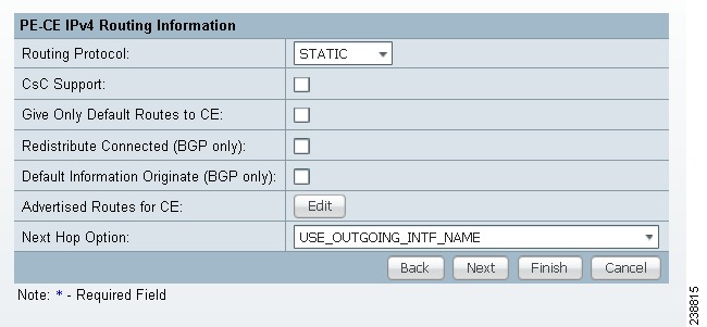
You can edit Advertised Routes for CE: and Routes to Reach other Sites: for this service request.
Step 2 ![]() To edit Advertised Routes for CE:, click Edit.
To edit Advertised Routes for CE:, click Edit.
The Advertised Routes window appears.
Step 3 ![]() Click Add to add IP addresses.
Click Add to add IP addresses.
The Advertised Routes window appears again.
Step 4 ![]() Enter an IP address and a metric.
Enter an IP address and a metric.
Step 5 ![]() Click Add to add another IP address or click OK.
Click Add to add another IP address or click OK.
Step 6 ![]() To edit Routes to Reach Other Sites:, click Edit.
To edit Routes to Reach Other Sites:, click Edit.
The Routes to reach other sites window appears.
Step 7 ![]() Click Add to add IP addresses.
Click Add to add IP addresses.
The Routes to reach other sites window appears again.
Step 8 ![]() Enter an IP address and a metric.
Enter an IP address and a metric.
Step 9 ![]() Click Add to add another IP address or click OK.
Click Add to add another IP address or click OK.
Step 10 ![]() Choose a Next Hop Option:
Choose a Next Hop Option:
•![]() USE_OUT_GOING_INTF_NAME
USE_OUT_GOING_INTF_NAME
•![]() USE_NEXT_HOP_IPADDR
USE_NEXT_HOP_IPADDR
•![]() OUTGOING_INTF_NAME+NEXT_HOP_IPADDR
OUTGOING_INTF_NAME+NEXT_HOP_IPADDR
For additional information on this choice, see Outgoing Interface Name + Next Hop IP Address Support for Static Route Configuration.
Step 11 ![]() Enter an IP address (in IPv4 format) in the Next Hop IP Address: field, if applicable.
Enter an IP address (in IPv4 format) in the Next Hop IP Address: field, if applicable.
IPv6 Routing Information
For configuring IPv6 routing information, perform the following steps.
Step 1 ![]() When you perform Step 12 in the section Creating an MPLS VPN PE-CE Service Request for static routing protocols, the MPLS Link Attribute Editor for Routing Information appears, as shown in Figure 25-11.
When you perform Step 12 in the section Creating an MPLS VPN PE-CE Service Request for static routing protocols, the MPLS Link Attribute Editor for Routing Information appears, as shown in Figure 25-11.
Figure 25-11 Static Routing Protocol (IPv6)
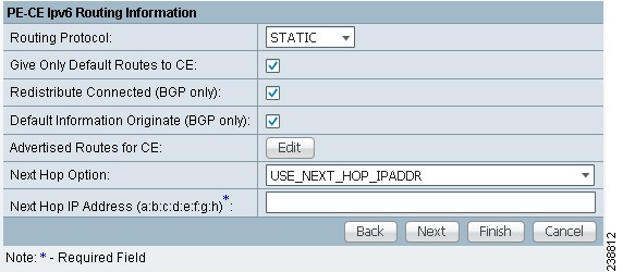
You can edit Advertised Routes for CE: for this service request.
Step 2 ![]() To edit Advertised Routes for CE:, click EDIT.
To edit Advertised Routes for CE:, click EDIT.
The Advertised Routes window appears.
Step 3 ![]() Click Add to add IP addresses.
Click Add to add IP addresses.
The Advertised Routes window appears again.
Step 4 ![]() Enter an IP address and a metric.
Enter an IP address and a metric.
Step 5 ![]() Click Add to add another IP address or click OK.
Click Add to add another IP address or click OK.
Step 6 ![]() Click Add to add IP addresses.
Click Add to add IP addresses.
Step 7 ![]() Click Add to add another IP address or click OK.
Click Add to add another IP address or click OK.
Step 8 ![]() Choose a Next Hop Option:
Choose a Next Hop Option:
•![]() USE_OUT_GOING_INTF_NAME
USE_OUT_GOING_INTF_NAME
•![]() USE_NEXT_HOP_IPADDR
USE_NEXT_HOP_IPADDR
•![]() OUTGOING_INTF_NAME+NEXT_HOP_IPADDR
OUTGOING_INTF_NAME+NEXT_HOP_IPADDR
For additional information on this choice, see Outgoing Interface Name + Next Hop IP Address Support for Static Route Configuration.
Step 9 ![]() Enter an IP address (in IPv6 format) in the Next Hop IP Address: field, if applicable.
Enter an IP address (in IPv6 format) in the Next Hop IP Address: field, if applicable.
For information on formats supported formats for entering IPv6 addresses, see MPLS VPN Policies, page 23-5.
Outgoing Interface Name + Next Hop IP Address Support for Static Route Configuration
Prime Fulfillment provides the ability to specify the outgoing interface name and next hop IP address when creating MPLS service requests for STATIC routing protocol. You do this by choosing OUTGOING_INTF_NAME+NEXT_HOP_IPADDR from the drop-down list of the Next Hop Option attribute in the MPLS Link Attribute Editor - IPv4/IPv6 Routing Information window in the MPLS service creation workflow.
When you create a service request, you set the routing protocol attributes in the MPLS Link Attribute Editor - IPv4/IPv6 Routing Information window. When you set the Routing Protocol attribute to STATIC, the window displays related attributes, including the Next Hop Option.
Usage notes:
•![]() The OUTGOING_INTF_NAME+NEXT_HOP_IPADDR selection in the Next Hop Option drop-down list enables you to provide an outgoing interface name and next hop IP address. Prime Fulfillment supports this format for static route configuration in the following form:
The OUTGOING_INTF_NAME+NEXT_HOP_IPADDR selection in the Next Hop Option drop-down list enables you to provide an outgoing interface name and next hop IP address. Prime Fulfillment supports this format for static route configuration in the following form:
network_address + outgoing_interface_name + next_hop_address
Example: 69.82.224.99/32 GigabitEthernet0/0/0/0 66.174.25.0.
•![]() This format is supported for:
This format is supported for:
–![]() PE_CE and PE_NO_CE service requests
PE_CE and PE_NO_CE service requests
–![]() IPv4 and IPv6 addressing
IPv4 and IPv6 addressing
–![]() IOS and IOS XR devices
IOS and IOS XR devices
•![]() This feature is configured only on the PE device.
This feature is configured only on the PE device.
•![]() You can configure the network address by clicking the Edit button of Advertise Routes for CE attribute.
You can configure the network address by clicking the Edit button of Advertise Routes for CE attribute.
•![]() The following template variables are supported.
The following template variables are supported.
–![]() IPv4 address family:
IPv4 address family:
Advr_Routes_IP_Address—Network IPv4 address for IPv4 address family.
Advr_Routes_Metric—Metric value for IPv4 address family.
STATIC_NEXT_HOP_IP_ADDR—Next hop IPv4 IP address for IPv4 address family.
–![]() IPv6 address family:
IPv6 address family:
Advr_Routes_IPV6_Address—Network IPv6 address for IPv6 address family.
Advr_Routes_Metric_IPV6—Metric value for IPv6 address family.
STATIC_NEXT_HOP_IPV6_ADDR—Next hop IPv6 IP address for IPv6 address family.
•![]() The following example shows how the template variables might be used in a template file for an IOS device:
The following example shows how the template variables might be used in a template file for an IOS device:
ip route vrf V2:TempIOS $Advr_Routes_IP_Address 255.255.255.255 $PE_Intf_Name
$STATIC_NEXT_HOP_IP_ADDR $Advr_Routes_Metric
•![]() The following example shows how the template variables might be used in a template file for an IOS XR device:
The following example shows how the template variables might be used in a template file for an IOS XR device:
router static
vrf V21:TempIOSXR
address-family ipv4 unicast
   $Advr_Routes_IP_Address $PE_Intf_Name $STATIC_NEXT_HOP_IP_ADDR
$Advr_Routes_Metric
!
address-family ipv6 unicast
   $Advr_Routes_IPV6_Address $PE_Intf_Name $STATIC_NEXT_HOP_IPV6_ADDR
$Advr_Routes_Metric_IPV6
•![]() For example configlets of this feature, see Chapter 33, "PE L3 MPLS VPN (Outgoing Interface + Next Hop IP Address, Static Route Configuration, IOS XR and IOS)".
For example configlets of this feature, see Chapter 33, "PE L3 MPLS VPN (Outgoing Interface + Next Hop IP Address, Static Route Configuration, IOS XR and IOS)".
Creating a Multi-VRF Service Request
MPLS-VPNs provide security and privacy as traffic travels through the provider network. The CE router has no mechanism to guarantee private networks across the traditional LAN network. Traditionally to provide privacy, either a switch needed to be deployed and each client be placed in a separate VLAN or a separate CE router is needed per each client's organization or IP address grouping attaching to a PE. These solutions are costly to the customer as additional equipment is needed and requires more network management and provisioning of each client site.
Multi-VRF, introduced in Cisco IOS release 12.2(4)T, addresses these issues. Multi-VRF extends limited PE functionality to a CE router in an MPLS-VPN model. A CE router now has the ability to maintain separate VRF tables in order to extend the privacy and security of an MPLS-VPN down to a branch office rather than just at the PE router node.
CE routers use VRF interfaces to form a VLAN-like configuration on the customer side. Each VRF on the CE router is mapped to a VRF on the PE router. With Multi-VRF, the CE router can only configure VRF interfaces and support VRF routing tables. Multi-VRF extends some of the PE functionality to the CE router—there is no label exchange, there is no LDP adjacency, there is no labeled packet flow between PE and CE. The only PE-like functionality that is supported is the ability to have multiple VRFs on the CE router so that different routing decisions can be made. The packets are sent toward the PE as IP packets.
To create a Multi-VRFCE PE-CE service request, perform the following steps.
Step 1 ![]() Choose Operate > Service Requests > MPLS.
Choose Operate > Service Requests > MPLS.
Step 2 ![]() Choose the MPLS Policy and click OK.
Choose the MPLS Policy and click OK.
The MPLS Service Request Editor window appears.
Step 3 ![]() Click Add Link.
Click Add Link.
Step 4 ![]() Click Select CE.
Click Select CE.
The Select CPE Device - CE window appears.
Step 5 ![]() Choose the CPE Device (mlce4) and then click Select.
Choose the CPE Device (mlce4) and then click Select.
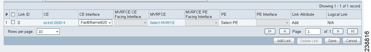
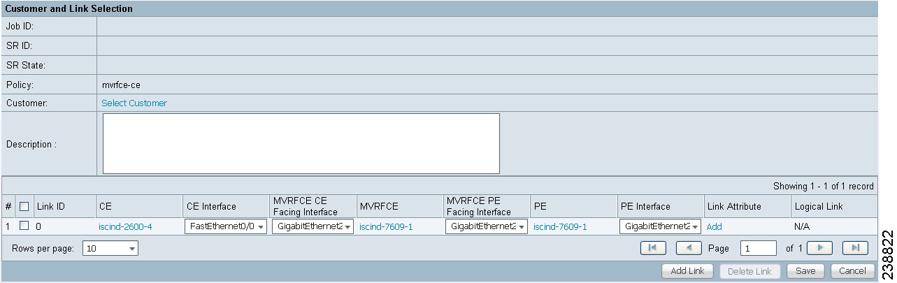
The MPLS Service Request Editor window appears, as shown in Figure 25-12.
Figure 25-12 MPLS Service Request Editor - CE Interface
Step 6 ![]() Choose the CE Interface from the drop-down box.
Choose the CE Interface from the drop-down box.
Step 7 ![]() Click Select MVRFCE.
Click Select MVRFCE.
The Select CPE Device - MVRFCE window appears.
Step 8 ![]() Choose the MVRFCE and then click Select.
Choose the MVRFCE and then click Select.
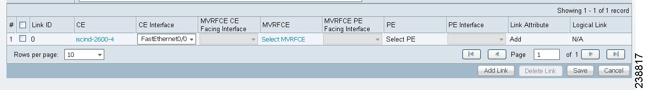
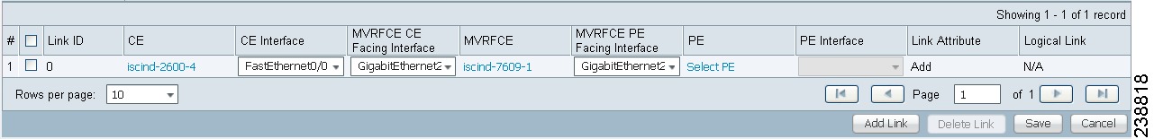
The MPLS Service Request Editor window appears, as shown in Figure 25-13.
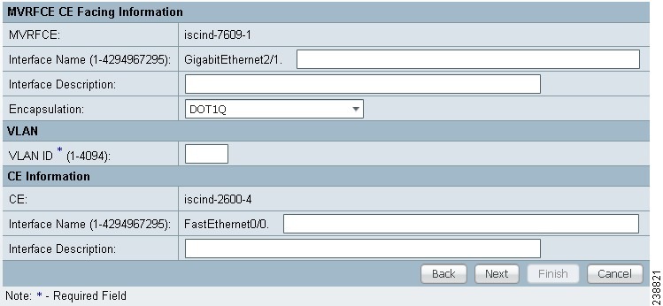
Figure 25-13 MPLS Service Request Editor - MVRFCE CE Facing Interface
Step 9 ![]() Choose the MVRFCE CE Facing Interface from the drop-down box.
Choose the MVRFCE CE Facing Interface from the drop-down box.
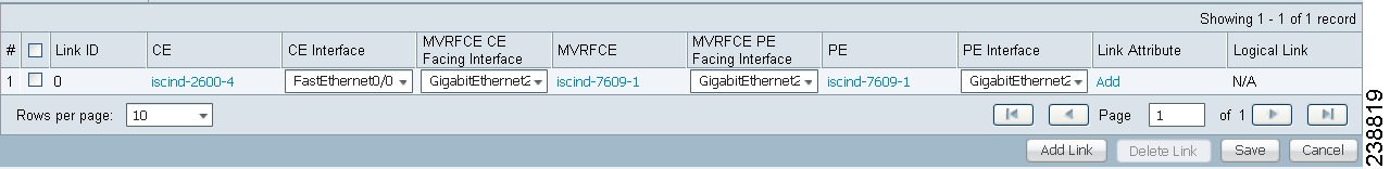
The MPLS Service Request Editor window appears, as shown in Figure 25-14.
Figure 25-14 MPLS Service Request Editor - Choose MVRFCE PE Facing Interface
Step 10 ![]() Click Select PE.
Click Select PE.
The Select PE Device window appears.
Step 11 ![]() Choose the PE and then click Select.
Choose the PE and then click Select.
The MPLS Link Attribute Editor window appears, as shown in Figure 25-15.
Figure 25-15 MPLS Link Attribute Editor - Interface
Step 12 ![]() Choose the PE Interface from the drop-down box.
Choose the PE Interface from the drop-down box.
Step 13 ![]() Click Add in the Link Attribute cell.
Click Add in the Link Attribute cell.
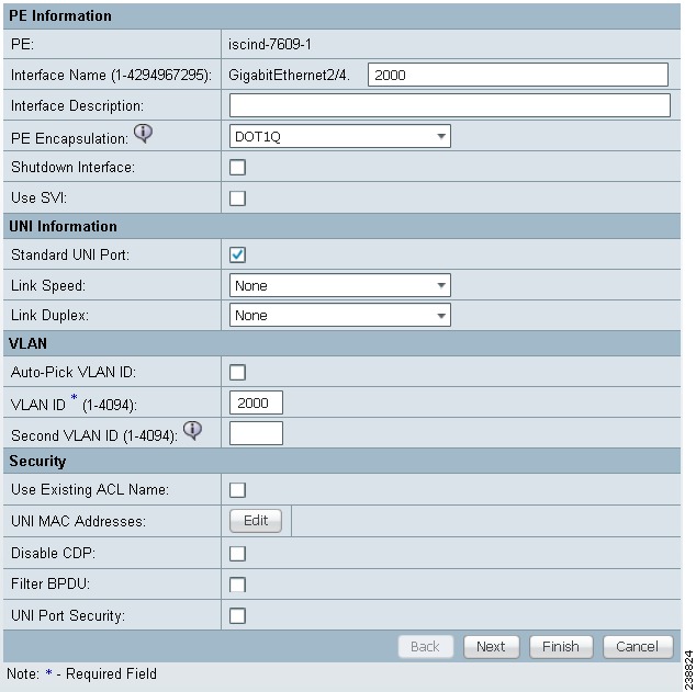
The MPLS Link Attribute Editor - Interface window appears, as shown in Figure 25-15.
Figure 25-16 MPLS Link Attribute Editor - Interface
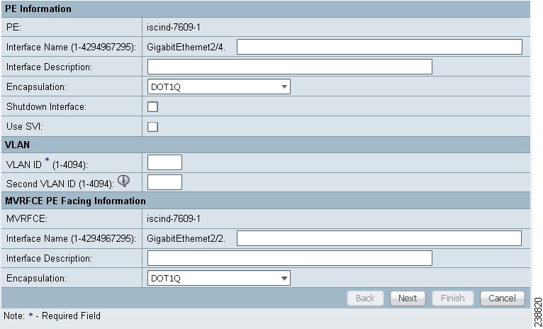
Step 14 ![]() Enter the VLAN ID for the PE. (510)
Enter the VLAN ID for the PE. (510)
Step 15 ![]() Click Next.
Click Next.
The MPLS Link Attribute Editor - Interface window appears, as shown in Figure 25-17.
Figure 25-17 MPLS Link Attribute Editor - Interface
Step 16 ![]() Enter the VLAN ID for the MVRFCE (530).
Enter the VLAN ID for the MVRFCE (530).
Step 17 ![]() Click Next.
Click Next.
The MPLS Link Attribute Editor - IP Address Scheme window appears.
Step 18 ![]() Keep the defaults, and click Next.
Keep the defaults, and click Next.
The MPLS Link Attribute Editor - IP Address Scheme window appears.
Step 19 ![]() Keep the defaults, and click Next.
Keep the defaults, and click Next.
The MPLS Link Attribute Editor - Routing Information window reappears.
Step 20 ![]() Keep the defaults and click Next.
Keep the defaults and click Next.
The MPLS Link Attribute Editor - VRF and VPN window appears.
Note ![]() For more information on setting the VRF and VPN attributes in MPLS VPN service requests, see Defining VRF and VPN Attributes in an MPLS Service Request.
For more information on setting the VRF and VPN attributes in MPLS VPN service requests, see Defining VRF and VPN Attributes in an MPLS Service Request.
Step 21 ![]() Click Add to choose a VPN.
Click Add to choose a VPN.
The Select VPN window appears.
Step 22 ![]() Choose a VPN.
Choose a VPN.
Step 23 ![]() Click Join as Hub or Join as Spoke to join the CERC.
Click Join as Hub or Join as Spoke to join the CERC.
Step 24 ![]() Click Done.
Click Done.
The MPLS Link Attribute Editor - VRF and VPN window reappears.
Step 25 ![]() Click the Next button if you want to associate templates or data files to the service request.
Click the Next button if you want to associate templates or data files to the service request.
The Template Association window appears. In this window, you can associate templates and data files with a device by clicking the Add button in Template/Data File column for the device. When you click the Add button, the Add/Remove Templates window appears. For instructions about associating templates with service requests and how to use the features in this window, see Chapter 49, "Using Templates and Data Files with Policies and Service Requests" When you have completed setting up templates and data files for the device(s), click Finish in the Template Association window to close it.
The Service Request Editor window appears.
Step 26 ![]() If you did not add templates, click Finish in the MPLS Link Editor - VRF and VPN window.
If you did not add templates, click Finish in the MPLS Link Editor - VRF and VPN window.
The MPLS Service Request Editor window appears, as shown in Figure 25-18.
Figure 25-18 MPLS Service Request Editor
Step 27 ![]() Enter the service request description and then click Save.
Enter the service request description and then click Save.
The MPLS Service Requests window appears showing that the service request is in the Requested state and ready to deploy.
Creating a PE-Only Service Request
To create a PE-only service request, perform the following steps.
Step 1 ![]() Choose Operate > Service Requests > MPLS.
Choose Operate > Service Requests > MPLS.
Step 2 ![]() Choose the policy that has CE not present, then click OK.
Choose the policy that has CE not present, then click OK.
The MPLS Service Request Editor appears.
Step 3 ![]() Click Add Link.
Click Add Link.
The MPLS Service Request Editor now displays a set of fields. Notice that the Select PE field is enabled. Specifying the PE for the link is the first task required to define the link for this service, unless a CLE switch link is needed. If a CLE switch is needed go to "Adding a CLE to a Service Request" section.
Step 4 ![]() PE: Click Select PE.
PE: Click Select PE.
The Select PE Device dialog box appears.
a. ![]() From the "Show PEs with" drop-down list, you can display PEs by Provider Name, by Region, or by Device Name.
From the "Show PEs with" drop-down list, you can display PEs by Provider Name, by Region, or by Device Name.
b. ![]() You can use the Find button to either search for a specific PE, or to refresh the display.
You can use the Find button to either search for a specific PE, or to refresh the display.
c. ![]() You can set the "Rows per page" to 5, 10, 20, 30, 40, or All.
You can set the "Rows per page" to 5, 10, 20, 30, 40, or All.
d. ![]() This dialog box displays the first page of the list of currently defined PE devices. The number of pages of information is displayed in the lower right corner of the dialog box.
This dialog box displays the first page of the list of currently defined PE devices. The number of pages of information is displayed in the lower right corner of the dialog box.
To go to the another page of PE devices, click the number of the page you want to go to.
Step 5 ![]() In the Select column, choose the name of the PE for the MPLS link, then click Select.
In the Select column, choose the name of the PE for the MPLS link, then click Select.
You return to the Service Request Editor window, where the name of the selected PE is now displayed in the PE column.
Step 6 ![]() PE Interface: Choose the PE interface from the drop-down list, as shown in Figure 25-19.
PE Interface: Choose the PE interface from the drop-down list, as shown in Figure 25-19.
Figure 25-19 PE and PE Interface Fields Defined
Note that the Link Attribute Add option is now enabled.
Step 7 ![]() In the Link Attribute column, click Add.
In the Link Attribute column, click Add.
The MPLS Link Attribute Editor appears, showing the fields for the interface parameters, as shown in Figure 25-20.
Figure 25-20 Specifying the PE-Only Link Interface Attributes
The field values displayed in this window reflect the values specified in the service policy associated with this service. For details on the PE interface fields, see Chapter 24, "Specifying PE and CE Interface Parameters".
Note ![]() For information on setting the VLAN ID and Second VLAN ID attributes, see Notes on the VLAN ID and Second VLAN ID Attributes.
For information on setting the VLAN ID and Second VLAN ID attributes, see Notes on the VLAN ID and Second VLAN ID Attributes.
Step 8 ![]() Edit any interface values that must be modified for this particular link, then click Next.
Edit any interface values that must be modified for this particular link, then click Next.
The MPLS Link Attribute Editor for the IP Address Scheme appears. The field values displayed in this dialog box reflect the values specified in the service policy associated with this service. For details on the IP address scheme fields, see Chapter 24, "Specifying the IP Address Scheme".
Step 9 ![]() Edit any IP address scheme values that must be modified for this particular link, then click Next.
Edit any IP address scheme values that must be modified for this particular link, then click Next.
The MPLS Link Attribute Editor for Routing Information appears, as shown in Figure 25-21.
Figure 25-21 Specifying the PE-Only Routing Protocol Attributes (IPv4)
The field values displayed in this dialog box reflect the values specified in the service policy associated with this service. For details on the routing information for the PE, see Chapter 24, "Specifying the Routing Protocol for a Service".
Because the service policy used for this service specified the routing protocol as editable, you can change the routing protocol for this service request as needed.
Step 10 ![]() If you check Site of Origin, the screen updates to include the required step of selecting a value:
If you check Site of Origin, the screen updates to include the required step of selecting a value:
a. ![]() Click Select.
Click Select.
The Site for SOO Value window appears.
b. ![]() From the available list shown, check the check box associated with a site and its SOO value, then click Select.
From the available list shown, check the check box associated with a site and its SOO value, then click Select.
Usage notes:
•![]() The Site of Origin attribute is for IOS devices only. It does not show up at the policy level, but only appears in MPLS Link Attribute Editor window of the service request workflow. In addition, it only shows up in the case of a PE-only service request (that is, PE with no CE present).
The Site of Origin attribute is for IOS devices only. It does not show up at the policy level, but only appears in MPLS Link Attribute Editor window of the service request workflow. In addition, it only shows up in the case of a PE-only service request (that is, PE with no CE present).
•![]() The Prime Fulfillment graphical user interface (GUI) previously supported eBGP Site of Origin for IOS devices. In this release, eBGP Site of Origin is additionally supported for IPv4 eBGP neighbors on IOS XR PE devices.
The Prime Fulfillment graphical user interface (GUI) previously supported eBGP Site of Origin for IOS devices. In this release, eBGP Site of Origin is additionally supported for IPv4 eBGP neighbors on IOS XR PE devices.
•![]() There are two use cases to mention:
There are two use cases to mention:
1. ![]() If Site of Origin is enabled for a customer and the same customer is used to create a VPN used in a service request, the Site of Origin option is visible in the MPLS Link Attribute Editor window (when BGP is selected for the routing protocol). In the case of service request for a PE with no CE, when Site of Origin is enabled, the Route Map/Policy In field is disabled and cleared.
If Site of Origin is enabled for a customer and the same customer is used to create a VPN used in a service request, the Site of Origin option is visible in the MPLS Link Attribute Editor window (when BGP is selected for the routing protocol). In the case of service request for a PE with no CE, when Site of Origin is enabled, the Route Map/Policy In field is disabled and cleared.
2. ![]() If a customer is enabled for Site of Origin and the CE device uses the same customer and is used in a service request for a PE with a CE, then the Site of Origin field is not visible at the service request level. By default it takes the Site of Origin value into consideration and deploys the Site of Origin configuration to the device. As in the previous case, the Route Map/Policy In field is disabled and cleared.
If a customer is enabled for Site of Origin and the CE device uses the same customer and is used in a service request for a PE with a CE, then the Site of Origin field is not visible at the service request level. By default it takes the Site of Origin value into consideration and deploys the Site of Origin configuration to the device. As in the previous case, the Route Map/Policy In field is disabled and cleared.
Step 11 ![]() Edit any routing protocol values that must be modified for this particular link.
Edit any routing protocol values that must be modified for this particular link.
Note ![]() If this interface is dual stacked (IPv4 and IPv6), you will be prompted to enter the routing information for both IPv4 and IPv6 independently. When specifying IPv6 routing protocol information, the MPLS Link Attribute Editor for Routing Information may show a slightly different set of options. For information on formats supported for entering IPv6 addresses, see Chapter 23, "MPLS VPN Policies".
If this interface is dual stacked (IPv4 and IPv6), you will be prompted to enter the routing information for both IPv4 and IPv6 independently. When specifying IPv6 routing protocol information, the MPLS Link Attribute Editor for Routing Information may show a slightly different set of options. For information on formats supported for entering IPv6 addresses, see Chapter 23, "MPLS VPN Policies".
Step 12 ![]() Click Next.
Click Next.
The MPLS Link Attribute Editor for the VRF and VPN attributes appears. The field values displayed in this dialog box reflect the values specified in the service policy associated with this service. For details on the VRF and VPN information, see Chapter 24, "Defining VRF and VPN Information".
Note ![]() If you want to set the VRF and VPN attributes via a previously defined VRF object, check the Use VRF Object check box. For more information on this feature, see Chapter 22, "Independent VRF Management." That chapter describes how to use independent VRF objects in MPLS VPN service policies and service requests.
If you want to set the VRF and VPN attributes via a previously defined VRF object, check the Use VRF Object check box. For more information on this feature, see Chapter 22, "Independent VRF Management." That chapter describes how to use independent VRF objects in MPLS VPN service policies and service requests.
Note ![]() For more information on setting the VRF and VPN attributes in MPLS VPN service requests, see Defining VRF and VPN Attributes in an MPLS Service Request.
For more information on setting the VRF and VPN attributes in MPLS VPN service requests, see Defining VRF and VPN Attributes in an MPLS Service Request.
Step 13 ![]() Edit any VRF and VPN values that must be modified for this particular link.
Edit any VRF and VPN values that must be modified for this particular link.
Step 14 ![]() Click the Next button, if you want to associate templates or data files to the service request.
Click the Next button, if you want to associate templates or data files to the service request.
The Template Association window appears. In this window, you can associate templates and data files with a device by clicking the Add button in Template/Data File column for the device. When you click the Add button, the Add/Remove Templates window appears. For instructions about associating templates with service requests and how to use the features in this window, see Chapter 49, "Using Templates and Data Files with Policies and Service Requests" When you have completed setting up templates and data files for the device(s), click Finish in the Template Association window.
The Service Request Editor window appears. You can define multiple links in this service request by following the steps outlined in the previous steps.
Step 15 ![]() If you did not add templates, click Finish in the MPLS Link Editor - VRF and VPN window.
If you did not add templates, click Finish in the MPLS Link Editor - VRF and VPN window.
The Service Request Editor window appears.
Step 16 ![]() To save your work on this first link in the service request, click Save.
To save your work on this first link in the service request, click Save.
You return to the Service Requests dialog box, where the information for the link you just defined is now displayed.
You can add additional links to this service request by choosing Add Link and specifying the attributes of the next link in the service. As you can see, the service request is in the Requested state. When all the links for this service have been defined, you must deploy the service, as described in Migrating PE Devices from IOS to IOS XR.
Adding a CLE to a Service Request
To add a CLE device to the service request described in Creating a PE-Only Service Request, perform the following steps.
Step 1 ![]() Follow Step 1 through Step 5 of Creating a PE-Only Service Request.
Follow Step 1 through Step 5 of Creating a PE-Only Service Request.
Step 2 ![]() Click Select CLE. The Select PE Device dialog box appears.
Click Select CLE. The Select PE Device dialog box appears.
a. ![]() From the "Show PEs with" drop-down list, you can display PEs by Provider Name, by Region, or by Device Name.
From the "Show PEs with" drop-down list, you can display PEs by Provider Name, by Region, or by Device Name.
b. ![]() You can use the Find button to either search for a specific PE, or to refresh the display.
You can use the Find button to either search for a specific PE, or to refresh the display.
c. ![]() You can set the "Rows per page" to 5, 10, 20, 30, 40, or All.
You can set the "Rows per page" to 5, 10, 20, 30, 40, or All.
d. ![]() This dialog box displays the first page of the list of currently defined PE devices. The number of pages of information is displayed in the lower right corner of the dialog box.
This dialog box displays the first page of the list of currently defined PE devices. The number of pages of information is displayed in the lower right corner of the dialog box.
To go to the another page of PE devices, click the number of the page you want to go to.
Step 3 ![]() In the Select column, choose the name of the CLE for the MPLS link, then click Select.
In the Select column, choose the name of the CLE for the MPLS link, then click Select.
You return to the Service Request Editor window, where the name of the selected CLE is now displayed in the CLE column.
Step 4 ![]() CLE Interface: Choose the CLE interface from the drop-down list.
CLE Interface: Choose the CLE interface from the drop-down list.
Step 5 ![]() Continue following Step 4 through Step 16 of "Creating a PE-Only Service Request" section.
Continue following Step 4 through Step 16 of "Creating a PE-Only Service Request" section.
Migrating PE Devices from IOS to IOS XR
For assistance in migrating services deployed on IOS devices to IOS XR devices, contact Cisco Advanced Services.
 Feedback