- About This Book
-
- Getting Started
- Setting Up the Prime Fulfillment Services for L2VPN
- Creating a FlexUNI/EVC Ethernet Policy
- Creating a FlexUNI/EVC Ethernet Service Request
- Creating a FlexUNI/EVC ATM-Ethernet Interworking Policy
- Creating a FlexUNI/EVC ATM-Ethernet Interworking Service Request
- Creating an L2VPN Policy
- Creating an L2VPN Service Request
- Creating a VPLS Policy
- Creating a VPLS Service Request
- Deploying, Monitoring, and Auditing Service Requests
- Using Auto Discovery for L2 Services
- Sample Configlets
- Setting Up VLAN Translation
-
- Getting Started with MPLS VPN
- Setting Up the Prime Fulfillment Services
- Independent VRF Management
- IPv6 and 6VPE Support in MPLS VPN
- MPLS VPN Service Policies
- MPLS VPN Service Requests
- Provisioning Regular PE-CE Links
- Provisioning Multi-VRFCE PE-CE Links
- Provisioning Management VPN
- Provisioning Cable Services
- Provisioning Carrier Supporting Carrier
- Provisioning Multiple Devices
- Spanning Multiple Autonomous Systems
- Sample Configlets
- Troubleshooting MPLS VPNs
Cisco Prime Fulfillment User Guide 6.1
Bias-Free Language
The documentation set for this product strives to use bias-free language. For the purposes of this documentation set, bias-free is defined as language that does not imply discrimination based on age, disability, gender, racial identity, ethnic identity, sexual orientation, socioeconomic status, and intersectionality. Exceptions may be present in the documentation due to language that is hardcoded in the user interfaces of the product software, language used based on RFP documentation, or language that is used by a referenced third-party product. Learn more about how Cisco is using Inclusive Language.
- Updated:
- March 20, 2015
Chapter: Basic Tunnel Management
Basic Tunnel Management
This chapter describes the processes involved in creating primary and backup tunnels with Prime Fulfillment. To create a tunnel, certain steps must first be performed as described in previous chapters.
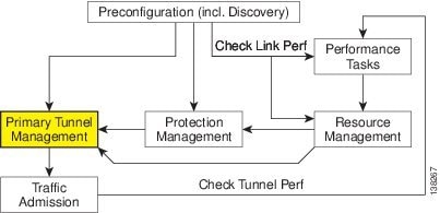
The highlighted box in Figure 38-1 shows where in Prime Fulfillment primary tunnel management occurs.
Figure 38-1 Prime Fulfillment Process Diagram - Primary Tunnel Management
This chapter includes the following sections:
Overview
Primary tunnels are characterized by carrying traffic during normal operation. They have a prioritized list of possible paths, by which traffic can be routed. At any one time, the highest priority path available will be used to route traffic. If this fails, traffic will normally be rerouted via the next available path until a higher priority path becomes available again.
Prior to setting up the tunnel, a TE policy governing the traffic must be defined. An explicit path is created to establish the route and, in the case of a primary tunnel, it is created as either a managed or an unmanaged tunnel.
The purpose of a backup tunnel is to carry Fast Re-Route (FRR) protected traffic around a failed element until the routing in the network has reconverged. It is intended to protect traffic travelling along primary tunnels. There can be many backup tunnels protecting the same traffic through the use of load balancing.
If the network fails to reconverge, the backup tunnel will remain in place.
The difference between managed and unmanaged tunnels is described in the section on Managed/Unmanaged Primary Tunnels in the Cisco Prime Fulfillment Theory of Operations Guide 6.1.
The concept of bandwidth pools from which tunnels reserve bandwidth is important to understand. This is described in the section on Bandwidth Pools in the Cisco Prime Fulfillment Theory of Operations Guide 6.1.
Create TE Policy
To create a primary tunnel, each primary tunnel must be associated with a policy. A policy can be used by multiple tunnels.
For backup tunnels, this step is not necessary. In this case, proceed to Create Explicit Path.
For other TE policy management operations, see TE Policies, page 42-2.
The TE policy is a set of rules governing the TE network and defines the Class-of-Service (for example, gold, silver, bronze) for primary tunnel traffic.
Prime Fulfillment has a notion of Managed and Unmanaged policies. Managed policies have setup/hold priorities of 0/0 and can have additional routing constraints such as protection level and max delay. Tunnels with Unmanaged policies are provisioned by the system, but the system only tracks the deployment, not the operation of the tunnel. Unmanaged policies cannot have a setup/hold priority of zero.
For more information about managed and unmanaged primary tunnels, see the section on Managed/Unmanaged Primary Tunnels in the Cisco Prime Fulfillment Theory of Operations Guide 6.1.
Policies are managed under Policies in Service Design. For a more detailed explanation of the Policies GUI, see TE Policies, page 42-2.
To create a TE policy, use the following steps:
Step 1 ![]() Choose Traffic Engineering > Policy Manager.
Choose Traffic Engineering > Policy Manager.
The Policy Manager window appears.
Step 2 ![]() Click Create and select TE Policy to set up a new TE policy.
Click Create and select TE Policy to set up a new TE policy.
To edit an existing policy, select the policy that you want to modify and click Edit. The TE Policy Editor window appears.

Note ![]() A policy that is being used by a tunnel cannot be modified. However, the name and ownership of an in-use policy can be changed.
A policy that is being used by a tunnel cannot be modified. However, the name and ownership of an in-use policy can be changed.
For an explanation of the various window elements, see TE Policies, page 42-2.
Step 3 ![]() Fill in the required fields marked with an asterisk (*) and any optional fields.
Fill in the required fields marked with an asterisk (*) and any optional fields.
If you intend to use the TE policy for managed tunnels, make sure to check the Managed check box.
When setting up a policy for a managed tunnel, the Setup and Hold priorities are automatically set to zero (highest priority). In the case of a policy for an unmanaged tunnel, you can specify the desired Setup and Hold priority settings.
Step 4 ![]() Click Save.
Click Save.
Create Explicit Path
Paths are defined between source and destination routers, possibly with one or more hops in between. Paths are used for primary and backup tunnels in the explicit path option(s).
If you intend to create an explicit path for managed tunnels, the path should not contain any non-TE enabled interfaces. Paths with non-TE enabled interfaces will be filtered out by the tunnel path chooser of the tunnel editor for managed tunnels and backup tunnels (not unmanaged tunnels).
To create or edit an explicit path, use the following steps:
Step 1 ![]() Choose Traffic Engineering > Explicit Paths.
Choose Traffic Engineering > Explicit Paths.
The TE Explicit Path List window appears.
Step 2 ![]() To create an explicit path in the TE Explicit Path List, click Create.
To create an explicit path in the TE Explicit Path List, click Create.
The New TE Explicit Path window appears.
To edit an explicit path in the explicit path list, select the explicit path that you want to modify and click Edit. This opens the TE Explicit Path Editor window.
Note ![]() An explicit path that is being used by a tunnel cannot be modified. However, use Edit to view the path.
An explicit path that is being used by a tunnel cannot be modified. However, use Edit to view the path.
The New TE Explicit Path window includes the following GUI elements:
•![]() Path Name—Name of explicit path.
Path Name—Name of explicit path.
•![]() Head Router—Name of the head router.
Head Router—Name of the head router.
•![]() Path Type—Three types of explicit paths are supported:
Path Type—Three types of explicit paths are supported:
–![]() STRICT—All strict hops are defined in the path.
STRICT—All strict hops are defined in the path.
–![]() LOOSE—Any loose hops (pure loose path or a combination of loose and strict hops) are defined in the path.
LOOSE—Any loose hops (pure loose path or a combination of loose and strict hops) are defined in the path.
–![]() EXCLUDE—All exclude hops are defined in the path.
EXCLUDE—All exclude hops are defined in the path.
•![]() Links (table)—Lists the links added for the current path and includes the following information:
Links (table)—Lists the links added for the current path and includes the following information:
–![]() Device—Hostname of the TE device that the path originates from.
Device—Hostname of the TE device that the path originates from.
–![]() Outgoing Interface—Interface name of the outgoing interface from the originating device.
Outgoing Interface—Interface name of the outgoing interface from the originating device.
–![]() Outgoing IP—IP address of the outgoing interface.
Outgoing IP—IP address of the outgoing interface.
–![]() Next Hop—Hostname of the next hop device.
Next Hop—Hostname of the next hop device.
–![]() Incoming Interface—Incoming interface name on the next hop device.
Incoming Interface—Incoming interface name on the next hop device.
–![]() Incoming IP—Incoming interface IP address on the next hop device.
Incoming IP—Incoming interface IP address on the next hop device.
•![]() Provision Preference—Preference for provisioning the next-address subcommand of the ip explicit-path command. Choose between Outgoing Interface and Incoming Interface.
Provision Preference—Preference for provisioning the next-address subcommand of the ip explicit-path command. Choose between Outgoing Interface and Incoming Interface.
–![]() Outgoing Interface—Outgoing interface on the router.
Outgoing Interface—Outgoing interface on the router.
–![]() Incoming Interface—Incoming interface on the router.
Incoming Interface—Incoming interface on the router.
Note ![]() If a path is used by any tunnel, no modifications are possible. The Outgoing Interface and Incoming Interface links are not selectable and the Provision Preference line and the Add Link, Delete Link, and Save buttons disappear.
If a path is used by any tunnel, no modifications are possible. The Outgoing Interface and Incoming Interface links are not selectable and the Provision Preference line and the Add Link, Delete Link, and Save buttons disappear.
Step 3 ![]() Specify a pathname and select a head router.
Specify a pathname and select a head router.
Step 4 ![]() Select a path type:
Select a path type:
•![]() Strict: If Strict is chosen, use the current panel that lists the connected links one by one until destination is reached.
Strict: If Strict is chosen, use the current panel that lists the connected links one by one until destination is reached.
•![]() Loose: If Loose is selected, a new hop is added by entering the IP address. If Strict is selected, you are allowed to select from TE Links list only.
Loose: If Loose is selected, a new hop is added by entering the IP address. If Strict is selected, you are allowed to select from TE Links list only.
Note ![]() For IOS XR, the Loose type is only available if the head device is running IOS XR 3.4 or later.
For IOS XR, the Loose type is only available if the head device is running IOS XR 3.4 or later.
Note ![]() If Loose is chosen, a new panel that adds a loose hop definition one by one is listed. Because a combination of strict and loose hops is allowed for a loose explicit path definition, the flexibility of including strict hops is provided with a constraint of at least a loose hop presence in the path.
If Loose is chosen, a new panel that adds a loose hop definition one by one is listed. Because a combination of strict and loose hops is allowed for a loose explicit path definition, the flexibility of including strict hops is provided with a constraint of at least a loose hop presence in the path.
•![]() Exclude—Exclude allows you to specify an exclude IP address. See Step 6.
Exclude—Exclude allows you to specify an exclude IP address. See Step 6.
Step 5 ![]() If Strict was selected, click the Add Link button to add a blank line to the hop list table.
If Strict was selected, click the Add Link button to add a blank line to the hop list table.
If Loose or Exclude was selected, an Add Hop button appears, which when clicked opens a pop-up window where you specify an IP address.
Step 6 ![]() Now an interface must be selected for the head router.
Now an interface must be selected for the head router.
Depending on the path type selection, you will see one of the following windows:
A. Strict path type:
Click the Add Link button, then click Add Interface. The Select Next Hop window appears.
The next hop list contains all the possible next hops of the router, excluding the ones already included in the explicit paths (to avoid path loops).
The next hop list contains TE interfaces and at most one non-TE interface for each router (if the loopback interface is used as the MPLS TE ID of the device). For TE interfaces, the Outgoing Interface and Outgoing IP columns are populated by the application.
Note ![]() If a non-TE interface is selected, Provision Preference is set to Incoming Interface. The provision preference cannot be set manually.
If a non-TE interface is selected, Provision Preference is set to Incoming Interface. The provision preference cannot be set manually.
Select an interface and click Select. The corresponding link information is added to the new explicit path in the Links table.
In the New TE Explicit Path window, both the incoming and outgoing interface fields are populated.
B. Loose path type:
Click the Add Hop button. The Loose Hop Definition window appears.
In this window, specify an IP address for the desired loose hop and click OK. The Loose Hop Definition window closes.
The New TE Explicit Path window now displays the added loose hop.
C. Exclude path type:
Click the Add Hop button. The Exclude Hop Definition window appears.
In this window, specify an IP address for the desired exclude hop and click OK. The Exclude Hop Definition window closes.
The New TE Explicit Path window now displays the added exclude hop.
Step 7 ![]() To add another link, click either Add Link or Add Hop.
To add another link, click either Add Link or Add Hop.
Step 8 ![]() For Strict hops, a Provision Preference can optionally be selected by clicking either the Outgoing Interface or the Incoming Interface radio button.
For Strict hops, a Provision Preference can optionally be selected by clicking either the Outgoing Interface or the Incoming Interface radio button.
Note ![]() If you try to select the Provision Preference before adding a link when non-TE interfaces are present, the Add Link process overrides the Provision Preference and sets it to incoming.
If you try to select the Provision Preference before adding a link when non-TE interfaces are present, the Add Link process overrides the Provision Preference and sets it to incoming.
Step 9 ![]() Click Save to keep the created TE explicit path or click Cancel to quit without saving.
Click Save to keep the created TE explicit path or click Cancel to quit without saving.
Delete Explicit Path
Prime Fulfillment supports decommission of explicit paths when deleting/decommissioning primary/backup tunnels. This is only supported for IOS XR.
Whether an explicit path can be deleted in such situations depends on whether they are used by other global applications.
Explicit path deletion goes hand in hand with both SR tunnel deletion for primary managed/unmanaged tunnels, backup tunnels, and any non-conformant tunnels and is applicable to all path option types (STRICT, LOOSE, EXCLUDE).
An explicit path configuration will be automatically removed by Prime Fulfillment when the explicit path is no longer used by any tunnel in the system due to a change in tunnel configuration. This situation occurs when tunnels are deleted or when tunnels are rerouted in Prime Fulfillment.
When the explicit path configuration is removed from the device, the explicit path will still exist in the Prime Fulfillment database. Such explicit paths remaining in the database can be reused.
Explicit paths do not get deleted if you reroute or delete the tunnel(s) outside of Prime Fulfillment (through CLI on the device itself, for example). However, when a transaction reroutes, deletes, or modifies a tunnel using Prime Fulfillment so that an explicit path is no longer used by any tunnels, that explicit path configuration will automatically be removed from the device.
Primary Tunnel Operations
Prime Fulfillment allows you to perform a number of primary tunnel operations, which are described in the following sections.
Create Primary Tunnel
After a TE Policy and an explicit path have been set up, a primary tunnel can be created. There are two types of primary tunnels:
•![]() Managed Primary Tunnels
Managed Primary Tunnels
•![]() Unmanaged Primary Tunnels
Unmanaged Primary Tunnels
Below, the GUI flow is described for creating unmanaged primary tunnels. It is very similar for managed primary tunnels and the few differences that exist are described in the section Managed/Unmanaged Primary Tunnels in the Cisco Prime Fulfillment Theory of Operations Guide 6.1.
To create a managed or an unmanaged primary tunnel, use the following steps:
Step 1 ![]() Choose Traffic Engineering.
Choose Traffic Engineering.
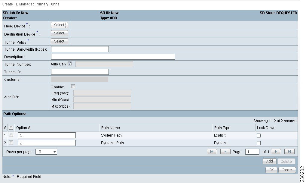
Step 2 ![]() Click Create Managed TE Tunnel. The TE Managed Primary Tunnels SR window appears as shown in Figure 38-2.
Click Create Managed TE Tunnel. The TE Managed Primary Tunnels SR window appears as shown in Figure 38-2.
or
Click Create Unmanaged TE Tunnel. The TE Unmanaged Primary Tunnels SR window appears.
Figure 38-2 Create TE Managed Primary Tunnel
The TE Managed Primary Tunnels SR window includes the following elements:
•![]() Op—SR operation on the tunnel. This can be one of the following:
Op—SR operation on the tunnel. This can be one of the following:
–![]() ADD—Indicates a newly added tunnel.
ADD—Indicates a newly added tunnel.
–![]() MODIFY—Indicates a modified existing tunnel.
MODIFY—Indicates a modified existing tunnel.
–![]() DELETE—Indicates an existing tunnel to be deleted.
DELETE—Indicates an existing tunnel to be deleted.
–![]() ADMIT—Indicates an existing tunnel to be admitted by tunnel computation.
ADMIT—Indicates an existing tunnel to be admitted by tunnel computation.
•![]() Tunnel ID—Unique tunnel identifier used within Prime Fulfillment.
Tunnel ID—Unique tunnel identifier used within Prime Fulfillment.
•![]() T#—Tunnel number on the head router.
T#—Tunnel number on the head router.
•![]() Head—Hostname of the head router.
Head—Hostname of the head router.
•![]() Dest—Hostname of the destination router.
Dest—Hostname of the destination router.
•![]() Policy—TE policy for the tunnel.
Policy—TE policy for the tunnel.
•![]() BW—The tunnel bandwidth. If the tunnel is auto-bw enabled, BW shows the higher of tunnel bandwidth and maximum automatic bandwidth.
BW—The tunnel bandwidth. If the tunnel is auto-bw enabled, BW shows the higher of tunnel bandwidth and maximum automatic bandwidth.
•![]() AutoBW—Auto Bandwidth enabled if true, otherwise false.
AutoBW—Auto Bandwidth enabled if true, otherwise false.
•![]() Deploy Status—Tunnel deployment status.
Deploy Status—Tunnel deployment status.
•![]() Verified—Indicates whether tunnel verification was successful (succeed, failed, or unknown).
Verified—Indicates whether tunnel verification was successful (succeed, failed, or unknown).
•![]() Allow Reroute—Specifies whether reroute is allowed (true or false). If reroute is not allowed, the tunnel cannot be set to movable, and hence cannot be rerouted by the operation (placement, grooming, or repair).
Allow Reroute—Specifies whether reroute is allowed (true or false). If reroute is not allowed, the tunnel cannot be set to movable, and hence cannot be rerouted by the operation (placement, grooming, or repair).
•![]() Head Region—The region to which the head router belongs.
Head Region—The region to which the head router belongs.
•![]() Tail Region—The region to which the tail router belongs.
Tail Region—The region to which the tail router belongs.
The following actions can be performed (buttons):
•![]() Display—Open a Topology Display for the network and highlight the selected primary tunnel(s). Selected tunnels are marked in color with directional arrows.
Display—Open a Topology Display for the network and highlight the selected primary tunnel(s). Selected tunnels are marked in color with directional arrows.
•![]() Details—Open the TE Tunnel Details window, which provides type, status, LSP, and other information about the tunnel.
Details—Open the TE Tunnel Details window, which provides type, status, LSP, and other information about the tunnel.
•![]() Admit—Admit selected tunnels not previously verified into the managed topology. This feature is used only for discovered tunnels that failed verification or for migrating unmanaged tunnels.
Admit—Admit selected tunnels not previously verified into the managed topology. This feature is used only for discovered tunnels that failed verification or for migrating unmanaged tunnels.
•![]() Create—Create a managed primary tunnel.
Create—Create a managed primary tunnel.
•![]() Edit—Edit a selected primary tunnel.
Edit—Edit a selected primary tunnel.
•![]() Delete—Delete selected primary tunnels.
Delete—Delete selected primary tunnels.
•![]() Import—Import tunnel data from import XML file.
Import—Import tunnel data from import XML file.
•![]() Placement Tools—These tools are available only when no change has been made to the tunnels. Apply the following functions against the current topology and tunnels:
Placement Tools—These tools are available only when no change has been made to the tunnels. Apply the following functions against the current topology and tunnels:
–![]() Groom—Analyse the managed tunnels in the network and reroute them to reduce the maximum link utilization.
Groom—Analyse the managed tunnels in the network and reroute them to reduce the maximum link utilization.
–![]() Tunnel Audit—Determine if changes to previously made SRLGs or backup tunnels have caused constraint violations in managed tunnels (this can occur when managed tunnels have FRR protection constraints).
Tunnel Audit—Determine if changes to previously made SRLGs or backup tunnels have caused constraint violations in managed tunnels (this can occur when managed tunnels have FRR protection constraints).
–![]() Tunnel Repair—Repair any managed tunnel constraint violations revealed by Placement Tools > Tunnel Audit.
Tunnel Repair—Repair any managed tunnel constraint violations revealed by Placement Tools > Tunnel Audit.
•![]() Update Tunnel ID—Update Tunnel ID(s) directly in the repository without deploying the corresponding tunnel(s).
Update Tunnel ID—Update Tunnel ID(s) directly in the repository without deploying the corresponding tunnel(s).
•![]() Proceed with Changes —For verifying changes in tunnels. When tunnels have been created, deleted, admitted, or their attributes altered, you can proceed with one of the following placement tools:
Proceed with Changes —For verifying changes in tunnels. When tunnels have been created, deleted, admitted, or their attributes altered, you can proceed with one of the following placement tools:
–![]() Tunnel Audit—Checks what constraint violations modifications to tunnels might cause.
Tunnel Audit—Checks what constraint violations modifications to tunnels might cause.
–![]() Tunnel Placement—Admit new tunnels and modify tunnels already admitted into the network.
Tunnel Placement—Admit new tunnels and modify tunnels already admitted into the network.
–![]() Tunnel Repair—Resolve inconsistencies caused by changes to bandwidth requirements or delay parameters of existing tunnels by moving as few existing tunnels as possible to accomodate the changes.
Tunnel Repair—Resolve inconsistencies caused by changes to bandwidth requirements or delay parameters of existing tunnels by moving as few existing tunnels as possible to accomodate the changes.
Note that for the unmanaged tunnels list, the last two columns in the managed tunnels list (Verified and Allow Reroute) are replaced by the Conformance column.
In the following example, an unmanaged tunnel is created.
Step 3 ![]() Click Create.
Click Create.
The Create TE Unmanaged Primary Tunnel window appears.
The Create TE Managed Primary Tunnel window and Create TE Unmanaged Primary Tunnel window have only minor differences and include the following elements:
•![]() Head Device—Head device for the tunnel.
Head Device—Head device for the tunnel.
•![]() Destination Device—Destination device for the tunnel.
Destination Device—Destination device for the tunnel.
•![]() Tunnel Policy—A set of rules established for a tunnel.
Tunnel Policy—A set of rules established for a tunnel.
•![]() Tunnel Bandwidth—Total allocated bandwidth of the tunnel.
Tunnel Bandwidth—Total allocated bandwidth of the tunnel.
•![]() Description—Descriptive text to help identify the tunnel.
Description—Descriptive text to help identify the tunnel.
•![]() Tunnel Number—Tunnel number corresponding to the tunnel interface name.
Tunnel Number—Tunnel number corresponding to the tunnel interface name.
–![]() Auto Gen—Check this box to generate the tunnel number automatically. Otherwise, enter a desired number.
Auto Gen—Check this box to generate the tunnel number automatically. Otherwise, enter a desired number.
Note ![]() If a manually entered tunnel number is too low, it could prevent deployment.
If a manually entered tunnel number is too low, it could prevent deployment.
Note ![]() MPLS-TE tunnels can potentially interfere with multicast GRE tunnels. Prime Fulfillment creates new tunnels using auto-gen and this tunnel number might already be used by an MDT GRE tunnel. As a result, Prime Fulfillment uses high tunnel numbers to avoid any complications.
MPLS-TE tunnels can potentially interfere with multicast GRE tunnels. Prime Fulfillment creates new tunnels using auto-gen and this tunnel number might already be used by an MDT GRE tunnel. As a result, Prime Fulfillment uses high tunnel numbers to avoid any complications.
•![]() Tunnel ID—Unique tunnel identifier used within Prime Fulfillment.
Tunnel ID—Unique tunnel identifier used within Prime Fulfillment.
•![]() Customer—Selected customer for the tunnel.
Customer—Selected customer for the tunnel.
•![]() Auto BW—A way to configure a tunnel for automatic bandwidth adjustment and to control the manner in which the bandwidth for a tunnel is adjusted.
Auto BW—A way to configure a tunnel for automatic bandwidth adjustment and to control the manner in which the bandwidth for a tunnel is adjusted.
–![]() Enable—Check this box to enable automatic bandwidth.
Enable—Check this box to enable automatic bandwidth.
–![]() Freq—Interval between bandwidth adjustments.
Freq—Interval between bandwidth adjustments.
–![]() Min—Minimum automatic bandwidth, in kbps, for this tunnel.
Min—Minimum automatic bandwidth, in kbps, for this tunnel.
–![]() Max—Maximum automatic bandwidth, in kbps, for this tunnel.
Max—Maximum automatic bandwidth, in kbps, for this tunnel.
Path options:
•![]() Option #—Sequential number of available explicit paths.
Option #—Sequential number of available explicit paths.
•![]() Path Name—Name of the explicit path. In case of an existing path, the name is a URL that links to the Explicit Path Viewer.
Path Name—Name of the explicit path. In case of an existing path, the name is a URL that links to the Explicit Path Viewer.
–![]() System Path—System generated explicit path. For managed tunnels, the first path has to be an explicit path. If a tunnel contains a system path, the planning function will generate an optimal path for the tunnel.
System Path—System generated explicit path. For managed tunnels, the first path has to be an explicit path. If a tunnel contains a system path, the planning function will generate an optimal path for the tunnel.
–![]() Dynamic Path—A dynamic path is provisioned by allowing the head router to find a path. The dynamic keyword is provisioned to the routers.
Dynamic Path—A dynamic path is provisioned by allowing the head router to find a path. The dynamic keyword is provisioned to the routers.
•![]() Path Type—Path option type, Explicit or Dynamic.
Path Type—Path option type, Explicit or Dynamic.
•![]() Lock Down—Disables reoptimization check on the tunnel, if checked, meaning the path cannot be changed.
Lock Down—Disables reoptimization check on the tunnel, if checked, meaning the path cannot be changed.
Step 4 ![]() To select a Head Device in the Create TE Unmanaged Primary Tunnel window, click the corresponding Select button to open the Select Device for TE Head Router window.
To select a Head Device in the Create TE Unmanaged Primary Tunnel window, click the corresponding Select button to open the Select Device for TE Head Router window.
Step 5 ![]() Select a device name and click Select.
Select a device name and click Select.
The Select Device for TE Head Router window closes and the prompt returns to the Create TE Unmanaged Primary Tunnel window.
Step 6 ![]() To select a Destination Device in the Create TE Unmanaged Primary Tunnel window, click the corresponding Select button to open the Select Device for TE Tail Router window.
To select a Destination Device in the Create TE Unmanaged Primary Tunnel window, click the corresponding Select button to open the Select Device for TE Tail Router window.
Step 7 ![]() Select a device name and click Select.
Select a device name and click Select.
The Select Device for TE Tail Router window closes and the prompt returns to the Create TE Unmanaged Primary Tunnel window.
Step 8 ![]() To select a Tunnel Policy in the Create TE Unmanaged Primary Tunnel window, click the corresponding Select button to open the Select Unmanaged TE Tunnel Policy window.
To select a Tunnel Policy in the Create TE Unmanaged Primary Tunnel window, click the corresponding Select button to open the Select Unmanaged TE Tunnel Policy window.
Note ![]() When creating a managed tunnel, make sure that one or more managed tunnel policies are available. If that is not the case, go to Policies (see Create TE Policy) and make sure to check the Managed check box.
When creating a managed tunnel, make sure that one or more managed tunnel policies are available. If that is not the case, go to Policies (see Create TE Policy) and make sure to check the Managed check box.
Step 9 ![]() Select a policy and click the Select button.
Select a policy and click the Select button.
This brings you back to the tunnel editor.
Step 10 ![]() Click Add to set up path options for the tunnel. The Select TE Explicit Path window appears.
Click Add to set up path options for the tunnel. The Select TE Explicit Path window appears.
The Path Options section provides two path types:
Explicit Path—A fixed path from a specific head to a specific destination device that includes three types of paths: Strict, Loose, and Exclude.
Dynamic Path—A dynamic path is provisioned by allowing the head router to find a path. The dynamic keyword is provisioned to the routers.
Step 11 ![]() Select the desired TE Explicit Path unless you prefer dynamic path only.
Select the desired TE Explicit Path unless you prefer dynamic path only.
If none is available, you can set one up first. To do so, see Create Explicit Path.
Step 12 ![]() Click Select.
Click Select.
The selected path appears in the Path Options section of the create window.
For explicit paths (<head_device>-<destination_device>), you can click the pathname to open the non-editable Explicit Path Viewer.
For an explanation of the various window elements, see Create Explicit Path.
Step 13 ![]() In the Create TE Unmanaged Tunnel window, click OK to accept the entered tunnel information or click Cancel to quit and return to the TE Unmanaged Primary Tunnels SR window.
In the Create TE Unmanaged Tunnel window, click OK to accept the entered tunnel information or click Cancel to quit and return to the TE Unmanaged Primary Tunnels SR window.
The TE Unmanaged Primary Tunnel SR window appears with the newly created SR with the Op field set to ADD.
Note ![]() The added tunnel can be reverted from the ADD state to its original state by selecting it and clicking Delete. The tunnel is removed from the tunnel list.
The added tunnel can be reverted from the ADD state to its original state by selecting it and clicking Delete. The tunnel is removed from the tunnel list.
Step 14 ![]() In the TE Unmanaged Primary Tunnel window, click Save & Deploy (see Note on page 11) to either deploy the new tunnel SR to the network or force deploy all tunnels, or you can create or edit more primary tunnels and then save and deploy all changes.
In the TE Unmanaged Primary Tunnel window, click Save & Deploy (see Note on page 11) to either deploy the new tunnel SR to the network or force deploy all tunnels, or you can create or edit more primary tunnels and then save and deploy all changes.
When you click Save & Deploy, Prime Fulfillment locks the TE routers effected, which will block any subsequent SRs which use that TE Router until the SRs are finished. It is safe to try and deploy other SRs in the system. If there is any conflict with the SR currently being processed, Prime Fulfillment will simply ask you to wait until it is complete.
To see the state of deployment, go to the Service Requests window at Operate > Service Request Manager or open Operate > Task Manager.
•![]() Save & Deploy—For committing tunnel changes that do not impact tunnel placement. There are two options for saving and deploying SR tunnels to the network:
Save & Deploy—For committing tunnel changes that do not impact tunnel placement. There are two options for saving and deploying SR tunnels to the network:
–![]() SR Tunnels Only—Deploy all tunnel changes that does not impact tunnel placement, or if no changes were made to the SR, use this to redeploy the SR that was in Requested or Invalid state.
SR Tunnels Only—Deploy all tunnel changes that does not impact tunnel placement, or if no changes were made to the SR, use this to redeploy the SR that was in Requested or Invalid state.
–![]() Force Deploy All Tunnels—Force deployment of all tunnels in this SR. This could be useful when previous provisioning of the SR has failed, so that it is necessary to force through the deployment of all tunnels in the SR.
Force Deploy All Tunnels—Force deployment of all tunnels in this SR. This could be useful when previous provisioning of the SR has failed, so that it is necessary to force through the deployment of all tunnels in the SR.
Note ![]() You might see Elixir Warnings during TE Tunnel deployment. The deployment will be successful and the warning messages can safely be ignored.
You might see Elixir Warnings during TE Tunnel deployment. The deployment will be successful and the warning messages can safely be ignored.
Note ![]() For managed tunnels, you cannot deploy the service request until you have used the Proceed with Changes button to perform either Tunnel Placement, Tunnel Audit, or Tunnel Repair (see Chapter 39, "Advanced Primary Tunnel Management").
For managed tunnels, you cannot deploy the service request until you have used the Proceed with Changes button to perform either Tunnel Placement, Tunnel Audit, or Tunnel Repair (see Chapter 39, "Advanced Primary Tunnel Management").
Note ![]() With the exception of TE Traffic Admission SRs, TE SRs are always deployed immediately from the specific TE SR window, not from Operate > Service Request Manager.
With the exception of TE Traffic Admission SRs, TE SRs are always deployed immediately from the specific TE SR window, not from Operate > Service Request Manager.
The Service Requests window (Operate > Service Request Manager) appears and displays the state of the deployed SR (first REQUESTED, then PENDING, then DEPLOYED, if successful).
For more information on working with service requests, see the managing service requests part elsewhere in this guide.
If the SR does not go to the Deployed state, go to the Task Logs window to see the deployment log (Operate > Task Manager > Logs) as described in SR Deployment Logs, page 56-1.
To edit the service request from the Service Request Manager window, go back to the TE Managed Primary Tunnels SR or the TE Unmanaged Primary Tunnels SR window as described in Edit Primary Tunnel.
Edit Primary Tunnel
Primary tunnel attributes can be modified in the primary tunnel editor.
There are two ways to access the primary tunnel editor:
•![]() from the managed or unmanaged primary tunnels SR window or
from the managed or unmanaged primary tunnels SR window or
•![]() from the Service Requests window.
from the Service Requests window.
Access from Primary Tunnel SR Window
To access the primary tunnel editor from the primary tunnel SR window (TE Managed Primary Tunnels SR or TE Unmanaged Primary Tunnels SR window) and edit a managed or an unmanaged primary tunnel, use the following steps:
Step 1 ![]() Choose Traffic Engineering.
Choose Traffic Engineering.
Step 2 ![]() Click Create Managed TE Tunnel. The TE Managed Primary Tunnels SR window in Figure 38-2 appears.
Click Create Managed TE Tunnel. The TE Managed Primary Tunnels SR window in Figure 38-2 appears.
or
Click Create Unmanaged TE Tunnel. The TE Unmanaged Primary Tunnels SR window appears.
Step 3 ![]() To edit a tunnel SR, select the desired SR and click Edit.
To edit a tunnel SR, select the desired SR and click Edit.
The Edit TE Managed Primary Tunnel or the Edit TE Unmanaged Primary Tunnel window appears.
The primary tunnel editor is identical to that of the create primary tunnel GUI. For an explanation of the various window elements, see Create Primary Tunnel.
Step 4 ![]() Make the desired changes and click OK to accept, or Cancel to discard the changes.
Make the desired changes and click OK to accept, or Cancel to discard the changes.
In the TE Unmanaged Primary Tunnel SR window, the Op field changes to MODIFY.
Note ![]() The modified tunnel can be reverted to its original state by selecting it and clicking Delete. The MODIFY flag in the Op column disappears.
The modified tunnel can be reverted to its original state by selecting it and clicking Delete. The MODIFY flag in the Op column disappears.
Step 5 ![]() Click Save & Deploy to either deploy the new tunnel SR to the network or force deploy all tunnels, or you can create or edit more primary tunnels and then save and deploy all changes.
Click Save & Deploy to either deploy the new tunnel SR to the network or force deploy all tunnels, or you can create or edit more primary tunnels and then save and deploy all changes.
The Service Requests window (Operate > Service Request Manager) appears and displays the state of the deployed SR.
For more information on working with service requests, see the managing service requests part elsewhere in this guide.
Access from Service Requests Window
To access the primary tunnel editor from the Service Requests window, assuming that the SR has been created, use the following steps:
Step 1 ![]() Choose Operate > Service Request Manager.
Choose Operate > Service Request Manager.
Step 2 ![]() To edit the desired tunnel SR, select the SR in question and click Edit.
To edit the desired tunnel SR, select the SR in question and click Edit.
Depending on whether a managed or an unmanaged tunnel has been selected, the TE Managed Primary Tunnel SR or the TE Unmanaged Primary Tunnel SR window appears displaying the SR selected in the Service Requests window.
Step 3 ![]() Select the tunnel SR and click Edit.
Select the tunnel SR and click Edit.
The Edit TE Unmanaged Primary Tunnel window appears.
Go to Access from Primary Tunnel SR Window and continue the process from Step 4.
Delete Primary Tunnel
To delete a managed or an unmanaged primary tunnel from the primary tunnel SR window (TE Managed Primary Tunnels SR or TE Unmanaged Primary Tunnels SR window), use the following steps:
Step 1 ![]() Choose Traffic Engineering.
Choose Traffic Engineering.
Step 2 ![]() Click Create Managed TE Tunnel. The TE Managed Primary Tunnels SR window appears.
Click Create Managed TE Tunnel. The TE Managed Primary Tunnels SR window appears.
or
Click Create Unmanaged TE Tunnel. The TE Unmanaged Primary Tunnels SR window appears.
Step 3 ![]() To delete a tunnel, select the desired tunnel(s) and click Delete.
To delete a tunnel, select the desired tunnel(s) and click Delete.
The Op field status changes to DELETE.
For an explanation of the various window elements, see Create Primary Tunnel.
Note ![]() The deleted tunnel can be reverted to its original state by selecting it and clicking Delete. The DELETE flag in the Op column disappears.
The deleted tunnel can be reverted to its original state by selecting it and clicking Delete. The DELETE flag in the Op column disappears.
Step 4 ![]() Click Save & Deploy to either deploy the new tunnel SR to the network or force deploy all tunnels, or you can create or edit more primary tunnels and then save and deploy all changes.
Click Save & Deploy to either deploy the new tunnel SR to the network or force deploy all tunnels, or you can create or edit more primary tunnels and then save and deploy all changes.
The Service Requests window (Operate > Service Request Manager) appears and displays the state of the deployed SR.
For more information on working with service requests, see the managing service requests part elsewhere in this guide.
Backup Tunnel Operations
Prime Fulfillment allows you to perform a number of backup tunnel operations, which are described in this section.
The Cisco Prime Fulfillment Theory of Operations Guide 6.1 contains a section on Connectivity Protection (CSPF) Backup Tunnels, which is one of the techniques used to provide backup protection.
Create Backup Tunnel
Backup tunnels are created in much the same way as primary tunnels. In both cases, building an explicit path is not required when an existing path already traverses the desired routers. A path can be used for any number of tunnels within its bandwidth capacity.
A precondition for creating a backup tunnel is the presence of an explicit path. To create an explicit path, see Create Explicit Path.
To create a backup tunnel, use the following steps:
Step 1 ![]() Choose Traffic Engineering > Create TE Backup Tunnel.
Choose Traffic Engineering > Create TE Backup Tunnel.
The TE Protection SR window appears.
The TE Protection SR window includes the following elements:
The columns in the tunnel list provides the following information:
•![]() Op—Current SR operation on the tunnel. This can be one of the following:
Op—Current SR operation on the tunnel. This can be one of the following:
–![]() ADD—Indicates a newly added tunnel, either calculated by the system or entered by the user.
ADD—Indicates a newly added tunnel, either calculated by the system or entered by the user.
–![]() MODIFY—Indicates a modified existing tunnel.
MODIFY—Indicates a modified existing tunnel.
–![]() DELETE—Indicates an existing tunnel to be deleted, either computed by the system or originated by the user.
DELETE—Indicates an existing tunnel to be deleted, either computed by the system or originated by the user.
•![]() Tunnel ID—Unique tunnel identifier used within Prime Fulfillment.
Tunnel ID—Unique tunnel identifier used within Prime Fulfillment.
•![]() T#—Tunnel number on the head router.
T#—Tunnel number on the head router.
•![]() Head—Hostname of the head router.
Head—Hostname of the head router.
•![]() Dest—Hostname of the destination router.
Dest—Hostname of the destination router.
•![]() BW Quota—Amount of bandwidth that this backup tunnel can protect. The router limits the LSPs that can use this backup tunnel so that the sum of the bandwidth of the LSPs does not exceed the specified amount of bandwidth. If there are multiple backup tunnels, the router will use the best-fit algorithm.
BW Quota—Amount of bandwidth that this backup tunnel can protect. The router limits the LSPs that can use this backup tunnel so that the sum of the bandwidth of the LSPs does not exceed the specified amount of bandwidth. If there are multiple backup tunnels, the router will use the best-fit algorithm.
•![]() Deploy Status—Tunnel deployment status.
Deploy Status—Tunnel deployment status.
•![]() Conformance—Indicates whether the tunnel is found to be conformant when running discovery. A tunnel is non-conformant if it has a non-zero bandwidth reservation and a zero hold or setup priority. If a tunnel is entered through TEM, it is always conformant. A connectivity protection tunnel is marked Conformant = true if it has zero tunnel bandwidth, unlimited backup bandwidth, and an 'exclude address' first path option. Otherwise, it is marked Conformant = false.
Conformance—Indicates whether the tunnel is found to be conformant when running discovery. A tunnel is non-conformant if it has a non-zero bandwidth reservation and a zero hold or setup priority. If a tunnel is entered through TEM, it is always conformant. A connectivity protection tunnel is marked Conformant = true if it has zero tunnel bandwidth, unlimited backup bandwidth, and an 'exclude address' first path option. Otherwise, it is marked Conformant = false.
•![]() Backup Type—Can be either bandwidth protected backup tunnels (BW Protected) or CSPF-routed backup tunnels (CSPF). For more information about these types of backup tunnels, see the Cisco Prime Fulfillment Theory of Operations Guide 6.1.
Backup Type—Can be either bandwidth protected backup tunnels (BW Protected) or CSPF-routed backup tunnels (CSPF). For more information about these types of backup tunnels, see the Cisco Prime Fulfillment Theory of Operations Guide 6.1.
•![]() Head Region—The region to which the head router belongs.
Head Region—The region to which the head router belongs.
•![]() Tail Region—The region to which the tail router belongs.
Tail Region—The region to which the tail router belongs.
Step 2 ![]() Click Create.
Click Create.
The Create TE Backup Tunnel window in Figure 38-3 appears.
Figure 38-3 Create TE Backup Tunnel
The Create TE Backup Tunnel window includes the following elements:
•![]() Head Device—Head device for the tunnel.
Head Device—Head device for the tunnel.
•![]() Destination Device—Destination device for the tunnel. The selection window is very similar to the Head Device selection window.
Destination Device—Destination device for the tunnel. The selection window is very similar to the Head Device selection window.
•![]() Protected Interface(s)—Interface(s) on the head router that this backup tunnel protects.
Protected Interface(s)—Interface(s) on the head router that this backup tunnel protects.
•![]() Description—Descriptive text to help identify the tunnel.
Description—Descriptive text to help identify the tunnel.
•![]() Backup Bandwidth Limit—Bandwidth protected by the backup tunnel.
Backup Bandwidth Limit—Bandwidth protected by the backup tunnel.
–![]() Any Pool BW—Bandwidth set aside for the protection of either the Sub Pool or the Global Pool.
Any Pool BW—Bandwidth set aside for the protection of either the Sub Pool or the Global Pool.
–![]() Sub Pool (BC1) BW—Bandwidth set aside for the Sub Pool.
Sub Pool (BC1) BW—Bandwidth set aside for the Sub Pool.
–![]() Global Pool (BC0) BW—Bandwidth set aside for the Global Pool.
Global Pool (BC0) BW—Bandwidth set aside for the Global Pool.
For a definition of pool types, see the Cisco Prime Fulfillment Theory of Operations Guide 6.1.
•![]() Tunnel Number—Tunnel number corresponding to the tunnel interface name.
Tunnel Number—Tunnel number corresponding to the tunnel interface name.
–![]() Auto Gen—Check this box to generate the tunnel number at provisioning time. Otherwise, enter a desired number.
Auto Gen—Check this box to generate the tunnel number at provisioning time. Otherwise, enter a desired number.
Note ![]() If a manually entered tunnel number is too low, it could prevent deployment.
If a manually entered tunnel number is too low, it could prevent deployment.
•![]() Tunnel ID—Unique tunnel identifier used within Prime Fulfillment.
Tunnel ID—Unique tunnel identifier used within Prime Fulfillment.
•![]() Tunnel Bandwidth—Total allocated bandwidth of this backup tunnel (display only).
Tunnel Bandwidth—Total allocated bandwidth of this backup tunnel (display only).
•![]() Tunnel Pool Type—Tunnel bandwidth pool type for this policy (display only). For a definition of pool types, see the Cisco Prime Fulfillment Theory of Operations Guide 6.1.
Tunnel Pool Type—Tunnel bandwidth pool type for this policy (display only). For a definition of pool types, see the Cisco Prime Fulfillment Theory of Operations Guide 6.1.
–![]() Global Pool (BC0)—Bandwidth will be reserved from Global Pool.
Global Pool (BC0)—Bandwidth will be reserved from Global Pool.
–![]() Sub Pool (BC1)—Bandwidth will be reserved from Sub Pool.
Sub Pool (BC1)—Bandwidth will be reserved from Sub Pool.
•![]() Setup Priority (0-7), Hold Priority (0-7), Affinity, Affinity Mask—All manually created backup tunnels should have setup and hold priorities of 0 and affinity value and mask of 0x0 for them to be able to protect an element.
Setup Priority (0-7), Hold Priority (0-7), Affinity, Affinity Mask—All manually created backup tunnels should have setup and hold priorities of 0 and affinity value and mask of 0x0 for them to be able to protect an element.
Path options:
•![]() Option #—Sequential number of available explicit paths.
Option #—Sequential number of available explicit paths.
•![]() Path Name—Name of the explicit path.
Path Name—Name of the explicit path.
•![]() Path Type—Explicit path type (Explicit or Dynamic)
Path Type—Explicit path type (Explicit or Dynamic)
•![]() Lock Down—Disables reoptimization check on the tunnel, if checked.
Lock Down—Disables reoptimization check on the tunnel, if checked.
Step 3 ![]() Select, at a minimum, a Head Device, a Destination Device, and a Protected Interface.
Select, at a minimum, a Head Device, a Destination Device, and a Protected Interface.
Also, specify a Backup Bandwidth Limit greater than zero. Add other tunnel information as desired.
Step 4 ![]() Click Add to add just one path.
Click Add to add just one path.
The Select TE Explicit Path window appears.
Step 5 ![]() Select an explicit path.
Select an explicit path.
It must match the head and destination of an existing path. If none is available, you first must set one up. To do so, see Create Explicit Path.
Step 6 ![]() Click Select.
Click Select.
The selected path appears in the Path Options section of the page as shown in the Select TE Explicit Path window.
For explicit paths, you can click the pathname to open the Explicit Path Viewer.
Step 7 ![]() In the Create TE Backup Tunnel window, click OK to accept the entered tunnel information or click Cancel to quit the window without saving it.
In the Create TE Backup Tunnel window, click OK to accept the entered tunnel information or click Cancel to quit the window without saving it.
In the TE Protection SR window, a new backup tunnel is added in the tunnel list with the Op field set to ADD.
Note ![]() The added tunnel can be reverted to its original state by selecting it and clicking Delete. The tunnel is removed from the tunnel list.
The added tunnel can be reverted to its original state by selecting it and clicking Delete. The tunnel is removed from the tunnel list.
Step 8 ![]() Click Save & Deploy to either deploy the new tunnel SR to the network or force deploy all tunnels, or you can create or edit more backup tunnels and then save and deploy all changes.
Click Save & Deploy to either deploy the new tunnel SR to the network or force deploy all tunnels, or you can create or edit more backup tunnels and then save and deploy all changes.
The Save & Deploy button provides two options:
–![]() SR Tunnels Only—Deploy all tunnel changes that does not impact tunnel placement, or if no changes were made to the SR, use this to redeploy the SR that was in Requested or Invalid state.
SR Tunnels Only—Deploy all tunnel changes that does not impact tunnel placement, or if no changes were made to the SR, use this to redeploy the SR that was in Requested or Invalid state.
–![]() Force Deploy All Tunnels—Force deployment of all tunnels in this SR. This could be useful when previous provisioning of the SR has failed, so that it is necessary to force through the deployment of all tunnels in the SR.
Force Deploy All Tunnels—Force deployment of all tunnels in this SR. This could be useful when previous provisioning of the SR has failed, so that it is necessary to force through the deployment of all tunnels in the SR.
When you click Save & Deploy, Prime Fulfillment locks the TE routers effected, which will block any subsequent SRs which use that TE router until the SRs are finished. It is safe to try and deploy other SRs in the system. If there is any conflict with the SR currently being processed, Prime Fulfillment will simply ask you to wait until it is complete. To see the state of deployment, go to the Service Requests window under Inventory and Connection Manager or open the Task Manager under Monitoring.
Note ![]() You might see Elixir Warnings during TE Tunnel deployment. The deployment will be successful and the warning messages can safely be ignored.
You might see Elixir Warnings during TE Tunnel deployment. The deployment will be successful and the warning messages can safely be ignored.
Note ![]() With the exception of TE Traffic Admission SRs, TE SRs are always deployed immediately from the specific TE SR window, not from the Operate > Service Request Manager page.
With the exception of TE Traffic Admission SRs, TE SRs are always deployed immediately from the specific TE SR window, not from the Operate > Service Request Manager page.
The Service Requests window (Operate > Service Request Manager) appears and displays the state of the deployed SR.
For more information on working with service requests, see the managing service requests part elsewhere in this guide.
If the SR does not go to the Deployed state, go to the Task Logs window to see the deployment log (Operate > Task Manager > Logs) as described in SR Deployment Logs, page 56-1.
Edit Backup Tunnel
Backup tunnel attributes can be modified in the backup tunnel editor.
There are two ways to access the backup tunnel editor:
•![]() from the Protection SR window or
from the Protection SR window or
•![]() from the Service Requests window.
from the Service Requests window.
From the Protection SR Window
To access the Protection SR window to edit a backup tunnel, use the following steps:
Step 1 ![]() Choose Traffic Engineering > Create TE Backup Tunnel.
Choose Traffic Engineering > Create TE Backup Tunnel.
The TE Protection SR window appears.
Step 2 ![]() To edit a tunnel SR, select the desired SR and click Edit.
To edit a tunnel SR, select the desired SR and click Edit.
The Edit TE Backup Tunnel window appears. The backup tunnel editor is identical to that of the create backup tunnel GUI. For an explanation of the various window elements, see Create Backup Tunnel.
Step 3 ![]() Make the desired changes and click OK.
Make the desired changes and click OK.
In the TE Protection window, the Op field changes to MODIFY.
Note ![]() The modified tunnel can be reverted to its original state by selecting it and clicking Delete. The MODIFY flag in the Op column disappears.
The modified tunnel can be reverted to its original state by selecting it and clicking Delete. The MODIFY flag in the Op column disappears.
Step 4 ![]() In the TE Protection SR window, click Save & Deploy to either deploy the new tunnel SR to the network or force deploy all tunnels, or you can create or edit more backup tunnels and then save and deploy all changes.
In the TE Protection SR window, click Save & Deploy to either deploy the new tunnel SR to the network or force deploy all tunnels, or you can create or edit more backup tunnels and then save and deploy all changes.
The Service Requests window (Operate > Service Request Manager) appears and displays the state of the deployed SR.
For more information on working with service requests, see the managing service requests part elsewhere in this guide.
From the Service Requests Window
To edit a backup tunnel from the Service Requests window, assuming that the SR has been created use the following steps:
Step 1 ![]() Choose Operate > Service Request Manager.
Choose Operate > Service Request Manager.
Step 2 ![]() To edit the desired tunnel SR, select the SR in question and click Edit.
To edit the desired tunnel SR, select the SR in question and click Edit.
The TE Protection SR window appears displaying the SR selected in the Service Request Manager window.
Step 3 ![]() Select the tunnel SR and click Edit.
Select the tunnel SR and click Edit.
The Edit TE Backup Tunnel window appears.
Go to Edit Backup Tunnel and continue the process from Step 3.
Delete Backup Tunnel
To delete a backup tunnel from the TE Protection SR window, use the following steps:
Step 1 ![]() Choose Traffic Engineering > Create TE Backup Tunnel.
Choose Traffic Engineering > Create TE Backup Tunnel.
The TE Protection SR window appears.
Step 2 ![]() To delete a tunnel SR, select the desired SR and click Delete.
To delete a tunnel SR, select the desired SR and click Delete.
The Op field status changes to DELETE for unmanaged tunnels.
For an explanation of the various window elements, see Create Backup Tunnel.
Note ![]() The deleted tunnel can be reverted to its original state by selecting it and clicking Delete. The DELETE flag in the Op column disappears.
The deleted tunnel can be reverted to its original state by selecting it and clicking Delete. The DELETE flag in the Op column disappears.
Click Save & Deploy to either deploy the new tunnel SR to the network or force deploy all tunnels, or you can create or edit more primary tunnels and then save and deploy all changes.
The Service Requests window (Operate > Service Request Manager) appears and displays the state of the deployed SR.
For more information on working with service requests, see the managing service requests part elsewhere in this guide.
Purging a Service Request
The Purge operation in the Service Request Manager window is designed to remove a service request from the repository without affecting the network.
The Purge button has 2 options:
•![]() Purge—The regular purge can only be used on the service request in CLOSED state. Therefore, it cannot be used on TE Resource, TE Tunnel, or TE Protection service requests because these cannot be decommissioned. These three types of service requests can only be force purged.
Purge—The regular purge can only be used on the service request in CLOSED state. Therefore, it cannot be used on TE Resource, TE Tunnel, or TE Protection service requests because these cannot be decommissioned. These three types of service requests can only be force purged.
•![]() Force Purge—During force purge, the repository checks the necessary dependency on the service request before it can be purged, so if a service request cannot be purged, there will be an error message.
Force Purge—During force purge, the repository checks the necessary dependency on the service request before it can be purged, so if a service request cannot be purged, there will be an error message.
 Feedback