- About This Book
-
- Getting Started
- Setting Up the Prime Fulfillment Services for L2VPN
- Creating a FlexUNI/EVC Ethernet Policy
- Creating a FlexUNI/EVC Ethernet Service Request
- Creating a FlexUNI/EVC ATM-Ethernet Interworking Policy
- Creating a FlexUNI/EVC ATM-Ethernet Interworking Service Request
- Creating an L2VPN Policy
- Creating an L2VPN Service Request
- Creating a VPLS Policy
- Creating a VPLS Service Request
- Deploying, Monitoring, and Auditing Service Requests
- Using Auto Discovery for L2 Services
- Sample Configlets
- Setting Up VLAN Translation
-
- Getting Started with MPLS VPN
- Setting Up the Prime Fulfillment Services
- Independent VRF Management
- IPv6 and 6VPE Support in MPLS VPN
- MPLS VPN Service Policies
- MPLS VPN Service Requests
- Provisioning Regular PE-CE Links
- Provisioning Multi-VRFCE PE-CE Links
- Provisioning Management VPN
- Provisioning Cable Services
- Provisioning Carrier Supporting Carrier
- Provisioning Multiple Devices
- Spanning Multiple Autonomous Systems
- Sample Configlets
- Troubleshooting MPLS VPNs
Cisco Prime Fulfillment User Guide 6.1
Bias-Free Language
The documentation set for this product strives to use bias-free language. For the purposes of this documentation set, bias-free is defined as language that does not imply discrimination based on age, disability, gender, racial identity, ethnic identity, sexual orientation, socioeconomic status, and intersectionality. Exceptions may be present in the documentation due to language that is hardcoded in the user interfaces of the product software, language used based on RFP documentation, or language that is used by a referenced third-party product. Learn more about how Cisco is using Inclusive Language.
- Updated:
- March 20, 2015
Chapter: MPLS VPN Service Policies
MPLS VPN Service Policies
This chapter describes how to use the Cisco Prime Fulfillment GUI to define MPLS VPN Service Policies.
Service Policy Overview
Provisioning an MPLS VPN begins with defining a service policy. A service policy can be applied to multiple PE-CE links in a single service request. A network operator defines service policies. A service operator uses a service policy to create service requests. Each service request contains a list of PE-CE links. When a service operator creates a service request, the operator sees only the policy information required to be completed. All the other necessary information is filled in by the service policy itself (as well as the Auto Discovery process).
Service Policy Editor
When you define a service policy for Prime Fulfillment, you are presented with a series of dialog boxes that allow you to specify the parameters for each major category required to complete an MPLS service request. The Service Policy editor presents three columns: Attribute, Value, and Editable:
•![]() Attribute
Attribute
The Attribute column displays the names of each parameter that you need to define for each major category (for example, IP addresses or routing protocols).
•![]() Value
Value
The Value column displays the fields and other selectable items that correspond to each parameter and option.
The type of dialog box that is invoked when you edit an attribute depends on the type of attribute. In some cases, the value is a simple string value or integer value, in which case a single text entry field appears. In other cases, the value is complex or consists of multiple values, such as an IP address. In these cases, a dialog box appears so you can specify the required values. The values you enter are validated; when invalid values are entered, you receive notification of the invalid values. In other cases, you will be presented with check boxes that will allow you to enable or disable a particular option.

Note ![]() In some cases, changing an attribute's value results in invalidating the values of related attributes. For example, changing the PE interface name can result in invalidating the PE encapsulation value. When this occurs, the service policy editor removes the invalid values and you will need to reset them appropriately.
In some cases, changing an attribute's value results in invalidating the values of related attributes. For example, changing the PE interface name can result in invalidating the PE encapsulation value. When this occurs, the service policy editor removes the invalid values and you will need to reset them appropriately.
There is a parent-child relationship between some attributes. In these cases, changing the value of a parent attribute can enable or disable the child attributes. For example, changing the value of the PE encapsulation could result in enabling or disabling the DLCI (data link connection identifier), VLAN ID, ATM circuit identifiers, and the tunnel source and destination address attributes.
•![]() Editable
Editable
The Editable column allows the network operator to indicate the attributes that are likely to change across multiple service requests. When attributes are checked as editable, only those attributes will be made available to the service operator when creating or modifying service requests with that service request policy.
When an attribute category is set to be editable, all the related and child attributes are also editable attributes.
About IP Addresses in Cisco Prime Fulfillment
Within a VPN (or extranet), all IP addresses must be unique. Customer IP addresses are not allowed to overlap with provider IP addresses. Overlap is possible only when two devices cannot see each other; that is, when they are in isolated, non-extranet VPNs.
The Prime Fulfillment MPLS VPN software assumes that it has an IP address pool to draw addresses from. The only way to guarantee that the product can use these addresses freely is if they are provider IP addresses.
Predefining a unique section (or sections) of IP address space for the PE-CE links is the only way to ensure stable security. Thus, because of the security and maintenance issues, we do not recommend using customer IP addresses on the PE-CE link.
Defining an MPLS VPN Service Policy
The remaining sections in this chapter provide an extended example of defining an MPLS service policy for a PE-CE link. This is to demonstrate the various steps involved in defining an MPLS service policy. The steps can be used as the basis for defining other types of MPLS VPN service policies. Additional types of MPLS VPN policies are described in other chapters in this guide.
To begin defining an MPLS VPN service policy for PE-CE link, perform the following steps.
Step 1 ![]() Choose the Service Design > Policies > MPLS.
Choose the Service Design > Policies > MPLS.
The MPLS Policy Editor - Policy Type dialog box appears, as shown in Figure 24-1.
Figure 24-1 Defining the MPLS Service Policy
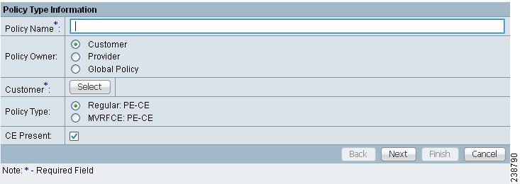
Step 2 ![]() Enter a Policy Name for the MPLS policy.
Enter a Policy Name for the MPLS policy.
Step 3 ![]() Choose the Policy Owner.
Choose the Policy Owner.
There are three types of MPLS policy ownership:
•![]() Customer ownership
Customer ownership
•![]() Provider ownership
Provider ownership
•![]() Global ownership: Any service operator can make use of this MPLS policy.
Global ownership: Any service operator can make use of this MPLS policy.
This ownership has relevance when the Prime Fulfillment Role-Based Access Control (RBAC) comes into play. For example, an MPLS policy that is customer-owned can only be seen by operators who are allowed to work on this customer-owned policy.
Similarly, operators who are allowed to work on a provider's network can view, use, and deploy a particular provider-owned policy.
Note ![]() For Cable (PE-NoCE), policy ownership should be set to Provider.
For Cable (PE-NoCE), policy ownership should be set to Provider.
Step 4 ![]() Click Select to choose the owner of the MPLS policy. (If you choose Global ownership, the Select function is not available.)
Click Select to choose the owner of the MPLS policy. (If you choose Global ownership, the Select function is not available.)
The Select Customer window or the Select Provider window appears and you can choose an owner of the policy and click Select.
Step 5 ![]() Choose the Policy Type of the MPLS policy.
Choose the Policy Type of the MPLS policy.
There are two policy types for MPLS policies:
•![]() Regular PE-CE: PE-to-CE link
Regular PE-CE: PE-to-CE link
•![]() MVRFCE PE-CE: PE to CE link using the Multi-VRF feature for the PE
MVRFCE PE-CE: PE to CE link using the Multi-VRF feature for the PE
Step 6 ![]() Check the CE Present check box if you want Prime Fulfillment to ask the service operator who uses this MPLS policy to provide a CE router and interface during service activation. The default is CE present in the service.
Check the CE Present check box if you want Prime Fulfillment to ask the service operator who uses this MPLS policy to provide a CE router and interface during service activation. The default is CE present in the service.
If you do not check the CE Present check box, Prime Fulfillment asks the service operator, during service activation, only for the PE-CLE or the PE-POP router and customer-facing interface.
Step 7 ![]() Click Next.
Click Next.
To continue with the example, see the following section, Specifying PE and CE Interface Parameters.
Specifying PE and CE Interface Parameters
The MPLS Policy Interface dialog box appears, as shown in Figure 24-2.

Tip ![]() You do not have to choose a specific interface type for the PE and CE at this point. Notice that the fields are set by default to Editable. With the interface parameters set to Editable, the service operator can specify the exact interface type and format when he or she creates the service request.
You do not have to choose a specific interface type for the PE and CE at this point. Notice that the fields are set by default to Editable. With the interface parameters set to Editable, the service operator can specify the exact interface type and format when he or she creates the service request.
If you want to specify the device interface information for this service policy when the service request is created, leave the fields as they are currently set by default, then click Next.
Figure 24-2 Specifying the PE UNI Security, and CE Interface Parameters
To specify the PE, UNI Security, and CE interface information for this MPLS policy:
PE Information
Step 1 ![]() Interface Type: From the drop-down list, choose the interface type for the PE.
Interface Type: From the drop-down list, choose the interface type for the PE.
Cisco IP Solution Center supports the following interface types (for both PEs and CEs):
•![]() Any
Any
•![]() ATM (Asynchronous Transfer Mode)
ATM (Asynchronous Transfer Mode)
•![]() BRI (Basic Rate Interface)
BRI (Basic Rate Interface)
•![]() Bundle-Ether. (For additional information, see Interface Format: Optionally, you can specify the slot number and port number for the PE interface..)
Bundle-Ether. (For additional information, see Interface Format: Optionally, you can specify the slot number and port number for the PE interface..)
•![]() Ethernet
Ethernet
•![]() Fast Ethernet
Fast Ethernet
•![]() FDDI (Fiber Distributed Data Interface)
FDDI (Fiber Distributed Data Interface)
•![]() GE-WAN (Gigabit Ethernet WAN)
GE-WAN (Gigabit Ethernet WAN)
•![]() Gigabit Ethernet
Gigabit Ethernet
•![]() HSSI (High Speed Serial Interface)
HSSI (High Speed Serial Interface)
•![]() Loopback
Loopback
•![]() MFR
MFR
•![]() MultiLink
MultiLink
•![]() PoS (Packet over Sonet)
PoS (Packet over Sonet)
•![]() Port-Channel
Port-Channel
•![]() Serial
Serial
•![]() Switch
Switch
•![]() Tunnel
Tunnel
•![]() VLAN
VLAN
Step 2 ![]() Interface Format: Optionally, you can specify the slot number and port number for the PE interface.
Interface Format: Optionally, you can specify the slot number and port number for the PE interface.
Specify the format in the standard nomenclature: slot number/port number (for example, 1/0 indicates that the interface is located at slot 1, port 0).
This is especially useful to specify here if you know that the link will always go through a particular interface's slot/port location on all or most of the network devices in the service. If this parameter is left editable, it can be changed when the service operator creates the service request.
You can also specify the Interface Format as a Channelized Interface:
•![]() slot/subSlot/port (for example, 2/3/4 indicates that the interface is located at Serial 2/3/4)
slot/subSlot/port (for example, 2/3/4 indicates that the interface is located at Serial 2/3/4)
•![]() slot/subSlot/port/T1#:channelGroup# (for example, 2/0/4/6:8 indicates that the interface is located at Serial 2/0/4/6:8)
slot/subSlot/port/T1#:channelGroup# (for example, 2/0/4/6:8 indicates that the interface is located at Serial 2/0/4/6:8)
•![]() slot/subSlot/port.STS-1Path/T1#:channelGroup# (for example, 2/0/0.1/6:8 indicates that the interface is located at Serial 2/0/0.1/6:8)
slot/subSlot/port.STS-1Path/T1#:channelGroup# (for example, 2/0/0.1/6:8 indicates that the interface is located at Serial 2/0/0.1/6:8)
Step 3 ![]() Interface Description: Optionally, you can enter a description of the PE interface.
Interface Description: Optionally, you can enter a description of the PE interface.
Step 4 ![]() Shutdown Interface: When you check this check box, the specified PE interface is configured in a shut down state.
Shutdown Interface: When you check this check box, the specified PE interface is configured in a shut down state.
Step 5 ![]() Encapsulation: Choose the encapsulation used for the specified PE interface type.
Encapsulation: Choose the encapsulation used for the specified PE interface type.
When you choose an interface type, the Encapsulation field displays a drop-down list of the supported encapsulation types for the specified interface type.
Table 24-1 shows the protocol encapsulations available for each of the supported interface types.
Note ![]() MLFR interfaces are supported on IOS and IOS XR devices. Prime Fulfillment does not set up the MLFR interface. Prime Fulfillment provisions the Layer 3 service on the MLFR interface.
MLFR interfaces are supported on IOS and IOS XR devices. Prime Fulfillment does not set up the MLFR interface. Prime Fulfillment provisions the Layer 3 service on the MLFR interface.
Step 6 ![]() Auto-Pick VLAN ID: Check this check box to have Prime Fulfillment automatically pick the VLAN ID.
Auto-Pick VLAN ID: Check this check box to have Prime Fulfillment automatically pick the VLAN ID.
Note ![]() If Auto-Pick VLAN ID is unchecked, you are prompted to enter the VLAN ID during the creation of the service request based on the policy.
If Auto-Pick VLAN ID is unchecked, you are prompted to enter the VLAN ID during the creation of the service request based on the policy.
Step 7 ![]() Use SVI: Check this check box to have Prime Fulfillment terminate VRF on SVI.
Use SVI: Check this check box to have Prime Fulfillment terminate VRF on SVI.
Step 8 ![]() ETTH Support: Check this check box to configure Ethernet-To-The-Home (ETTH). For an explanation of ETTH, see Ethernet-To-The-Home (ETTH), page 31-5.
ETTH Support: Check this check box to configure Ethernet-To-The-Home (ETTH). For an explanation of ETTH, see Ethernet-To-The-Home (ETTH), page 31-5.
Step 9 ![]() Standard UNI Port: Check this check box to access UNI Security Parameters:
Standard UNI Port: Check this check box to access UNI Security Parameters:
UNI Security Information
Step 10 ![]() Disable CDP: Check this check box to disable CDP.
Disable CDP: Check this check box to disable CDP.
Step 11 ![]() Filter BPDU: Check this check box to filter BPDU.
Filter BPDU: Check this check box to filter BPDU.
Step 12 ![]() Use existing ACL Name: Check this check box to use existing ACL name.
Use existing ACL Name: Check this check box to use existing ACL name.
Step 13 ![]() UNI MAC Addresses: Click Edit to modify or create a MAC address record.
UNI MAC Addresses: Click Edit to modify or create a MAC address record.
Step 14 ![]() UNI Port Security: Check this check box to access UNI Port Security parameters:
UNI Port Security: Check this check box to access UNI Port Security parameters:
a. ![]() Maximum MAC Address: Enter a valid value.
Maximum MAC Address: Enter a valid value.
b. ![]() Aging (in minutes): Enter a valid value.
Aging (in minutes): Enter a valid value.
c. ![]() Violation Action: From the drop-down list, choose one of the following:
Violation Action: From the drop-down list, choose one of the following:
–![]() PROTECT
PROTECT
–![]() RESTRICT
RESTRICT
–![]() SHUTDOWN
SHUTDOWN
d. ![]() Secure MAC Address: Click Edit to modify or create a secure MAC address record.
Secure MAC Address: Click Edit to modify or create a secure MAC address record.
CE Interface Information
Step 15 ![]() Interface Type: From the drop-down list, choose the interface type for the CE.
Interface Type: From the drop-down list, choose the interface type for the CE.
Step 16 ![]() Interface Format: Optionally, you can specify the slot number and port number for the CE interface.
Interface Format: Optionally, you can specify the slot number and port number for the CE interface.
Step 17 ![]() Interface Description: Optionally, you can enter a description of the CE interface.
Interface Description: Optionally, you can enter a description of the CE interface.
Step 18 ![]() Encapsulation: Choose the encapsulation used for the specified CE interface type.
Encapsulation: Choose the encapsulation used for the specified CE interface type.
Step 19 ![]() When satisfied with the interface settings, click Next.
When satisfied with the interface settings, click Next.
To continue with the example, see the following section, Specifying the IP Address Scheme.
Specifying the IP Address Scheme
The MPLS Policy Interface Address Selection window appears, as shown in Figure 24-3.
Figure 24-3 Specifying the IP Address Scheme
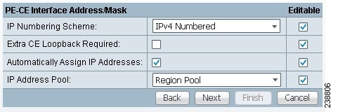
To specify the IP address scheme you want to use for this service policy, perform the following steps.
Step 1 ![]() Define the IP addressing scheme that is appropriate for the PE-CE link.
Define the IP addressing scheme that is appropriate for the PE-CE link.
IP Numbering Scheme
You can choose from the following options.
•![]() IPv4 Numbered
IPv4 Numbered
If you choose IPv4 Numbered and also check the Automatically Assign IP Address check box, Prime Fulfillment: MPLS checks for the presence of the corresponding IP addresses in the router's configuration file. If the addresses are present and they are in the same subnet, Prime Fulfillment uses those addresses (and does not allocate them from the address pool). If the IP addresses are not present in the configuration file, Prime Fulfillment picks IPv4 addresses from a /30 subnet point-to-point IP address pool.
•![]() IPv4 Unnumbered
IPv4 Unnumbered
IPv4 addresses are drawn from the loopback IPv4 address pool. An unnumbered IPv4 address means that each interface "borrows" its address from another interface on the router (usually the loopback interface). Unnumbered addresses can only be used on point-to-point WAN links (such as Serial, Frame, and ATM), not on LAN links (such as Ethernet). If using IP unnumbered, then both the PE and CE must use the same IP unnumbered addressing scheme. When you choose IPv4 Unnumbered, Prime Fulfillment: MPLS creates a static route for the PE-CE link.
When you choose IPv4 Unnumbered, Prime Fulfillment: MPLS automatically creates a loopback interface (unless a loopback interface already exists with the correct attributes). For related information, see Using Existing Loopback Interface Number.
•![]() IPv6 Numbered
IPv6 Numbered
This addressing scheme is provided to support a 6VPE router. See Chapter 23, "IPv6 and 6VPE Support in MPLS VPN" for more information on IPv6 and 6VPE support in MPLS VPN management.
Note ![]() This option only appears if the policy type is a regular PE-CE policy.
This option only appears if the policy type is a regular PE-CE policy.
•![]() IPv4+IPv6 Numbered
IPv4+IPv6 Numbered
In the case of a 6VPE device, the PE interface can be "dual stacked," meaning it can contain both IPv4 and IPv6 addresses. In later steps, you will be able to enter the routing information independently for both IPv4 and IPv6. See Chapter 23, "IPv6 and 6VPE Support in MPLS VPN" for more information on IPv6 and 6VPE support in MPLS VPN management.
Note ![]() This option only appears if the policy type is a regular PE-CE policy.
This option only appears if the policy type is a regular PE-CE policy.
Step 2 ![]() Indicate whether an extra loopback interface is required for the CE.
Indicate whether an extra loopback interface is required for the CE.
Extra CE Loopback Required
Even though a numbered IP address does not require a loopback address, Prime Fulfillment software provides the option to specify than an extra CE loopback interface is required. This option places an IP address on a CE router that is not tied to any physical interface.
If you enable Extra CE Loopback Required, you can enter the CE loopback address.
Step 3 ![]() Specify whether you want to automatically assign IP addresses.
Specify whether you want to automatically assign IP addresses.
Automatically Assign IP Address
If you choose IPv4 Unnumbered and also check the Automatically Assign IP Address check box, Prime Fulfillment picks two IP addresses from a /32 subnet point-to-point IP address pool.
If you choose IPv4 Numbered and also check the Automatically Assign IP Address check box, Prime Fulfillment checks for the presence of the corresponding IP addresses in the router's configuration file. If the addresses are present and they are in the same subnet, Prime Fulfillment uses those addresses (and does not allocate them from the address pool). If the IP addresses are not present in the configuration file, Prime Fulfillment picks IP addresses from a /30 subnet point-to-point IP address pool.
Note ![]() This option is not supported for the IPv6 Numbered and IPv4+IPv6 Numbered address schemes.
This option is not supported for the IPv6 Numbered and IPv4+IPv6 Numbered address schemes.
Step 4 ![]() Specify the IP address pool and its associated Region for this service policy.
Specify the IP address pool and its associated Region for this service policy.
IP Address Pool
The IP Address Pool option gives the service operator the ability to have Prime Fulfillment automatically allocate IP addresses from the IP address pool attached to the Region. Prior to defining this aspect of the service policy, the Region must be defined and the appropriate IP address pools assigned to the Region.
You can specify IP address pool information for point-to-point (IP numbered) PE-CE links.
IP unnumbered addresses are drawn from the loopback IP address pool. An unnumbered IP address means that each interface "borrows" its address from another interface on the router (usually the loopback interface). Unnumbered addresses can only be used on point-to-point WAN links (such as Serial, Frame, and ATM), not on LAN links (such as Ethernet). If using IP unnumbered, then both the PE and CE must use the same IP unnumbered addressing scheme.
Note ![]() This option is not supported for the IPv6 Numbered and IPv4+IPv6 Numbered address schemes.
This option is not supported for the IPv6 Numbered and IPv4+IPv6 Numbered address schemes.
Step 5 ![]() When satisfied with the IP address scheme, click Next.
When satisfied with the IP address scheme, click Next.
Using Existing Loopback Interface Number
On each PE, there is usually only one loopback interface number per VRF for interfaces using IP unnumbered addresses. However, if provisioning an interface using IP unnumbered addresses and manually assigned IP addresses, it is possible to have more than one loopback interface number under the same VRF. When using automatically-assigned IP addresses for provisioning IP unnumbered addresses, Prime Fulfillment associates the first loopback number with the same VRF name to the interface. If no loopback number already exists, Prime Fulfillment creates one.
If a service provider wants Prime Fulfillment to use an existing loopback interface number (for example, Loopback0), the service provider must modify the loopback interface description line in the configuration files for the pertinent routers (PE or CE).
To use the existing loopback interface number, you must modify the loopback interface description line so that it includes the keyword VPN-SC, as shown in the following example of a router configuration file.
Note ![]() When using an existing loopback interface number on a PE, an additional command line with the
When using an existing loopback interface number on a PE, an additional command line with the
ip vrf forwarding VRF_name command must be included directly after the "description" line.
interface Loopback0
description by VPN-SC
ip vrf forwarding <VRF_name> ; This line is required on the PE only
ip address 209.165.202.129 255.255.255.224
You can use an existing loopback interface number only when the interface configuration meets these conditions: it must be a WAN serial interface using IP unnumbered addresses.
Prime Fulfillment selects loopback interface numbers by sequence. Prime Fulfillment uses the first loopback interface number that meets the requirement—for a CE, it is inclusion of the VPN-SC keyword; for a PE, it is the matching VRF name.
For example, if loopback1 and loopback2 include the VPN-SC keyword, but loopback3 does not, adding the VPN-SC keyword to loopback3 will not force Prime Fulfillment to choose loopback3 for the unnumbered interface when using automatically assigned addresses. Loopback1 will be chosen instead. The only way to choose a specific loopback interface number is to use a manually assigned IP address that matches the desired loopback interface number.
Note ![]() Unlike standard interfaces, when loopback interfaces are provisioned in Prime Fulfillment, the resulting configuration file does not include a service request (SR) ID number. This is because multiple interfaces or service requests can use the same loopback interface.
Unlike standard interfaces, when loopback interfaces are provisioned in Prime Fulfillment, the resulting configuration file does not include a service request (SR) ID number. This is because multiple interfaces or service requests can use the same loopback interface.
To continue with the example, see the following section, Specifying the Routing Protocol for a Service.
Specifying the Routing Protocol for a Service
You can now specify the routing protocol information for this service policy, as shown in Figure 24-4.
Note ![]() IPv4 and IPv6 routing are independent. The Prime Fulfillment GUI allows you to input the same or different routing protocols for IPv4 and IPv6, depending upon which addressing scheme you selected. Not all routing protocols are supported for IPv6. See Chapter 23, "IPv6 and 6VPE Support in MPLS VPN" for more information IPv6 and supported routing protocols.
IPv4 and IPv6 routing are independent. The Prime Fulfillment GUI allows you to input the same or different routing protocols for IPv4 and IPv6, depending upon which addressing scheme you selected. Not all routing protocols are supported for IPv6. See Chapter 23, "IPv6 and 6VPE Support in MPLS VPN" for more information IPv6 and supported routing protocols.
The routing protocol you choose must run on both the PE and the CE. You can choose any one of the following protocols:
•![]() Static—Specifies a static route (see Static Protocol Chosen).
Static—Specifies a static route (see Static Protocol Chosen).
•![]() RIP—Routing Information Protocol (see RIP Protocol Chosen).
RIP—Routing Information Protocol (see RIP Protocol Chosen).
•![]() BGP—Border Gateway Protocol (see BGP Protocol Chosen).
BGP—Border Gateway Protocol (see BGP Protocol Chosen).
•![]() OSPF—Open Shortest Path First (see OSPF Protocol Chosen).
OSPF—Open Shortest Path First (see OSPF Protocol Chosen).
•![]() EIGRP—Enhanced Interior Gateway Routing Protocol (see EIGRP Protocol Chosen).
EIGRP—Enhanced Interior Gateway Routing Protocol (see EIGRP Protocol Chosen).
•![]() None—Specifies parameters for cable services (see None Chosen: Cable Services).
None—Specifies parameters for cable services (see None Chosen: Cable Services).
To specify a routing protocol for the PE-CE link, perform the following steps.
Step 1 ![]() Choose the appropriate protocol from the Routing Protocol drop-down list.
Choose the appropriate protocol from the Routing Protocol drop-down list.
Note ![]() In the case of IPv6 addressing, only a subset of routing protocols are supported. For IOS XR devices, only Static, BGP, EIGRP and None are supported. For IOS devices, only Static, BGP, and None are supported.
In the case of IPv6 addressing, only a subset of routing protocols are supported. For IOS XR devices, only Static, BGP, EIGRP and None are supported. For IOS devices, only Static, BGP, and None are supported.
When you choose a particular routing protocol, the related parameters for that protocol are displayed.
Step 2 ![]() Enter the required information for the selected routing protocol, then click Next.
Enter the required information for the selected routing protocol, then click Next.
Step 3 ![]() Define the MPLS Policy VRF and VPN Selection parameters as described in Defining VRF and VPN Information.
Define the MPLS Policy VRF and VPN Selection parameters as described in Defining VRF and VPN Information.
Redistribution of IP Routes
Route redistribution is the process of taking routing information from one source and importing that information into another source. Redistribution should be approached with caution. When you perform route redistribution, you lose information. Metrics must be arbitrarily reset. For example, if a group of RIP routes with a metric of five hops is redistributed into iGRP, there is no way to translate the five hop RIP metric into the composite metric of IGRP. You must arbitrarily choose a metric for the RIP routes as they are redistributed into IGRP. Also, when redistribution is performed at two or more points between two dynamic routing protocol domains, routing loops can occur.
CSC Support
To define a Service Policy with Carrier Supporting Carrier (CSC), choose the CSC Support check box from the MPLS Policy Editor - Routing Information. When CSC Support is checked, the CSC functionality is enabled to the MPLS VPN service. Provisioning CSC is explained in Chapter 30, "Provisioning Carrier Supporting Carrier."
Giving Only Default Routes to CE
When you enable the Give only default routes to CE option, you indicate whether the site needs full routing or default routing. Full routing is when the site must know specifically which other routes are present in the VPN. Default routing is when it is sufficient to send all packets that are not specifically for your site to the VPN.
If you choose this option, Prime Fulfillment configures the default-info originate command on the PE router under the running protocol (for RIP, OSPF, or EIGRP). For Static, Prime Fulfillment configures an ip route 0.0.0.0 0.0.0.0 <out-going interface name> command on the CE router.
A device can only have one default route. Therefore, the VPN can use a default route, but only on condition that the customer site does not already have a different one. The most common reason to already have a default route is that the site has an Internet feed that is independent of the VPN.
If the CE site already has Internet service, the CE can either route all packets to unknown destinations to the Internet or learn all the routes in the Internet. The obvious choice is to route all packets to unknown destinations to the Internet. If a site has an Internet feed, it might already have a default route. Under such conditions, setting the VPN as the default route is incorrect; the VPN should only route packets meant for other VPN sites.
Static Protocol Chosen
Static routing refers to routes to destinations that are listed manually in the router. Network reachability in this case is not dependent on the existence and state of the network itself. Whether a destination is up or down, the static routes remain in the routing table and traffic is still sent to that destination.
When you choose Static as the protocol, four options are enabled: CSC Support, Give Only Default Routes to CE, Redistribute Connected (BGP only), and Default Information Originate (BGP only), as shown in Figure 24-4.
Note ![]() Two other options (AdvertisedRoutes and Default Routes - Routes to reach other sites) are available when you create the service request. See Setting Static Routing Protocol Attributes (for IPv4 and IPv6), page 25-16.
Two other options (AdvertisedRoutes and Default Routes - Routes to reach other sites) are available when you create the service request. See Setting Static Routing Protocol Attributes (for IPv4 and IPv6), page 25-16.
Figure 24-4 Specifying the Static Routing Protocol
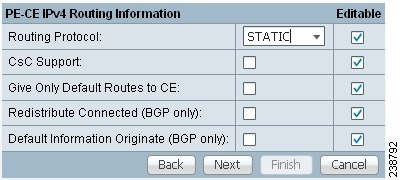
To specify Static as the routing protocol for the service policy, perform the following steps.
Step 1 ![]() CsC Support: To define a Service Policy with Carrier Supporting Carrier (CSC), choose the CSC Support check box from the MPLS Policy Editor - Routing Information.
CsC Support: To define a Service Policy with Carrier Supporting Carrier (CSC), choose the CSC Support check box from the MPLS Policy Editor - Routing Information.
When CSC Support is checked, the CSC functionality is enabled to the MPLS VPN service. Provisioning CSC is explained in Chapter 30, "Provisioning Carrier Supporting Carrier."
This attribute is not available if the IP addressing scheme was set to IPv6 in previous steps.
Step 2 ![]() Give Only Default Routes to CE: Specify whether this service policy should give only default routes to the CE when provisioning with static routes.
Give Only Default Routes to CE: Specify whether this service policy should give only default routes to the CE when provisioning with static routes.
When you enable the Give only default routes to CE option with static route provisioning on the PE-CE link, Prime Fulfillment creates a default route on the CE that points to the PE. The VRF static route to the CE site is redistributed into BGP to other sites in the VPN.
When you choose this option, the default route (0.0.0.0/32) is automatically configured; the site contains no Internet feed or any other requirement for a default route. When the site encounters a packet that does not route locally, it can send the packet to the VPN.
If you choose this option, Prime Fulfillment configures the default-info originate command on the PE router under the running protocol (for RIP, OSPF, or EIGRP). For Static, Prime Fulfillment configures an ip route 0.0.0.0 0.0.0.0 <out-going interface name> command on the CE router.
Step 3 ![]() Redistribute Connected (BGP Only): Indicate whether this service policy should redistribute the connected routes to the other CEs in the VPN.
Redistribute Connected (BGP Only): Indicate whether this service policy should redistribute the connected routes to the other CEs in the VPN.
When you enable the Redistribute Connected option, the connected routes (that is, the routes to the directly connected PEs or CEs) are distributed to all the other CEs in that particular VPN. This option is meant for iBGP if the routing protocol between PE-CE is a non-BGP protocol. For example, if the routing protocol is RIP, OSPF, EIGRP, or Static, the option is meant for the router BGP that is configured on the PE for the MPLS core. On the PE router, there is one router BGP process running at all times for MPLS. This option is also for BGP.
Tip ![]() You must enable the Redistribute Connected option when joining the management VPN and you are also using IP numbered addresses.
You must enable the Redistribute Connected option when joining the management VPN and you are also using IP numbered addresses.
Step 4 ![]() Default Information Originate (BGP Only): When you enable this option, Prime Fulfillment issues a default-information-originate command under the iBGP address family for the currently specified VRF.
Default Information Originate (BGP Only): When you enable this option, Prime Fulfillment issues a default-information-originate command under the iBGP address family for the currently specified VRF.
The Default Information Originate option is required, especially in the hub and spoke topology because each spoke must be able to communicate with every other spoke (by injecting a default route in the hub PE to the spoke PEs).
Step 5 ![]() When finished defining static routing for this service policy, click Next.
When finished defining static routing for this service policy, click Next.
The MPLS Policy VRF and VPN Membership dialog box appears. To proceed, see Defining VRF and VPN Information.
RIP Protocol Chosen
The Routing Information Protocol (RIP) is a distance-vector protocol that uses hop count as its metric. RIP is an Interior Gateway Protocol (IGP), which means that it performs routing within a single autonomous system. RIP sends routing-update messages at regular intervals and when the network topology changes. When a router receives a routing update that includes changes to an entry, it updates its routing table to reflect the new route. The metric value for the path is increased by one, and the sender is specified as the next hop.
RIP routers maintain only the best route to a destination—that is, the route with the lowest possible metric value. After updating its routing table, the router immediately begins transmitting routing updates to inform other network routers of the change. These updates are sent independently of the regularly scheduled updates that RIP routers transmit.
To specify RIP as the routing protocol for the service policy, perform the following steps.
Step 1 ![]() Choose RIP from the Routing Protocol drop-down list.
Choose RIP from the Routing Protocol drop-down list.
The RIP Routing Protocol dialog box appears, as shown in Figure 24-5.
Figure 24-5 RIP Selected as the Routing Protocol
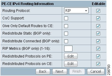
Step 2 ![]() CSC Support: To define a Service Policy with Carrier Supporting Carrier (CSC), choose the CSC Support check box from the MPLS Policy Editor - Routing Information.
CSC Support: To define a Service Policy with Carrier Supporting Carrier (CSC), choose the CSC Support check box from the MPLS Policy Editor - Routing Information.
When CSC Support is checked, the CSC functionality is enabled to the MPLS VPN service. Provisioning CSC is explained in Chapter 30, "Provisioning Carrier Supporting Carrier."
Step 3 ![]() Give Only Default Routes to CE: Specify whether you want to give only the default routes to the CE.
Give Only Default Routes to CE: Specify whether you want to give only the default routes to the CE.
When an internetwork is designed hierarchically, default routes are a useful tool to limit the need to propagate routing information. Access-level networks, such as branch offices, typically have only one connection to headquarters. Instead of advertising all of an organization's network prefixes to a branch office, configure a default route. If a destination prefix is not in a branch office's routing table, forward the packet over the default route. The Cisco IP routing table displays the default route at the top of the routing table as the "Gateway of Last Resort." RIP automatically redistributes the 0.0.0.0 0.0.0.0 route.
If you choose this option, Prime Fulfillment configures the default-info originate command on the PE router under the running protocol (for RIP, OSPF, or EIGRP). For Static, Prime Fulfillment configures an ip route 0.0.0.0 0.0.0.0 <out-going interface name> command on the CE router.
When you enable the Give Only Default Routes to CE option for RIP, Prime Fulfillment creates a default RIP route on the PE; the default RIP route points to the PE and is sent to the CE. The provisioning request gives you the option of redistributing any other routing protocols in the customer network into the CE RIP routing protocol. The RIP routes on the PE to the CE site are redistributed into BGP to other VPN sites.
When you choose this option for RIP routing, the PE instructs the CE to send any traffic it cannot route any other way to the PE. Do not use this option if the CE site needs a default route for any reason, such as having a separate Internet feed.
Step 4 ![]() Redistribute Static: (BGP and RIP) Specify whether you want to redistribute static routes into the core BGP network.
Redistribute Static: (BGP and RIP) Specify whether you want to redistribute static routes into the core BGP network.
When you enable the Redistribute Static option for RIP, the software imports the static routes into the core network (running BGP) and to the CE (running RIP).
Step 5 ![]() Redistribute Connected: (BGP only) Specify whether you want to redistribute the connected routes to the CEs in the VPN.
Redistribute Connected: (BGP only) Specify whether you want to redistribute the connected routes to the CEs in the VPN.
When you enable the Redistribute Connected option for BGP, the software imports the connected routes (that is, the routes to the directly connected PEs or CEs) to all the other CEs in that particular VPN.
When you enable the Redistribute Connected option, the connected routes (that is, the routes to the directly connected PEs or CEs) are distributed to all the other CEs in that particular VPN. This option is meant for iBGP if the routing protocol between PE-CE is a non-BGP protocol. For example, if the routing protocol is RIP, OSPF, EIGRP, or Static, the option is meant for the router BGP that is configured on the PE for the MPLS core. On the PE router, there is one router BGP process running at all times for MPLS. This option is also for BGP.
Step 6 ![]() RIP Metrics: (BGP only) Enter the appropriate RIP metric value. The valid metric values are 1 through 16.
RIP Metrics: (BGP only) Enter the appropriate RIP metric value. The valid metric values are 1 through 16.
The metrics used by RIP are hop counts. The hop count for all directly connected interfaces is 1. If an adjacent router advertises a route to another network with a hop count of 1, then the metric for that network is 2, since the source router must send a packet to that router to get to the destination network.
As each router sends its routing tables to its neighbors, a route can be determined to each network within the AS. If there are multiple paths within the AS from a router to a network, the router selects the path with the smallest hop count and ignores the other paths.
Step 7 ![]() Redistributed Protocols on PE: Specify whether you want to redistribute the routing protocols into the PE.
Redistributed Protocols on PE: Specify whether you want to redistribute the routing protocols into the PE.
Redistribution allows routing information discovered through another routing protocol to be distributed in the update messages of the current routing protocol. With redistribution, you can reach all the points of your IP internetwork. When a RIP router receives routing information from another protocol, it updates all of its RIP neighbors with the new routing information already discovered by the protocol it imports redistribution information from.
To specify the protocols that RIP needs to import routing information to the PE:
a. ![]() From the Redistribute Protocols on PE option, click Edit.
From the Redistribute Protocols on PE option, click Edit.
The PE Redistributed Protocol dialog box appears.
b. ![]() Click Add.
Click Add.
The PE Redistributed Protocols dialog box appears.
c. ![]() From the Protocol Type drop-down list, choose the protocol you want to import into the PE.
From the Protocol Type drop-down list, choose the protocol you want to import into the PE.
You can choose one of the following: Static, OSPF, or EIGRP.
•![]() Redistribute Static. When you choose Static routes for redistribution into RIP, Prime Fulfillment imports the static routes into the PE that is running RIP.
Redistribute Static. When you choose Static routes for redistribution into RIP, Prime Fulfillment imports the static routes into the PE that is running RIP.
There are no parameters or metrics required for redistributing Static routes into the PE.
•![]() Redistribute OSPF (Open Shortest Path First). When you choose the OSPF protocol for redistribution into RIP, Prime Fulfillment imports the OSPF routes into the PE that is running RIP.
Redistribute OSPF (Open Shortest Path First). When you choose the OSPF protocol for redistribution into RIP, Prime Fulfillment imports the OSPF routes into the PE that is running RIP.
Parameter: OSPF process number
Metric: Any numeral from 1 to 16
•![]() Redistribute EIGRP (Enhanced IGRP). When you choose the EIGRP protocol for redistribution into RIP, Prime Fulfillment imports the EIGRP routes into the PE that is running RIP.
Redistribute EIGRP (Enhanced IGRP). When you choose the EIGRP protocol for redistribution into RIP, Prime Fulfillment imports the EIGRP routes into the PE that is running RIP.
Parameter: EIGRP autonomous system (AS) number
Metric: Any numeral from 1 to 16
d. ![]() Choose the protocol you want to redistribute into RIP on the PE.
Choose the protocol you want to redistribute into RIP on the PE.
e. ![]() Enter the appropriate parameter for the protocol selected.
Enter the appropriate parameter for the protocol selected.
f. ![]() Click Add.
Click Add.
g. ![]() Repeat these steps for any additional protocols you want to redistribute into RIP on the PE, then click OK.
Repeat these steps for any additional protocols you want to redistribute into RIP on the PE, then click OK.
Step 8 ![]() Redistribute Protocols on CE: Specify whether you want to redistribute the routing protocols into the CE.
Redistribute Protocols on CE: Specify whether you want to redistribute the routing protocols into the CE.
To specify the protocols that RIP needs to import routing information to the CE:
a. ![]() From the Redistribute Protocols on CE option, click Edit.
From the Redistribute Protocols on CE option, click Edit.
The CE Redistributed Protocol dialog box appears.
b. ![]() Click Add.
Click Add.
The CE Redistributed Protocols dialog box appears.
c. ![]() From the Protocol Type drop-down list, choose the protocol you want to import into the CE.
From the Protocol Type drop-down list, choose the protocol you want to import into the CE.
You can choose one of the following protocols: Static, BGP, Connected (routes), IGRP, OSPF, EIGRP, or IS-IS.
•![]() Redistribute Static. When you choose Static routes for redistribution into RIP, Prime Fulfillment imports the static routes into the CE that is running RIP.
Redistribute Static. When you choose Static routes for redistribution into RIP, Prime Fulfillment imports the static routes into the CE that is running RIP.
There are no parameters required for redistributing Static routes into the CE.
•![]() Redistribute BGP (Border Gateway Protocol). When you choose the BGP protocol for redistribution into RIP, Prime Fulfillment imports the BGP routes into the CE that is running RIP.
Redistribute BGP (Border Gateway Protocol). When you choose the BGP protocol for redistribution into RIP, Prime Fulfillment imports the BGP routes into the CE that is running RIP.
Parameter: BGP autonomous system (AS) number
•![]() Redistribute Connected routes. When you choose the Connected routes for redistribution into RIP, Prime Fulfillment imports all the routes to the interfaces connected to the current router. Use the Connected option when you want to advertise a network, but you don't want to send routing updates into that network. Note that redistributing connected routes indiscriminately redistributes all connected routes into the routing domain.
Redistribute Connected routes. When you choose the Connected routes for redistribution into RIP, Prime Fulfillment imports all the routes to the interfaces connected to the current router. Use the Connected option when you want to advertise a network, but you don't want to send routing updates into that network. Note that redistributing connected routes indiscriminately redistributes all connected routes into the routing domain.
Parameter: No parameter required
•![]() Redistribute IGRP (Interior Gateway Routing Protocol). When you choose the IGRP (Interior Gateway Routing) protocol for redistribution into RIP, Prime Fulfillment imports the IGRP routes into the CE that is running RIP.
Redistribute IGRP (Interior Gateway Routing Protocol). When you choose the IGRP (Interior Gateway Routing) protocol for redistribution into RIP, Prime Fulfillment imports the IGRP routes into the CE that is running RIP.
Parameter: IGRP autonomous system (AS) number
•![]() Redistribute EIGRP (Enhanced IGRP). When you choose the EIGRP protocol for redistribution into RIP, Prime Fulfillment imports the EIGRP routes into the PE that is running RIP.
Redistribute EIGRP (Enhanced IGRP). When you choose the EIGRP protocol for redistribution into RIP, Prime Fulfillment imports the EIGRP routes into the PE that is running RIP.
Parameter: EIGRP autonomous system (AS) number
•![]() Redistribute OSPF (Open Shortest Path First). When you choose the OSPF protocol for redistribution into RIP, Prime Fulfillment imports the OSPF routes into the CE that is running RIP.
Redistribute OSPF (Open Shortest Path First). When you choose the OSPF protocol for redistribution into RIP, Prime Fulfillment imports the OSPF routes into the CE that is running RIP.
Parameter: OSPF process number
•![]() Redistribute IS-IS (Intermediate System-to-Intermediate System. When you choose the IS-IS protocol for redistribution into RIP, Prime Fulfillment imports the IS-IS routes into the CE that is running RIP.
Redistribute IS-IS (Intermediate System-to-Intermediate System. When you choose the IS-IS protocol for redistribution into RIP, Prime Fulfillment imports the IS-IS routes into the CE that is running RIP.
Parameter: IS-IS tag number
d. ![]() Choose the protocol you want to redistribute into RIP on the CE.
Choose the protocol you want to redistribute into RIP on the CE.
e. ![]() Enter the appropriate parameter for the selected protocol.
Enter the appropriate parameter for the selected protocol.
f. ![]() Click Add.
Click Add.
g. ![]() Repeat these steps for any additional protocols you want to redistribute into RIP on the CE, then click OK.
Repeat these steps for any additional protocols you want to redistribute into RIP on the CE, then click OK.
Step 9 ![]() When you are satisfied with the RIP protocol settings for this service policy, click Next.
When you are satisfied with the RIP protocol settings for this service policy, click Next.
The MPLS Policy VRF and VPN Membership dialog box appears. To proceed, see Defining VRF and VPN Information.
Note ![]() If a PE link is initially configured to use the RIP routing protocol and subsequently modified to use another routing protocol (or static routing), Prime Fulfillment does not remove all of the RIP CLI commands associated with the interface from the PE configuration file. Specifically, Prime Fulfillment does not remove the address family subcommands under the RIP command unless the VRF associated with the service request is removed. This is because Prime Fulfillment configures the RIP protocol using a network class (that is, network a.0.0.0) based under address-family. Later, if the routing protocol is changed, Prime Fulfillment does not remove any other services under the same network.
If a PE link is initially configured to use the RIP routing protocol and subsequently modified to use another routing protocol (or static routing), Prime Fulfillment does not remove all of the RIP CLI commands associated with the interface from the PE configuration file. Specifically, Prime Fulfillment does not remove the address family subcommands under the RIP command unless the VRF associated with the service request is removed. This is because Prime Fulfillment configures the RIP protocol using a network class (that is, network a.0.0.0) based under address-family. Later, if the routing protocol is changed, Prime Fulfillment does not remove any other services under the same network.
BGP Protocol Chosen
BGP (Border Gateway Protocol) operates over TCP (Transmission Control Protocol), using port 179. By using TCP, BGP is assured of reliable transport, so the BGP protocol itself lacks any form of error detection or correction (TCP performs these functions). BGP can operate between peers that are separated by several intermediate hops, even when the peers are not necessarily running the BGP protocol.
BGP operates in one of two modes: Internal BGP (iBGP) or External BGP (eBGP). The protocol uses the same packet formats and data structures in either case. iBGP is used between BGP speakers within a single autonomous system, while eBGP operates over inter-AS links.
eBGP extensions are supported for IPv6 and dual stacked services. The eBGP extensions are configured per BGP neighbor. Thus, the IPv4 and IPv6 neighbors for the same VRF can be configured with a different set of values. Prime Fulfillment facilitates this by allowing these parameters to be configured per BGP neighbor.
To specify BGP as the routing protocol for the service policy, perform the following steps.
Step 1 ![]() Choose BGP from the Routing Protocol drop-down list.
Choose BGP from the Routing Protocol drop-down list.
The BGP Routing Protocol dialog box appears, as shown in Figure 24-6.
Figure 24-6 BGP Selected as the Routing Protocol
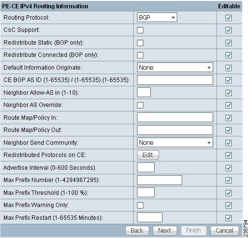
Step 2 ![]() CsC Support: To define a Service Policy with Carrier Supporting Carrier (CSC), check the CSC Support check box from the MPLS Policy Editor - Routing Information.
CsC Support: To define a Service Policy with Carrier Supporting Carrier (CSC), check the CSC Support check box from the MPLS Policy Editor - Routing Information.
When CSC Support is checked, the CSC functionality is enabled to the MPLS VPN service. Provisioning CSC is explained in Chapter 30, "Provisioning Carrier Supporting Carrier."
This attribute is not available if the IP addressing scheme was set to IPv6 in previous steps.
Step 3 ![]() Redistribute Static (BGP Only): Indicate whether you want to redistribute static routes into BGP.
Redistribute Static (BGP Only): Indicate whether you want to redistribute static routes into BGP.
If you are importing static routes into BGP, choose this check box.
Step 4 ![]() Redistribute Connected Routes (BGP Only): Indicate whether you want to redistribute the directly connected routes into BGP.
Redistribute Connected Routes (BGP Only): Indicate whether you want to redistribute the directly connected routes into BGP.
Enabling the Redistribute Connected option imports all the routes to the interfaces connected to the current router. Use the Redistribute Connected option when you want to advertise a network, but you don't want to send routing updates into that network. Note that redistributing connected routes indiscriminately redistributes all connected routes into the routing domain.
When you enable the Redistribute Connected option, the connected routes (that is, the routes to the directly connected PEs or CEs) are distributed to all the other CEs in that particular VPN. This option is meant for iBGP if the routing protocol between PE-CE is a non-BGP protocol. For example, if the routing protocol is RIP, OSPF, EIGRP, or Static, the option is meant for the router BGP that is configured on the PE for the MPLS core. On the PE router, there is one router BGP process running at all times for MPLS. This option is also for BGP.
Step 5 ![]() Default Information Originate: Choose an appropriate option from the drop-down list to cause the BGP speaker (local router) to send a default route to a neighbor.
Default Information Originate: Choose an appropriate option from the drop-down list to cause the BGP speaker (local router) to send a default route to a neighbor.
This inserts the default-originate command under the per-neighbor configuration.
The drop-down list has three choices:
–![]() None. This is the default choice. The default-origination command is not added to the per-neighbor configuration. The default route is not advertised to BGP neighbors.
None. This is the default choice. The default-origination command is not added to the per-neighbor configuration. The default route is not advertised to BGP neighbors.
–![]() Enable. Allows you to specify the name of a route policy in the Route-Policy (Default Information Origination) field, which dynamically appears in the Prime Fulfillment GUI. The route policy allows route 0.0.0.0 to be injected conditionally. See the usage notes below for further details.
Enable. Allows you to specify the name of a route policy in the Route-Policy (Default Information Origination) field, which dynamically appears in the Prime Fulfillment GUI. The route policy allows route 0.0.0.0 to be injected conditionally. See the usage notes below for further details.
–![]() Disable. Prevents the default-originate command characteristics from being inherited from a parent group.
Disable. Prevents the default-originate command characteristics from being inherited from a parent group.
Usage notes:
•![]() Entering a route policy in the Route-Policy (Default Information Origination) field is optional.
Entering a route policy in the Route-Policy (Default Information Origination) field is optional.
•![]() Any route policy that is specified must be pre-existing on the device. If not, Prime Fulfillment will generate an error message when a service request based on the policy is created.
Any route policy that is specified must be pre-existing on the device. If not, Prime Fulfillment will generate an error message when a service request based on the policy is created.
•![]() The default-originate command does not require the presence of the default route (0.0.0.0/0 for IPv4 or ::/0 for IPv6) in the local router. When the default-originate command is used with a route policy, the default route is advertised if any route in the BGP table matches the policy.
The default-originate command does not require the presence of the default route (0.0.0.0/0 for IPv4 or ::/0 for IPv6) in the local router. When the default-originate command is used with a route policy, the default route is advertised if any route in the BGP table matches the policy.
•![]() The Default Information Originate attribute is supported in MPLS policies and service requests for both IPv4 and IPv6 address families. It is only supported for MPLS PE_CE and PE_No_CE policies and service requests. It is not supported in MVRFCE policies and service requests.
The Default Information Originate attribute is supported in MPLS policies and service requests for both IPv4 and IPv6 address families. It is only supported for MPLS PE_CE and PE_No_CE policies and service requests. It is not supported in MVRFCE policies and service requests.
•![]() The Default Information Originate attribute is only supported on IOS XR devices.
The Default Information Originate attribute is only supported on IOS XR devices.
•![]() The following Prime Fulfillment template variables support this feature:
The following Prime Fulfillment template variables support this feature:
–![]() For IPv4: PE_CE_NBR_DEFAULT_INFO_ORIGINATE_ROUTE_POLICY
For IPv4: PE_CE_NBR_DEFAULT_INFO_ORIGINATE_ROUTE_POLICY
–![]() For IPv4: PE_CE_NBR_DEFAULT_INFO_ORIGINATE
For IPv4: PE_CE_NBR_DEFAULT_INFO_ORIGINATE
–![]() For IPv6: PE_CE_NBR_DEFAULT_INFO_ORIGINATE_ROUTE_POLICY_IPV6
For IPv6: PE_CE_NBR_DEFAULT_INFO_ORIGINATE_ROUTE_POLICY_IPV6
–![]() For IPv6: PE_CE_NBR_DEFAULT_INFO_ORIGINATE_IPV6
For IPv6: PE_CE_NBR_DEFAULT_INFO_ORIGINATE_IPV6
•![]() For sample configlets showing the use of the Default Information Originate option, see Chapter 33, "PE L3 MPLS VPN (BGP, Default Information Originate, IOS XR)".
For sample configlets showing the use of the Default Information Originate option, see Chapter 33, "PE L3 MPLS VPN (BGP, Default Information Originate, IOS XR)".
Step 6 ![]() CE BGP AS ID: Enter the BGP autonomous system (AS) number for the customer's BGP network.
CE BGP AS ID: Enter the BGP autonomous system (AS) number for the customer's BGP network.
The autonomous number assigned here to the CE must be different from the BGP AS number for the service provider's core network.
2-byte integer values are supported as valid AS number values. In addition, Prime Fulfillment supports a remote 4-byte AS number in the format [0-65535].[0-65535]. As an example: 100.65535. This remote 4-byte AS number is supported as a CE BGP AS number in a service policy and in a service request. If the platform does not support a remote 4-byte AS number, the service deployment fails. The remote 4-byte AS number is not supported on IOS platforms, but is supported on IOS XR (for both IPv4 and IPv6 services).
Step 7 ![]() Neighbor Allow-AS In: If appropriate, enter the Neighbor Allow-AS-in value.
Neighbor Allow-AS In: If appropriate, enter the Neighbor Allow-AS-in value.
When you enter a Neighbor Allow-AS-in value, you specify a maximum number of times (up to 10) that the service provider autonomous system (AS) number can occur in the autonomous system path.
Step 8 ![]() Neighbor AS Override: If required for this VPN, enable the Neighbor AS Override option.
Neighbor AS Override: If required for this VPN, enable the Neighbor AS Override option.
The AS Override feature allows the MPLS VPN service provider to run the BGP routing protocol with a customer even if the customer is using the same AS number at different sites. This feature can be used if the VPN customer uses either a private or public autonomous system number.
When you enable the Neighbor AS-Override option, you configure VPN Solutions Center to reuse the same AS number on all the VPN's sites.
Step 9 ![]() Route Map/Policy In: Enter a route map (IOS devices) or route policy (IOS XR devices) to apply to inbound routes.
Route Map/Policy In: Enter a route map (IOS devices) or route policy (IOS XR devices) to apply to inbound routes.
See the usage notes following Step 10 for more information on this attribute.
Note ![]() This attribute is not supported for use with MVRFCE policies and service requests.
This attribute is not supported for use with MVRFCE policies and service requests.
Step 10 ![]() Route Map/Policy Out: Enter a route map (IOS devices) or route policy (IOS XR devices) to apply to outbound routes.
Route Map/Policy Out: Enter a route map (IOS devices) or route policy (IOS XR devices) to apply to outbound routes.
Note ![]() This attribute is not supported for use with MVRFCE policies and service requests. It is also not supported for IPv6 on IOS devices in service requests.
This attribute is not supported for use with MVRFCE policies and service requests. It is also not supported for IPv6 on IOS devices in service requests.
Usage notes for IOS devices (BGP route map):
•![]() The Route Map/Policy In and Route Map/Policy Out attributes are available to support route-map commands for IOS devices with BGP as the PE-CE protocol. They are used to apply a route map to inbound or outbound routes for the purpose of route filtering.
The Route Map/Policy In and Route Map/Policy Out attributes are available to support route-map commands for IOS devices with BGP as the PE-CE protocol. They are used to apply a route map to inbound or outbound routes for the purpose of route filtering.
•![]() The value entered in the text field translates to the neighbor route-map command in address family or router configuration mode, as shown in the following example configuration:
The value entered in the text field translates to the neighbor route-map command in address family or router configuration mode, as shown in the following example configuration:
neighbor x.x.x.x route-map slmpls-in in
neighbor x.x.x.x route-map no-routes out
•![]() These attributes are optional. For IOS devices, no default value is required.
These attributes are optional. For IOS devices, no default value is required.
•![]() The following Prime Fulfillment template variables support BGP route map for IOS devices:
The following Prime Fulfillment template variables support BGP route map for IOS devices:
–![]() PE_CE_NBR_ROUTE_MAP_IN_NAME
PE_CE_NBR_ROUTE_MAP_IN_NAME
–![]() PE_CE_NBR_ROUTE_MAP_OUT_NAME
PE_CE_NBR_ROUTE_MAP_OUT_NAME
•![]() At the service request level, the Route Map/Policy In attribute is disabled and cleared if Site of Origin is enabled. The Site of Origin attribute does not show up at the policy level, but only in the service request workflow (and only in the case of an IOS device and a configuration consisting of a PE with no CE). For additional information on this behavior, see the usage notes for the Site of Origin attribute on page 25-27.
At the service request level, the Route Map/Policy In attribute is disabled and cleared if Site of Origin is enabled. The Site of Origin attribute does not show up at the policy level, but only in the service request workflow (and only in the case of an IOS device and a configuration consisting of a PE with no CE). For additional information on this behavior, see the usage notes for the Site of Origin attribute on page 25-27.
Usage notes for IOS XR devices (route policy):
•![]() The Route Map/Policy In and Route Map/Policy Out attributes are available to support route-policy commands for IOS XR devices. They provide a way to apply a routing policy to updates advertised to or received from a Border Gateway Protocol (BGP) neighbor. The policy filters routes or modifies route attributes.You specify the name of a routing policy for an inbound or outbound route.
The Route Map/Policy In and Route Map/Policy Out attributes are available to support route-policy commands for IOS XR devices. They provide a way to apply a routing policy to updates advertised to or received from a Border Gateway Protocol (BGP) neighbor. The policy filters routes or modifies route attributes.You specify the name of a routing policy for an inbound or outbound route.
•![]() There are globally defined route policies that can be referred to (for example, "pass all"), but the Route Map/Policy In and Route Map/Policy Out attributes provide a means for you to override these with your own specific route policies.
There are globally defined route policies that can be referred to (for example, "pass all"), but the Route Map/Policy In and Route Map/Policy Out attributes provide a means for you to override these with your own specific route policies.
•![]() The actual route policy must be configured externally on the device, prior to creating a service request based on the policy.
The actual route policy must be configured externally on the device, prior to creating a service request based on the policy.
•![]() The in/out values from the GUI are inserted into the IOS XR device configuration, as follows:
The in/out values from the GUI are inserted into the IOS XR device configuration, as follows:
route-policy <IN param> in
route-policy <OUT param> out
•![]() These attributes are optional. For IOS XR devices, if no values are supplied, they default to the DEFAULT value.
These attributes are optional. For IOS XR devices, if no values are supplied, they default to the DEFAULT value.
•![]() The following Prime Fulfillment template variables support Prime Fulfillment route policy commands for IOS XR devices:
The following Prime Fulfillment template variables support Prime Fulfillment route policy commands for IOS XR devices:
–![]() PE_CE_BGP_Neighbor _Route_Map_Or_Policy_In
PE_CE_BGP_Neighbor _Route_Map_Or_Policy_In
–![]() PE_CE_BGP_Neighbor _ Route_Map _Or_Policy_Out
PE_CE_BGP_Neighbor _ Route_Map _Or_Policy_Out
Step 11 ![]() Neighbor Send Community: Choose one of the following from the drop-down list to send a communities attribute to a BGP neighbor:
Neighbor Send Community: Choose one of the following from the drop-down list to send a communities attribute to a BGP neighbor:
•![]() None. Do not send a community attribute to a BGP neighbor.
None. Do not send a community attribute to a BGP neighbor.
•![]() Standard. Send only standard communities to a BGP neighbor.
Standard. Send only standard communities to a BGP neighbor.
•![]() Extended. Send only extended communities to a BGP neighbor.
Extended. Send only extended communities to a BGP neighbor.
•![]() Both. Send both standard and extended communities to a BGP neighbor.
Both. Send both standard and extended communities to a BGP neighbor.
This option is only available when the PE-CE routing protocol is BGP. It is applicable for both IOS and IOS XR devices. It is available for both IPv4 and IPv6 external BGP (eBGP) neighbors.
Note ![]() This attribute is not supported for use with MVRFCE policies and service requests.
This attribute is not supported for use with MVRFCE policies and service requests.
Step 12 ![]() Specify whether you want to redistribute routing protocols into the CE.
Specify whether you want to redistribute routing protocols into the CE.
Redistributed Protocols on CE: The redistribution of routes into MP-iBGP is necessary only when the routes are learned through any means other than BGP between the PE and CE routers. This includes connected subnets and static routes. In the case of routes learned via BGP from the CE, redistribution is not required because it's performed automatically.
To specify the protocols that BGP needs to import routing information to the CE:
a. ![]() From the Redistribute Protocols on CE option, click Edit.
From the Redistribute Protocols on CE option, click Edit.
The CE Redistributed Protocol dialog box appears.
b. ![]() Click Add.
Click Add.
The CE Redistributed Protocols dialog box appears.
c. ![]() From the Protocol Type drop-down list, choose the protocol you want to import into the CE.
From the Protocol Type drop-down list, choose the protocol you want to import into the CE.
You can choose one of the following protocols: Static, RIP, Connected (routes), IGRP, OSPF, EIGRP, or IS-IS.
•![]() Redistribute Static. When you choose Static routes for redistribution into BGP, Prime Fulfillment imports the static routes into the CE that is running BGP.
Redistribute Static. When you choose Static routes for redistribution into BGP, Prime Fulfillment imports the static routes into the CE that is running BGP.
Parameter: No parameter required
•![]() Redistribute RIP (Routing Information Protocol). When you choose the RIP protocol for redistribution into BGP, Cisco Prime Fulfillment imports the RIP routes into the CE that is running BGP.
Redistribute RIP (Routing Information Protocol). When you choose the RIP protocol for redistribution into BGP, Cisco Prime Fulfillment imports the RIP routes into the CE that is running BGP.
Parameter: No parameter required
•![]() Redistribute Connected routes. When you choose the Connected routes for redistribution into BGP, Prime Fulfillment imports all the routes to the interfaces connected to the current router. Use the Connected option when you want to advertise a network, but you do not want to send routing updates into that network. Note that redistributing connected routes indiscriminately redistributes all connected routes into the routing domain.
Redistribute Connected routes. When you choose the Connected routes for redistribution into BGP, Prime Fulfillment imports all the routes to the interfaces connected to the current router. Use the Connected option when you want to advertise a network, but you do not want to send routing updates into that network. Note that redistributing connected routes indiscriminately redistributes all connected routes into the routing domain.
Parameter: No parameter required
•![]() Redistribute IGRP (Interior Gateway Routing Protocol). When you choose the IGRP protocol for redistribution into BGP, IP Solution Center imports the IGRP routes into the CE that is running BGP.
Redistribute IGRP (Interior Gateway Routing Protocol). When you choose the IGRP protocol for redistribution into BGP, IP Solution Center imports the IGRP routes into the CE that is running BGP.
Parameter: IGRP autonomous system (AS) number
•![]() Redistribute EIGRP (Enhanced IGRP). When you choose the EIGRP protocol for redistribution into BGP, Prime Fulfillment imports the EIGRP routes into the CE that is running BGP.
Redistribute EIGRP (Enhanced IGRP). When you choose the EIGRP protocol for redistribution into BGP, Prime Fulfillment imports the EIGRP routes into the CE that is running BGP.
Parameter: EIGRP autonomous system (AS) number
•![]() Redistribute OSPF (Open Shortest Path First). When you choose the OSPF protocol for redistribution into BGP, Prime FulfillmentPrime Fulfillment imports the OSPF routes into the CE that is running BGP.
Redistribute OSPF (Open Shortest Path First). When you choose the OSPF protocol for redistribution into BGP, Prime FulfillmentPrime Fulfillment imports the OSPF routes into the CE that is running BGP.
Parameter: OSPF process number
•![]() Redistribute IS-IS (Intermediate System-to-Intermediate System). When you choose the IS-IS protocol for redistribution into BGP, Prime Fulfillment imports the IS-IS routes into the CE that is running BGP.
Redistribute IS-IS (Intermediate System-to-Intermediate System). When you choose the IS-IS protocol for redistribution into BGP, Prime Fulfillment imports the IS-IS routes into the CE that is running BGP.
Parameter: IS-IS tag number
d. ![]() Choose the protocol you want to redistribute into BGP on the CE.
Choose the protocol you want to redistribute into BGP on the CE.
e. ![]() Enter the appropriate parameter for the selected protocol.
Enter the appropriate parameter for the selected protocol.
f. ![]() Click Add.
Click Add.
g. ![]() Repeat these steps for any additional protocols you want to redistribute into BGP on the PE, then click OK.
Repeat these steps for any additional protocols you want to redistribute into BGP on the PE, then click OK.
Step 13 ![]() Advertise Interval: Enter the eBGP advertisement interval.
Advertise Interval: Enter the eBGP advertisement interval.
The value is an integer ranging from 0 to 600, specifying the number of seconds of the advertisement interval. The default setting is 30 seconds for the eBGP peer, if it is not explicitly configured. This eBGP extension is available to configure for both IOS and IOS XR PE devices.
Step 14 ![]() Max Prefix Number: Enter the maximum number of prefixes that can be received from a neighbor.
Max Prefix Number: Enter the maximum number of prefixes that can be received from a neighbor.
Usage notes:
•![]() This feature allows a router to bring down a peer when the number of received prefixes from that peer exceeds the limit.
This feature allows a router to bring down a peer when the number of received prefixes from that peer exceeds the limit.
•![]() The range is:
The range is:
–![]() 1-2147483647 for IOS devices
1-2147483647 for IOS devices
–![]() 1-4294967295 for IOS XR devices
1-4294967295 for IOS XR devices
•![]() This and the related options are supported for both IPv4 and IPv6 address families.
This and the related options are supported for both IPv4 and IPv6 address families.
•![]() For sample configlets showing the use of the Max Prefix Number, Max Prefix Threshold, Max Prefix Warning Only, and Max Prefix Restart options, see Chapter 33, "PE L3 MPLS VPN (BGP, Maximum Prefix/Restart, IOS XR)".
For sample configlets showing the use of the Max Prefix Number, Max Prefix Threshold, Max Prefix Warning Only, and Max Prefix Restart options, see Chapter 33, "PE L3 MPLS VPN (BGP, Maximum Prefix/Restart, IOS XR)".
Step 15 ![]() Max Prefix Threshold: Enter a value that specifies at what percentage Max Prefix Number is configured.
Max Prefix Threshold: Enter a value that specifies at what percentage Max Prefix Number is configured.
The range is from 1 to 100 percent, with the default being 75 percent. When this threshold is reached, the router generates a warning message. For example, if the Max Prefix Number is 20 and the Max Prefix Threshold is 60, the router generates warning messages when the number of BGP learned routes from the neighbor exceeds 60 percent of 20, or 12 routes.
Step 16 ![]() Max Prefix Warning Only: Check this check box if you want to allow the router to generate a log message when the maximum prefix limit is exceeded, instead of terminating the peering session.
Max Prefix Warning Only: Check this check box if you want to allow the router to generate a log message when the maximum prefix limit is exceeded, instead of terminating the peering session.
Step 17 ![]() Max Prefix Restart: Enter a value, in minutes, specifying when the router will automatically re-establish a peering session that has been brought down because the configured maximum prefix limit has been exceeded.
Max Prefix Restart: Enter a value, in minutes, specifying when the router will automatically re-establish a peering session that has been brought down because the configured maximum prefix limit has been exceeded.
The range is from 1 to 65535. No intervention from the network operator is required when this feature is enabled. This feature attempts to re-establish a disabled peering session at the configured time interval that is specified. However, the configuration of the restart timer alone cannot change or correct a peer that is sending an excessive number of prefixes. The network operator will need to reconfigure the maximum prefix limit or reduce the number of prefixes that are sent from the peer. A peer that is configured to send too many prefixes can cause instability in the network, where an excessive number of prefixes are rapidly advertised and withdrawn. In this case, the Max Prefix Warning Only attribute can be configured to disable the restart capability, while the network operator corrects the underlying problem.
Step 18 ![]() When you are satisfied with the BGP protocol settings for this service policy, click Next.
When you are satisfied with the BGP protocol settings for this service policy, click Next.
The MPLS Policy VRF and VPN Membership dialog box appears. To proceed, see Defining VRF and VPN Information.
OSPF Protocol Chosen
The MPLS VPN backbone is not a genuine OSPF area 0 backbone. No adjacencies are formed between PE routers—only between PEs and CEs. MP-iBGP is used between PEs, and all OSPF routes are translated into VPN IPv4 routes. Thus, redistributing routes into BGP does not cause these routes to become external OSPF routes when advertised to other member sites of the same VPN.
To specify OSPF as the routing protocol for the service policy, perform the following steps.
Step 1 ![]() Choose OSPF from the Routing Protocol drop-down list.
Choose OSPF from the Routing Protocol drop-down list.
The OSPF Routing Protocol dialog box appears, as shown in Figure 24-7.
Figure 24-7 OSPF Selected as the Routing Protocol
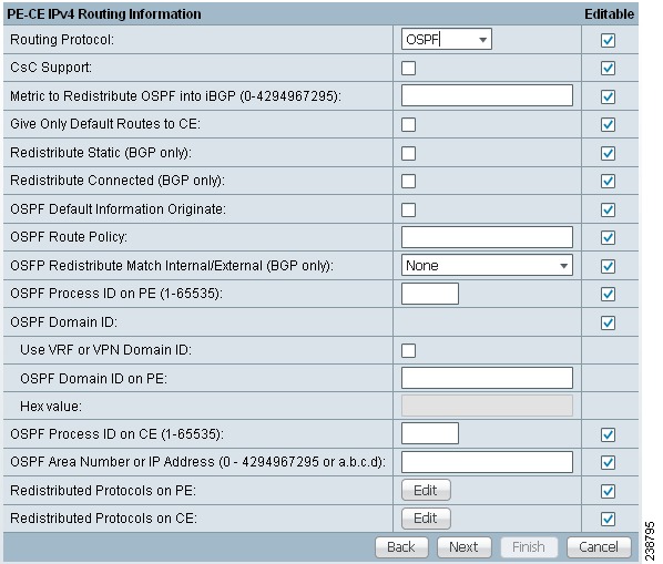
Step 2 ![]() CSC Support: To define a Service Policy with Carrier Supporting Carrier (CSC), choose the CSC Support check box from the MPLS Policy Editor - Routing Information.
CSC Support: To define a Service Policy with Carrier Supporting Carrier (CSC), choose the CSC Support check box from the MPLS Policy Editor - Routing Information.
When CSC Support is checked, the CSC functionality is enabled to the MPLS VPN service. Provisioning CSC is explained in Chapter 30, "Provisioning Carrier Supporting Carrier."
Step 3 ![]() Give Only Default Routes to CE: Specify whether you want to give only the default routes to the CE.
Give Only Default Routes to CE: Specify whether you want to give only the default routes to the CE.
When you enable the Give only default routes to CE option, you indicate whether the site needs full routing or default routing. Full routing is when the site must know specifically which other routes are present in the VPN. Default routing is when it is sufficient to send all packets that are not specifically for your site to the VPN.
If you choose this option, Prime Fulfillment configures the default-info originate command on the PE router under the running protocol RIP or EIGRP and the default-info originate always command on the PE router under the running protocol OSPF for Static and configures an ip route 0.0.0.0 0.0.0.0 <out-going interface name> command on the CE router.
Step 4 ![]() Redistribute Static (BGP only): Indicate whether you want to redistribute static routes into OSPF.
Redistribute Static (BGP only): Indicate whether you want to redistribute static routes into OSPF.
If you are importing static routes into OSPF, check this check box.
Step 5 ![]() Redistribute Connected Routes (BGP only): Indicate whether you want to redistribute the directly connected routes into OSPF.
Redistribute Connected Routes (BGP only): Indicate whether you want to redistribute the directly connected routes into OSPF.
Enabling the Redistribute Connected option imports all the routes to the interfaces connected to the current router. Use the Redistribute Connected option when you want to advertise a network, but you don't want to send routing updates into that network. Note that redistributing connected routes indiscriminately redistributes all connected routes into the routing domain.
This option is meant for iBGP if the routing protocol between PE-CE is a non-BGP protocol. For example, if the routing protocol is RIP, OSPF, EIGRP, or Static, the option is meant for the router bgp that is configured on the PE for the MPLS core. On the PE router, there is one router bgp process running at all times for MPLS. This option is also for BGP.
Step 6 ![]() Default Information Originate: Indicate if you want to generate a default external route into an OSPF routing domain.
Default Information Originate: Indicate if you want to generate a default external route into an OSPF routing domain.
By checking the Default Information Originate check box, other options dynamically appear in the GUI.
a. ![]() Check OSPF Default Information Originate Always to advertise the default route regardless of whether the routing table has a default route.
Check OSPF Default Information Originate Always to advertise the default route regardless of whether the routing table has a default route.
b. ![]() For Metric Value, enter an OSPF metric to be used for generating the default route. Range is 1-16777214.
For Metric Value, enter an OSPF metric to be used for generating the default route. Range is 1-16777214.
c. ![]() For Metric Type, choose one of the following from the drop-down list to specify the link type associated with the default route:
For Metric Type, choose one of the following from the drop-down list to specify the link type associated with the default route:
–![]() None
None
–![]() Type-1 External Route
Type-1 External Route
–![]() Type-2 External Route
Type-2 External Route
d. ![]() For Default Info Route Policy, enter the name of a route policy.
For Default Info Route Policy, enter the name of a route policy.
Usage notes:
•![]() Default Information Originate is available in MPLS policy and service request workflows.
Default Information Originate is available in MPLS policy and service request workflows.
•![]() All suboptions are optional.
All suboptions are optional.
•![]() The route policy, if specified, must be pre-existing on the device. If not, an error is generated when a service request is created based on the policy using this feature.
The route policy, if specified, must be pre-existing on the device. If not, an error is generated when a service request is created based on the policy using this feature.
•![]() This feature is only supported for IOS XR devices.
This feature is only supported for IOS XR devices.
•![]() This feature is only available for IPv4 address family.
This feature is only available for IPv4 address family.
•![]() The following Prime Fulfillment template variables support this feature:
The following Prime Fulfillment template variables support this feature:
–![]() PE_CE_OSPF_ METRIC_VALUE
PE_CE_OSPF_ METRIC_VALUE
–![]() PE_CE_OSPF_METRIC_TYPE
PE_CE_OSPF_METRIC_TYPE
–![]() PE_CE_OSPF_ROUTE_POLICY
PE_CE_OSPF_ROUTE_POLICY
•![]() For sample configlets showing the use of the Default Information Originate option, see Chapter 33, "L3 MPLS VPN (OSPF, Default Information Originate, IOS XR)".
For sample configlets showing the use of the Default Information Originate option, see Chapter 33, "L3 MPLS VPN (OSPF, Default Information Originate, IOS XR)".
Step 7 ![]() OSPF Route Policy: Enter a route policy.
OSPF Route Policy: Enter a route policy.
Usage notes:
•![]() This is an optional attribute.
This is an optional attribute.
•![]() This attribute is only supported with IPv4 routing on IOS and IOS XR PE devices.
This attribute is only supported with IPv4 routing on IOS and IOS XR PE devices.
•![]() This attribute is used to support redistribution of an OSPF route policy. It provides a means to take values from the GUI and insert them into a device configuration, as shown in the examples below.
This attribute is used to support redistribution of an OSPF route policy. It provides a means to take values from the GUI and insert them into a device configuration, as shown in the examples below.
•![]() Example IOS XR configuration following deployment of a service request based on a policy using this attribute:
Example IOS XR configuration following deployment of a service request based on a policy using this attribute:
vrf edn
rd 11.31.128.80:300
address-family ipv4 unicast
redistribute connected
redistribute ospf 3000 route-policy 'xxxx'
•![]() Example IOS configuration:
Example IOS configuration:
address-family ipv4 vrf edn
redistribute connected
redistribute ospf 3000 route-map <route-map>
•![]() Characters are taken from the GUI as is. No validation is performed.
Characters are taken from the GUI as is. No validation is performed.
•![]() If no valid route policy is supplied, the default route policy is used.
If no valid route policy is supplied, the default route policy is used.
•![]() The actual route policy must be configured externally on the device prior to creating a service request based on this policy.
The actual route policy must be configured externally on the device prior to creating a service request based on this policy.
•![]() The following Prime Fulfillment template variables support the redistribution of the OSPF route policy:
The following Prime Fulfillment template variables support the redistribution of the OSPF route policy:
–![]() PE_CE_Ospf_Route_Policy
PE_CE_Ospf_Route_Policy
–![]() PE_MVRFCE_Ospf_ Route_Policy
PE_MVRFCE_Ospf_ Route_Policy
Step 8 ![]() OSPF Redistribute Match Internal/External (BGP only): To set the match criteria by which OSPF routes are redistributed into other routing domains, choose one of the following from the drop-down list:
OSPF Redistribute Match Internal/External (BGP only): To set the match criteria by which OSPF routes are redistributed into other routing domains, choose one of the following from the drop-down list:
•![]() None—Do not specify match criteria for route redistribution. This is the default.
None—Do not specify match criteria for route redistribution. This is the default.
•![]() Internal only—Match routes that are internal to the autonomous system (AS).
Internal only—Match routes that are internal to the autonomous system (AS).
•![]() External only—Match routes that are external to the AS.
External only—Match routes that are external to the AS.
•![]() Both—Match routes that are internal and external to the AS.
Both—Match routes that are internal and external to the AS.
Usage notes:
•![]() This attribute is only supported with IPv4 routing on IOS and IOS XR PE devices.
This attribute is only supported with IPv4 routing on IOS and IOS XR PE devices.
•![]() Example IOS XR configuration for redistribute OSPF match internal:
Example IOS XR configuration for redistribute OSPF match internal:
vrf edn
rd 11.31.128.80:300
address-family ipv4 unicast
redistribute connected
redistribute ospf 3000 match internal
•![]() Example IOS configuration for redistribute OSPF match internal:
Example IOS configuration for redistribute OSPF match internal:
address-family ipv4 vrf edn
redistribute connected
redistribute ospf 3000 match internal
•![]() Example IOS XR configuration for redistribute OSPF match external:
Example IOS XR configuration for redistribute OSPF match external:
vrf edn
rd 11.31.128.80:300
address-family ipv4 unicast
redistribute connected
redistribute ospf 3000 match external
•![]() Example IOS configuration for redistribute OSPF match external:
Example IOS configuration for redistribute OSPF match external:
address-family ipv4 vrf edn
redistribute connected
redistribute ospf 3000 match external 1 external 2
•![]() Example IOS XR configuration when Both option is chosen:
Example IOS XR configuration when Both option is chosen:
redistribute ospf 3000 match internal external
•![]() Example IOS configuration when Both option is chosen:
Example IOS configuration when Both option is chosen:
redistribute ospf 3000 match internal external 1 external 2
•![]() There is no support for external type 1 or external type 2 in the IOS XR variation of this command, but the support exists in IOS. In the Prime Fulfillment GUI, there is no option to specify external type 1 or external type 2. The only option is External only. The generated configlets will differ based on whether the device is IOS or IOS XR.
There is no support for external type 1 or external type 2 in the IOS XR variation of this command, but the support exists in IOS. In the Prime Fulfillment GUI, there is no option to specify external type 1 or external type 2. The only option is External only. The generated configlets will differ based on whether the device is IOS or IOS XR.
•![]() The Prime Fulfillment template variable PE_CE_Ospf_Match_Internal_External support this attribute.
The Prime Fulfillment template variable PE_CE_Ospf_Match_Internal_External support this attribute.
Step 9 ![]() OSPF Process ID on PE: Enter the OSPF process ID for the PE.
OSPF Process ID on PE: Enter the OSPF process ID for the PE.
The OSPF process ID is a unique value assigned for each OSPF routing process within a single router—this process ID is internal to the PE only. You can enter this number either as any decimal number from 1 to 65535, or a number in dotted decimal notation.
Note ![]() For additional information on how the OSPF process ID is handled in Prime Fulfillment, see OSPF Process ID for the IGP (IOS XR Only).
For additional information on how the OSPF process ID is handled in Prime Fulfillment, see OSPF Process ID for the IGP (IOS XR Only).
Step 10 ![]() Use VRF or VPN Domain ID: Check this check box to use an OSPF domain ID from a VRF or VPN.
Use VRF or VPN Domain ID: Check this check box to use an OSPF domain ID from a VRF or VPN.
Usage notes:
•![]() If you do not check this check box, you can enter a value for the OSPF domain ID on the PE in the text field of the OSPF Domain ID on PE attribute (the next attribute in the GUI).
If you do not check this check box, you can enter a value for the OSPF domain ID on the PE in the text field of the OSPF Domain ID on PE attribute (the next attribute in the GUI).
•![]() When you check the Use VPN or VRF Domain ID check box, the fields in the OSPF Domain ID on PE attribute are disabled.
When you check the Use VPN or VRF Domain ID check box, the fields in the OSPF Domain ID on PE attribute are disabled.
•![]() The OSPF domain ID feature is supported only for PE-CE and PE- NoCE policies. The OSPF Domain ID and OSPF Domain ID on PE attributes only show up in the GUI if the policy type is PE-CE or PE-NoCE.
The OSPF domain ID feature is supported only for PE-CE and PE- NoCE policies. The OSPF Domain ID and OSPF Domain ID on PE attributes only show up in the GUI if the policy type is PE-CE or PE-NoCE.
•![]() The OSPF domain ID feature is not supported for MultiVRF-CE policies.
The OSPF domain ID feature is not supported for MultiVRF-CE policies.
•![]() OSPF domain ID is supported only on IOS XR devices. In the case of IOS devices, Prime Fulfillment ignores the this attribute if you use a VRF object or VPN with an OSPF domain ID specified.
OSPF domain ID is supported only on IOS XR devices. In the case of IOS devices, Prime Fulfillment ignores the this attribute if you use a VRF object or VPN with an OSPF domain ID specified.
•![]() The OSPF domain ID attribute uniquely identifies the OSPF domain from which a route is redistributed. This domain ID should be unique per customer. For IOS devices, because IOS allows only one VRF per process, the default behavior is that the OSPF process ID is considered as the OSPF domain ID. IOS XR supports multiple VRFs per process. Therefore, for IOS XR devices, you need to explicitly configure a unique OSPF domain ID for each VRF. You can configure one VRF per OSPF process, but it is not a scalable solution.
The OSPF domain ID attribute uniquely identifies the OSPF domain from which a route is redistributed. This domain ID should be unique per customer. For IOS devices, because IOS allows only one VRF per process, the default behavior is that the OSPF process ID is considered as the OSPF domain ID. IOS XR supports multiple VRFs per process. Therefore, for IOS XR devices, you need to explicitly configure a unique OSPF domain ID for each VRF. You can configure one VRF per OSPF process, but it is not a scalable solution.
•![]() Only OSPF domain ID configuration of type 0005 is supported.
Only OSPF domain ID configuration of type 0005 is supported.
•![]() Note the following points in the case of a service request created based on the policy:
Note the following points in the case of a service request created based on the policy:
–![]() OSPF domain ID configuration is optional. When Use VPN or VRF Domain ID is not enabled and no value is supplied in the OSPF Domain ID field, Prime Fulfillment ignores the OSPF domain ID configuration.
OSPF domain ID configuration is optional. When Use VPN or VRF Domain ID is not enabled and no value is supplied in the OSPF Domain ID field, Prime Fulfillment ignores the OSPF domain ID configuration.
–![]() If Use VPN or VRF Domain ID is enabled, at the time of provisioning Prime Fulfillment gets the OSPF domain ID from the selected VPN object. If an OSPF domain ID is not configured in the VPN object, Prime Fulfillment ignores the OSPF domain ID configuration. No error message is generated.
If Use VPN or VRF Domain ID is enabled, at the time of provisioning Prime Fulfillment gets the OSPF domain ID from the selected VPN object. If an OSPF domain ID is not configured in the VPN object, Prime Fulfillment ignores the OSPF domain ID configuration. No error message is generated.
–![]() When Use VPN or VRF Domain ID is enabled and multiple VPNs are joined for the link (extranet), Prime Fulfillment ignores the OSPF domain configuration.
When Use VPN or VRF Domain ID is enabled and multiple VPNs are joined for the link (extranet), Prime Fulfillment ignores the OSPF domain configuration.
Step 11 ![]() OSPF Domain ID on PE: Enter an OSPF domain ID in decimal format.
OSPF Domain ID on PE: Enter an OSPF domain ID in decimal format.
Usage notes:
•![]() This field is disabled if the Use VPN or VRF Domain ID check box is checked. See notes in the previous step.
This field is disabled if the Use VPN or VRF Domain ID check box is checked. See notes in the previous step.
•![]() Enter the value in decimal format. The Hex value: field is a non-editable text field that displays the equivalent hex value. The hex value is what actually gets displayed on the device.
Enter the value in decimal format. The Hex value: field is a non-editable text field that displays the equivalent hex value. The hex value is what actually gets displayed on the device.
•![]() OSPF domain ID is supported only on IOS XR devices. In the case of IOS devices, Prime Fulfillment ignores the this attribute if you use a VRF object or VPN with an OSPF domain ID specified.
OSPF domain ID is supported only on IOS XR devices. In the case of IOS devices, Prime Fulfillment ignores the this attribute if you use a VRF object or VPN with an OSPF domain ID specified.
Step 12 ![]() OSPF Process ID on CE: Enter the OSPF process ID for the CE.
OSPF Process ID on CE: Enter the OSPF process ID for the CE.
The OSPF process ID is a unique value assigned for each OSPF routing process within a single router—this process ID is internal to the CE only. You can enter this number either as any decimal number from 1 to 65535, or a number in dotted decimal notation.
Note ![]() For additional information on how the OSPF process ID is handled in Prime Fulfillment, see OSPF Process ID for the IGP (IOS XR Only).
For additional information on how the OSPF process ID is handled in Prime Fulfillment, see OSPF Process ID for the IGP (IOS XR Only).
Step 13 ![]() OSPF Process Area Number: Enter the OSPF process area number.
OSPF Process Area Number: Enter the OSPF process area number.
You can enter the OSPF area number for the PE either as any decimal number in the range specified, or a number in dotted decimal notation.
Step 14 ![]() Redistributed Protocols on PE: If necessary, specify the redistributed protocols into the PE.
Redistributed Protocols on PE: If necessary, specify the redistributed protocols into the PE.
Note ![]() Restricting the amount of redistribution can be important in an OSPF environment. Whenever a route is redistributed into OSPF, it is done so as an external OSPF route. The OSPF protocol floods external routes across the OSPF domain, which increases the protocol's overhead and the CPU load on all the routers participating in the OSPF domain.
Restricting the amount of redistribution can be important in an OSPF environment. Whenever a route is redistributed into OSPF, it is done so as an external OSPF route. The OSPF protocol floods external routes across the OSPF domain, which increases the protocol's overhead and the CPU load on all the routers participating in the OSPF domain.
To specify the protocols that OSPF needs to import to the PE, follow these steps.
a. ![]() From the Redistribute Protocols on PE option, click Edit.
From the Redistribute Protocols on PE option, click Edit.
The PE Redistributed Protocol dialog box appears.
b. ![]() Click Add.
Click Add.
The PE Redistributed Protocols dialog box appears.
c. ![]() From the Protocol Type drop-down list, choose the protocol you want to import into the PE.
From the Protocol Type drop-down list, choose the protocol you want to import into the PE.
You can choose one of the following: Static, EIGRP, or RIP.
•![]() Redistribute Static. When you choose Static routes for redistribution into OSPF, Prime Fulfillment imports the static routes into the PE that is running OSPF.
Redistribute Static. When you choose Static routes for redistribution into OSPF, Prime Fulfillment imports the static routes into the PE that is running OSPF.
There are no parameters or metrics required for redistributing Static routes into the PE.
•![]() Redistribute EIGRP (Enhanced IGRP). When you choose the EIGRP protocol for redistribution into OSPF, Prime Fulfillment imports the EIGRP routes into the PE that is running OSPF.
Redistribute EIGRP (Enhanced IGRP). When you choose the EIGRP protocol for redistribution into OSPF, Prime Fulfillment imports the EIGRP routes into the PE that is running OSPF.
Parameter: EIGRP autonomous system (AS) number
Metric: Any numeral from 1 to 16777214
•![]() Redistribute RIP. When you choose the RIP protocol for redistribution into OSPF, Prime Fulfillment imports the RIP routes into the PE that is running OSPF.
Redistribute RIP. When you choose the RIP protocol for redistribution into OSPF, Prime Fulfillment imports the RIP routes into the PE that is running OSPF.
Parameter: No parameter required.
Metric: Any numeral from 1 to 16777214.
d. ![]() Choose the protocol you want to redistribute into OSPF on the PE.
Choose the protocol you want to redistribute into OSPF on the PE.
e. ![]() Enter the appropriate parameter for the protocol selected.
Enter the appropriate parameter for the protocol selected.
f. ![]() Click Add.
Click Add.
g. ![]() Repeat these steps for any additional protocols you want to redistribute into OSPF on the PE, then click OK.
Repeat these steps for any additional protocols you want to redistribute into OSPF on the PE, then click OK.
Step 15 ![]() Specify whether you want to redistribute the routing protocols into the CE.
Specify whether you want to redistribute the routing protocols into the CE.
Redistribute Protocols on CE: To specify the protocols that OSPF needs to import routing information to the CE, follow these steps.
a. ![]() From the Redistribute Protocols on CE option, click Edit.
From the Redistribute Protocols on CE option, click Edit.
The CE Redistributed Protocol dialog box appears.
b. ![]() Click Add.
Click Add.
The CE Redistributed Protocols dialog box appears.
c. ![]() From the Protocol Type drop-down list, choose the protocol you want to import into the CE.
From the Protocol Type drop-down list, choose the protocol you want to import into the CE.
You can choose one of the following protocols: Static, RIP, BGP, Connected (routes), IGRP, EIGRP, or IS-IS.
•![]() Redistribute Static. When you choose Static routes for redistribution into OSPF, Prime Fulfillment imports the static routes into the CE that is running OSPF.
Redistribute Static. When you choose Static routes for redistribution into OSPF, Prime Fulfillment imports the static routes into the CE that is running OSPF.
There are no parameters required for redistributing Static routes into the CE.
•![]() Redistribute RIP. When you choose the RIP protocol for redistribution into OSPF, Prime Fulfillment imports the RIP routes into the CE that is running OSPF.
Redistribute RIP. When you choose the RIP protocol for redistribution into OSPF, Prime Fulfillment imports the RIP routes into the CE that is running OSPF.
Parameter: No parameter required
•![]() Redistribute BGP (Border Gateway Protocol). When you choose the BGP protocol for redistribution into OSPF, Prime Fulfillment imports the BGP routes into the CE that is running OSPF.
Redistribute BGP (Border Gateway Protocol). When you choose the BGP protocol for redistribution into OSPF, Prime Fulfillment imports the BGP routes into the CE that is running OSPF.
Parameter: BGP autonomous system (AS) number
•![]() Redistribute Connected routes. When you choose the Connected routes for redistribution into OSPF, Prime Fulfillment imports all the routes to the interfaces connected to the current router. Use the Connected option when you want to advertise a network, but you don't want to send routing updates into that network. Note that redistributing connected routes indiscriminately redistributes all connected routes into the routing domain.
Redistribute Connected routes. When you choose the Connected routes for redistribution into OSPF, Prime Fulfillment imports all the routes to the interfaces connected to the current router. Use the Connected option when you want to advertise a network, but you don't want to send routing updates into that network. Note that redistributing connected routes indiscriminately redistributes all connected routes into the routing domain.
Parameter: No parameter required
•![]() Redistribute IGRP (Interior Gateway Routing Protocol). When you choose the IGRP (Interior Gateway Routing) protocol for redistribution into OSPF, IP Solution Center imports the IGRP routes into the CE that is running OSPF.
Redistribute IGRP (Interior Gateway Routing Protocol). When you choose the IGRP (Interior Gateway Routing) protocol for redistribution into OSPF, IP Solution Center imports the IGRP routes into the CE that is running OSPF.
Parameter: IGRP autonomous system (AS) number
•![]() Redistribute EIGRP (Enhanced IGRP). When you choose the EIGRP protocol for redistribution into OSPF, Prime Fulfillment imports the EIGRP routes into the CE that is running OSPF.
Redistribute EIGRP (Enhanced IGRP). When you choose the EIGRP protocol for redistribution into OSPF, Prime Fulfillment imports the EIGRP routes into the CE that is running OSPF.
Parameter: EIGRP autonomous system (AS) number
•![]() Redistribute IS-IS (Intermediate System-to-Intermediate System). When you choose the IS-IS protocol for redistribution into OSPF, Prime Fulfillment imports the IS-IS routes into the CE that is running OSPF.
Redistribute IS-IS (Intermediate System-to-Intermediate System). When you choose the IS-IS protocol for redistribution into OSPF, Prime Fulfillment imports the IS-IS routes into the CE that is running OSPF.
Parameter: IS-IS tag number
d. ![]() Choose the protocol you want to redistribute into OSPF on the CE.
Choose the protocol you want to redistribute into OSPF on the CE.
e. ![]() Enter the appropriate parameter for the selected protocol.
Enter the appropriate parameter for the selected protocol.
f. ![]() Click Add.
Click Add.
g. ![]() Repeat these steps for any additional protocols you want to redistribute into OSPF on the CE, then click OK.
Repeat these steps for any additional protocols you want to redistribute into OSPF on the CE, then click OK.
Step 16 ![]() When you are satisfied with the OSPF protocol settings for this service policy, click Next.
When you are satisfied with the OSPF protocol settings for this service policy, click Next.
The MPLS Policy VRF and VPN Membership dialog box appears. To proceed, see Defining VRF and VPN Information.
OSPF Process ID for the IGP (IOS XR Only)
Note ![]() The information in this section only applies to IOS XR devices, since IOS XR supports a virtual OSPF process. It is not applicable to IOS devices.
The information in this section only applies to IOS XR devices, since IOS XR supports a virtual OSPF process. It is not applicable to IOS devices.
For IOS XR devices, Prime Fulfillment keeps the OSPF process for the Interior Gateway Protocol (IGP) as a separate process. By default, the OSPF for all PE-CE links is another process. For further OSPF processes, the PE-CE VRFs are under that parent.
The user is responsible for determining and tracking the OSPF process ID. Prime Fulfillment checks that the PE-CE process ID is different from the IGP process ID and provides a warning message if the process ID is already in use.
If the user provides an OSPF process ID that is already in use for IGP purposes, Prime Fulfillment generates a warning message during deployment of the service request. An OSPF process is considered to be in use if it references a VRF. If it does so, then it is regarded as a non-IGP process; otherwise, it is regarded as an IGP process.
Prime Fulfillment provides a DCPL property to set the maximum number of OSPF processes. The DCPL property is Provisioning\Service\mpls\ospfProcessLimit. The default for this value is 2. Prime Fulfillment keeps track of how many OSPF processes have been configured. If the limit is exceeded or reached, a warning message is generated during the deployment of the service request. Aside from the warning message, there are no side effects from exceeding the limit.
Note ![]() The DCPL limit represents the total of all OSPF processes (IGP or otherwise). No warning is generated if the OSPF process ID is already present as an VRF-based OSPF process. A warning is generated if there is more than one VRF-based OSPF process (assuming a default value of 2 for ospfProcessLimit).
The DCPL limit represents the total of all OSPF processes (IGP or otherwise). No warning is generated if the OSPF process ID is already present as an VRF-based OSPF process. A warning is generated if there is more than one VRF-based OSPF process (assuming a default value of 2 for ospfProcessLimit).
See the following configuration examples.
Example: Core IGP (90)
router ospf 90
nsr
log adjacency changes
router-id 11.31.128.77
bfd minimum-interval 200
bfd multiplier 3
network point-to-point
nsf cisco
auto-cost reference-bandwidth 100000
redistribute rip metric 3 metric-type 1
redistribute isis ntt metric 10 metric-type 1
address-family ipv4 unicast
area 51
mpls traffic-eng
interface Loopback0
!
interface GigabitEthernet0/0/0/0
network broadcast
!
!
area 0.0.0.0
mpls traffic-eng
interface GigabitEthernet0/0/0/1
!
interface GigabitEthernet0/0/0/2
network point-to-point
!
interface GigabitEthernet0/0/0/4
network point-to-point
!
interface TenGigE0/3/0/0
!
!
mpls traffic-eng router-id Loopback0
mpls traffic-eng multicast-intact
Example: PE-CE VRFs (3000)
router ospf 3000
vrf edn
log adjacency changes detail
router-id 1.1.1.77
domain-tag 77
area 0.0.0.100
bfd minimum-interval 250
bfd fast-detect
bfd multiplier 3
network point-to-point
stub
interface GigabitEthernet0/0/5/7.101
!
!
!
vrf regus
log adjacency changes detail
router-id 2.2.2.1
domain-tag 3177
network point-to-point
address-family ipv4 unicast
area 51
bfd minimum-interval 250
bfd fast-detect
bfd multiplier 3
network point-to-point
interface Loopback9000
Note ![]() If route-policy is used on the router, matching is not applicable.
If route-policy is used on the router, matching is not applicable.
EIGRP Protocol Chosen
Enhanced IGRP (EIGRP) is a hybrid routing protocol that discovers a network like a distance vector protocol (namely IGRP), but maintains a topological database for rapid reconvergence. EIGRP supports variable length subnet masks and discontinuous subnets. When configured for IP, it automatically redistributes routes with IGRP processes defined in the same autonomous system. By default, EIGRP autosummarizes subnets at the classful network boundaries.
EIGRP performs the same metric accumulation as IGRP. However, if you examine the metric calculation between IGRP and EIGRP, you will see that the EIGRP value is much greater. If you divide the EIGRP metric by 256, you get the same IGRP metric value.
EIGRP allows all routers involved in a topology change to synchronize at the same time. Routers that are not affected by topology changes are not involved in the recomputation. The result is very fast convergence time.
To specify EIGRP as the routing protocol for the service policy, perform the following steps.
Step 1 ![]() Choose EIGRP from the Routing Protocol drop-down list.
Choose EIGRP from the Routing Protocol drop-down list.
The EIGRP Routing Protocol dialog box appears, as shown in Figure 24-8.
Figure 24-8 EIGRP Selected as the Routing Protocol
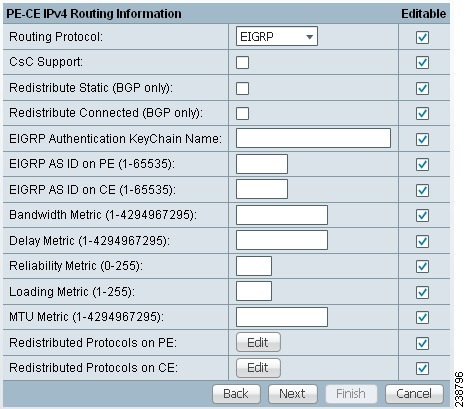
Step 2 ![]() CSC Support: To define a Service Policy with Carrier Supporting Carrier (CSC), choose the CSC Support check box from the MPLS Policy Editor - Routing Information.
CSC Support: To define a Service Policy with Carrier Supporting Carrier (CSC), choose the CSC Support check box from the MPLS Policy Editor - Routing Information.
When CSC Support is checked, the CSC functionality is enabled to the MPLS VPN service. Provisioning CSC is explained in Chapter 30, "Provisioning Carrier Supporting Carrier."
This attribute is not available if the IP addressing scheme was set to IPv6 in previous steps.
Step 3 ![]() Redistribute Static: (BGP only) If appropriate, enable the Redistribute Static (BGP only) option.
Redistribute Static: (BGP only) If appropriate, enable the Redistribute Static (BGP only) option.
When you enable the Redistribute Static option for BGP, the software imports the static routes into the core network (running BGP).
Step 4 ![]() Redistribute Connected: (BGP only) If appropriate, enable the Redistribute Connected (BGP only) option.
Redistribute Connected: (BGP only) If appropriate, enable the Redistribute Connected (BGP only) option.
When you enable the Redistribute Connected option, the connected routes (that is, the routes to the directly connected PEs or CEs) are distributed to all the other CEs in that particular VPN. This option is meant for iBGP if the routing protocol between PE-CE is a non-BGP protocol. For example, if the routing protocol is RIP, OSPF, EIGRP, or Static, the option is meant for the router BGP that is configured on the PE for the MPLS core. On the PE router, there is one router PCP process running at all times for MPLS. This option is also for BGP.
Note ![]() Redistributing connected routes can be problematic because all the connected routes are redistributed indiscriminately into a specified routing domain. If you do not want all connected routes to be redistributed, use a distribute-list out statement to identify the specific connected routes that should be redistributed.
Redistributing connected routes can be problematic because all the connected routes are redistributed indiscriminately into a specified routing domain. If you do not want all connected routes to be redistributed, use a distribute-list out statement to identify the specific connected routes that should be redistributed.
Step 5 ![]() EIGRP Authentication KeyChain Name: Enter a keychain name to authenticate all EIGRP protocol traffic on one or more interfaces.
EIGRP Authentication KeyChain Name: Enter a keychain name to authenticate all EIGRP protocol traffic on one or more interfaces.
Usage notes:
•![]() No space characters and backslash (\) characters are allowed in the keychain name.
No space characters and backslash (\) characters are allowed in the keychain name.
•![]() If no name is specified, EIGRP keychain authentication is not deployed.
If no name is specified, EIGRP keychain authentication is not deployed.
•![]() This option is supported for both IPv4 and IPv6 address families.
This option is supported for both IPv4 and IPv6 address families.
•![]() This option is available only for IOS XR devices.
This option is available only for IOS XR devices.
•![]() For sample configlets showing the use of the EIGRP Authentication KeyChain Name option, see
For sample configlets showing the use of the EIGRP Authentication KeyChain Name option, see
Chapter 33, "PE L3 MPLS VPN (EIGRP, Authentication Keychain Name, IOS XR)".
Step 6 ![]() EIGRP AS ID on PE: Enter the EIGRP autonomous system ID on the PE.
EIGRP AS ID on PE: Enter the EIGRP autonomous system ID on the PE.
This is a unique 16-bit number.
Step 7 ![]() EIGRP AS ID on CE: Enter the EIGRP autonomous system ID on the CE.
EIGRP AS ID on CE: Enter the EIGRP autonomous system ID on the CE.
This is a unique 16-bit number.
Step 8 ![]() Enter the values for the EIGRP metrics as described below.
Enter the values for the EIGRP metrics as described below.
EIGRP Metrics
EIGRP uses metrics in the same way as IGRP. Each route in the route table has an associated metric. EIGRP uses a composite metric much like IGRP, except that it is modified by a multiplier of 256. Bandwidth, Delay, Load, Reliability, and MTU are the submetrics. Like IGRP, EIGRP chooses a route based primarily on bandwidth and delay, or the composite metric with the lowest numerical value. When EIGRP calculates this metric for a route, it calls it the feasible distance to the route. EIGRP calculates a feasible distance to all routes in the network.
Bandwidth Metric: Bandwidth is expressed in units of Kilobits. It must be statically configured to accurately represent the interfaces that EIGRP is running on. For example, the default bandwidth of a 56-kbps interface and a T1 interface is 1,544 kbps.
Delay Metric: Delay is expressed in microseconds. It, too, must be statically configured to accurately represent the interface that EIGRP is running on. The delay on an interface can be adjusted with the delay time_in_microseconds interface subcommand.
Reliability Metric: Reliability is a dynamic number in the range of 1 to 255, where 255 is a 100 percent reliable link and 1 is an unreliable link.
Loading Metric: Load is the number in the range of 1 to 255 that shows the output load of an interface. This value is dynamic and can be viewed using the show interfaces command. A value of 1 indicates a minimally loaded link, whereas 255 indicates a link loaded 100 percent.
MTU Metric: The maximum transmission unit (MTU) is the recorded smallest MTU value in the path, usually 1500.
Note ![]() Whenever you are influencing routing decisions in IGRP or EIGRP, use the Delay metric over Bandwidth. Changing bandwidth can affect other routing protocols, such as OSPF. Changing delay affects only IGRP and EIGRP.
Whenever you are influencing routing decisions in IGRP or EIGRP, use the Delay metric over Bandwidth. Changing bandwidth can affect other routing protocols, such as OSPF. Changing delay affects only IGRP and EIGRP.
Step 9 ![]() Redistributed Protocols on PE: If necessary, specify the redistributed protocols on the PE.
Redistributed Protocols on PE: If necessary, specify the redistributed protocols on the PE.
When configured for IP, it automatically redistributes routes with IGRP processes defined in the same autonomous system. By default, EIGRP autosummarizes subnets at the classful network boundaries.
To specify the protocols that EIGRP needs to import to the PE:
a. ![]() From the Redistribute Protocols on PE option, click Edit.
From the Redistribute Protocols on PE option, click Edit.
The PE Redistributed Protocol dialog box appears.
b. ![]() Click Add.
Click Add.
The PE Redistributed Protocols dialog box appears.
c. ![]() From the Protocol Type drop-down list, choose the protocol you want to import into the PE.
From the Protocol Type drop-down list, choose the protocol you want to import into the PE.
You can choose one of the following: Static, RIP, or OSPF.
•![]() Redistribute Static. When you choose Static routes for redistribution into EIGRP, Prime Fulfillment imports the static routes into the PE that is running OSPF.
Redistribute Static. When you choose Static routes for redistribution into EIGRP, Prime Fulfillment imports the static routes into the PE that is running OSPF.
There are no parameters or metrics required for redistributing Static routes into the PE.
•![]() Redistribute RIP. When you choose the RIP protocol for redistribution into EIGRP, Prime Fulfillment imports the RIP routes into the PE that is running EIGRP.
Redistribute RIP. When you choose the RIP protocol for redistribution into EIGRP, Prime Fulfillment imports the RIP routes into the PE that is running EIGRP.
Parameter: No parameter required
Metric: Any numeral from 1 to 16777214
•![]() Redistribute OSPF (Open Shortest Path First). When you choose the OSPF protocol for redistribution into EIGRP, Prime Fulfillment imports the OSPF routes into the PE that is running EIGRP.
Redistribute OSPF (Open Shortest Path First). When you choose the OSPF protocol for redistribution into EIGRP, Prime Fulfillment imports the OSPF routes into the PE that is running EIGRP.
Parameter: OSPF process number
Metric: Any numeral from 1 to 16
d. ![]() Choose the protocol you want to redistribute into EIGRP on the CE.
Choose the protocol you want to redistribute into EIGRP on the CE.
e. ![]() Enter the appropriate parameter for the protocol selected.
Enter the appropriate parameter for the protocol selected.
f. ![]() Click Add.
Click Add.
g. ![]() Repeat these steps for any additional protocols you want to redistribute into EIGRP on the PE, then click OK.
Repeat these steps for any additional protocols you want to redistribute into EIGRP on the PE, then click OK.
Step 10 ![]() Redistribute Protocols on CE: Specify whether you want to redistribute the routing protocols into the CE.
Redistribute Protocols on CE: Specify whether you want to redistribute the routing protocols into the CE.
To specify the protocols that EIGRP needs to import routing information to the CE:
a. ![]() From the Redistribute Protocols on CE option, click Edit.
From the Redistribute Protocols on CE option, click Edit.
The CE Redistributed Protocol dialog box appears.
b. ![]() Click Add.
Click Add.
The CE Redistributed Protocols dialog box appears.
c. ![]() From the Protocol Type drop-down list, choose the protocol you want to import into the CE.
From the Protocol Type drop-down list, choose the protocol you want to import into the CE.
You can choose one of the following protocols: Static, BGP, Connected (routes), IGRP, RIP, OSPF, or IS-IS.
•![]() Redistribute Static. When you choose Static routes for redistribution into EIGRP, Prime Fulfillment imports the static routes into the CE that is running OSPF.
Redistribute Static. When you choose Static routes for redistribution into EIGRP, Prime Fulfillment imports the static routes into the CE that is running OSPF.
There are no parameters required for redistributing Static routes into the CE.
•![]() Redistribute BGP (Border Gateway Protocol). When you choose the BGP protocol for redistribution into EIGRP, Prime Fulfillment imports the BGP routes into the CE that is running OSPF.
Redistribute BGP (Border Gateway Protocol). When you choose the BGP protocol for redistribution into EIGRP, Prime Fulfillment imports the BGP routes into the CE that is running OSPF.
Parameter: BGP autonomous system (AS) number
•![]() Redistribute Connected routes. When you choose the Connected routes for redistribution into EIGRP, Prime Fulfillment imports all the routes to the interfaces connected to the current router. Use the Connected option when you want to advertise a network, but you don't want to send routing updates into that network. Note that redistributing connected routes indiscriminately redistributes all connected routes into the routing domain.
Redistribute Connected routes. When you choose the Connected routes for redistribution into EIGRP, Prime Fulfillment imports all the routes to the interfaces connected to the current router. Use the Connected option when you want to advertise a network, but you don't want to send routing updates into that network. Note that redistributing connected routes indiscriminately redistributes all connected routes into the routing domain.
When you enable the Redistribute Connected option, the connected routes (that is, the routes to the directly connected PEs or CEs) are distributed to all the other CEs in that particular VPN. This option is meant for iBGP if the routing protocol between PE-CE is a non-BGP protocol. For example, if the routing protocol is RIP, OSPF, EIGRP, or Static, the option is meant for the router BGP that is configured on the PE for the MPLS core. On the PE router, there is one router BGP process running at all times for MPLS. This option is also for BGP.
Parameter: No parameter required
•![]() Redistribute IGRP (Interior Gateway Routing Protocol). When you choose the IGRP (Interior Gateway Routing) protocol for redistribution into EIGRP, IP Solution Center imports the IGRP routes into the CE that is running EIGRP.
Redistribute IGRP (Interior Gateway Routing Protocol). When you choose the IGRP (Interior Gateway Routing) protocol for redistribution into EIGRP, IP Solution Center imports the IGRP routes into the CE that is running EIGRP.
Parameter: IGRP autonomous system (AS) number
•![]() Redistribute RIP. When you choose the RIP protocol for redistribution into EIGRP, Cisco Prime Fulfillment imports the RIP routes into the CE that is running EIGRP.
Redistribute RIP. When you choose the RIP protocol for redistribution into EIGRP, Cisco Prime Fulfillment imports the RIP routes into the CE that is running EIGRP.
Parameter: No parameter required
•![]() Redistribute OSPF (Open Shortest Path First). When you choose the OSPF protocol for redistribution into EIGRP, Prime Fulfillment imports the OSPF routes into the CE that is running EIGRP.
Redistribute OSPF (Open Shortest Path First). When you choose the OSPF protocol for redistribution into EIGRP, Prime Fulfillment imports the OSPF routes into the CE that is running EIGRP.
Parameter: OSPF process number
•![]() Redistribute IS-IS (Intermediate System-to-Intermediate System). When you choose the IS-IS protocol for redistribution into EIGRP, Prime Fulfillment imports the IS-IS routes into the CE that is running EIGRP.
Redistribute IS-IS (Intermediate System-to-Intermediate System). When you choose the IS-IS protocol for redistribution into EIGRP, Prime Fulfillment imports the IS-IS routes into the CE that is running EIGRP.
Parameter: IS-IS tag number
d. ![]() Choose the protocol you want to redistribute into EIGRP on the CE.
Choose the protocol you want to redistribute into EIGRP on the CE.
e. ![]() Enter the appropriate parameter for the selected protocol.
Enter the appropriate parameter for the selected protocol.
f. ![]() Click Add.
Click Add.
g. ![]() Repeat these steps for any additional protocols you want to redistribute into EIGRP on the CE, then click OK.
Repeat these steps for any additional protocols you want to redistribute into EIGRP on the CE, then click OK.
Step 11 ![]() When you are satisfied with the EIGRP protocol settings for this service policy, click Next.
When you are satisfied with the EIGRP protocol settings for this service policy, click Next.
The MPLS Policy VRF and VPN Membership dialog box appears. To proceed, see Defining VRF and VPN Information.
None Chosen: Cable Services
When operating a cable link, the link does not run a routing protocol. The None option in the service policy routing protocol dialog box is provided to allow for configuring a service over a cable link without having to unnecessarily specify a routing protocol.
If this service policy is for cable services, perform the following steps.
Step 1 ![]() Choose None from the list of routing protocols.
Choose None from the list of routing protocols.
The following dialog box appears, as shown in Figure 24-9.
Figure 24-9 No Routing Protocol Selected
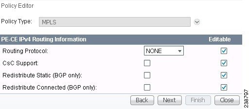
Step 2 ![]() CSC Support: To define a Service Policy with Carrier Supporting Carrier (CSC), choose the CSC Support check box from the MPLS Policy Editor - Routing Information.
CSC Support: To define a Service Policy with Carrier Supporting Carrier (CSC), choose the CSC Support check box from the MPLS Policy Editor - Routing Information.
When CSC Support is checked, the CSC functionality is enabled to the MPLS VPN service. Provisioning CSC is explained in Chapter 30, "Provisioning Carrier Supporting Carrier."
Step 3 ![]() Redistribute Static: If you want to distribute static routes into the provider core network (which runs BGP), check the Redistribute Static (BGP only) check box.
Redistribute Static: If you want to distribute static routes into the provider core network (which runs BGP), check the Redistribute Static (BGP only) check box.
Step 4 ![]() Redistribute Connected: Because there is no routing protocol on the cable link, we recommend that you redistribute the connected routes to all the other CEs in the VPN. To do so, check the Redistribute Connected (BGP only) check box.
Redistribute Connected: Because there is no routing protocol on the cable link, we recommend that you redistribute the connected routes to all the other CEs in the VPN. To do so, check the Redistribute Connected (BGP only) check box.
When you enable the Redistribute Connected option, the connected routes (that is, the routes to the directly connected PEs or CEs) are distributed to all the other CEs in that particular VPN. This option is meant for iBGP if the routing protocol between PE-CE is a non-BGP protocol. For example, if the routing protocol is RIP, OSPF, EIGRP, or Static, the option is meant for the router BGP that is configured on the PE for the MPLS core. On the PE router, there is one router BGP process running at all times for MPLS. This option is also for BGP.
Step 5 ![]() When finished specifying the necessary settings, click Next.
When finished specifying the necessary settings, click Next.
The MPLS Policy VRF and VPN Membership dialog box appears. To proceed, see Defining VRF and VPN Information.
Defining VRF and VPN Information
When you are finished defining the routing protocol(s) for the service policy, you must then specify the VRF and VPN information for this service policy. To do this, perform the following steps.
Step 1 ![]() The MPLS Policy VRF and VPN Membership dialog box appears, as shown in Figure 24-10.
The MPLS Policy VRF and VPN Membership dialog box appears, as shown in Figure 24-10.
Figure 24-10 Specifying the VRF Information
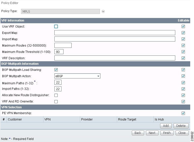
Step 2 ![]() If you want to set the VRF and VPN attributes via a previously defined VRF object, check the Use VRF Object check box.
If you want to set the VRF and VPN attributes via a previously defined VRF object, check the Use VRF Object check box.
For more information on this feature, see Chapter 22, "Independent VRF Management." That chapter describes how to use independent VRF objects in MPLS VPN service policies and service requests.
If you are not using the VRF object feature, then define the VRF and VPN attributes as described in the following steps.
Step 3 ![]() Export Map: If necessary, enter the name of the export route map.
Export Map: If necessary, enter the name of the export route map.
The name of the export route map you enter here must be the name of an existing export route map on the PE.
Note ![]() IOS supports only one export route map per VRF. Therefore, there can be only one export route map per VPN.
IOS supports only one export route map per VRF. Therefore, there can be only one export route map per VPN.
When you use the Prime Fulfillment software to define a management VPN, Prime Fulfillment automatically generates an export route map for the management VPN. Because the Cisco IOS supports only one export route map per VRF and that route map is reserved for the management VPN, the Export Map field is not available if the VRF is part of the management VPN.
An export route map does not apply a filter; it can be used to override the default set of route targets associated with a route.
Step 4 ![]() Import Map: Enter the name of the import route map.
Import Map: Enter the name of the import route map.
The name of the import route map you enter here must be the name of an existing import route map on the PE.
Note ![]() IOS supports only one import route map per VRF. Therefore, there can be only one import route map per VPN.
IOS supports only one import route map per VRF. Therefore, there can be only one import route map per VPN.
An import route map does apply a filter. Therefore, if you want to exclude a particular route from the VRF on this PE, you can either set an export route map on the sending router to make sure it does not have any route targets that can be imported into the current VRF, or create an import route map on the PE to exclude the route.
Step 5 ![]() Maximum Routes: Specify the maximum number of routes that can be imported into the VRF on this PE.
Maximum Routes: Specify the maximum number of routes that can be imported into the VRF on this PE.
Note ![]() Prime Fulfillment will not allow provisioning of another value for Maximum Routes after it is configured with a value. Because a VRF might be used by multiple interfaces (links), after this value is configured for a link, it is recommended that you do not manually change it. Prime Fulfillment generates an error if you try to change the maximum routes value for an existing or new service request using this VRF.
Prime Fulfillment will not allow provisioning of another value for Maximum Routes after it is configured with a value. Because a VRF might be used by multiple interfaces (links), after this value is configured for a link, it is recommended that you do not manually change it. Prime Fulfillment generates an error if you try to change the maximum routes value for an existing or new service request using this VRF.
Step 6 ![]() Maximum Route Threshold: Specify the threshold value for the number of maximum routes.
Maximum Route Threshold: Specify the threshold value for the number of maximum routes.
When the specified number of maximum routes is exceeded, Prime Fulfillment sends a warning message.
Step 7 ![]() VRF Description: Optionally, you can enter a description of the VRF for the current VPN.
VRF Description: Optionally, you can enter a description of the VRF for the current VPN.
Step 8 ![]() BGP Multipath Load Sharing: Check this check box to enable BGP multipath load sharing and maximum path configuration.
BGP Multipath Load Sharing: Check this check box to enable BGP multipath load sharing and maximum path configuration.
See BGP Multipath Load Sharing and Maximum Path Configuration, for details on using this option.
Step 9 ![]() Allocate New Route Distinguisher: A route distinguisher (RD) is a 64-bit number appended to each IPv4 route that ensures that IP addresses that are unique in the VPN are also unique in the MPLS core. This extended address is also referred to as a VPN-IPv4 address.
Allocate New Route Distinguisher: A route distinguisher (RD) is a 64-bit number appended to each IPv4 route that ensures that IP addresses that are unique in the VPN are also unique in the MPLS core. This extended address is also referred to as a VPN-IPv4 address.
When Allocate New Route Distinguisher is enabled, create a new VRF if there is no matching VRF configuration on that PE; otherwise, reuse it.
When Allocate New Route Distinguisher is disabled, find the first matching VRF configuration across the entire range of PEs, regardless of the PE. If this VRF is found on the PE being configured, reuse it. If it is not found on the PE, create it.
Note ![]() The service request might get a VRF that has already been configured on another PE router.
The service request might get a VRF that has already been configured on another PE router.
Prime Fulfillment automatically sets the route target (RT) and RD values, but you can assign your own values by checking the VRF and RD check box instead.
Note ![]() The Allocate New Route Distinguisher option is disabled if you enabled the unique route distinguisher feature when the VPN was created. For information, see Chapter 21, "Enabling a Unique Route Distinguisher for a VPN".
The Allocate New Route Distinguisher option is disabled if you enabled the unique route distinguisher feature when the VPN was created. For information, see Chapter 21, "Enabling a Unique Route Distinguisher for a VPN".
Step 10 ![]() VRF and RD Overwrite: When you enable the VRF and RD Overwrite option, this dialog box presents two new fields, as shown in Figure 24-11, that allow you to overwrite the default VRF name and route distinguisher values.
VRF and RD Overwrite: When you enable the VRF and RD Overwrite option, this dialog box presents two new fields, as shown in Figure 24-11, that allow you to overwrite the default VRF name and route distinguisher values.

Note ![]() The VRF and RD Overwrite option is disabled if you enabled the unique route distinguisher feature when the VPN was created. For information, see Chapter 21, "Enabling a Unique Route Distinguisher for a VPN".
The VRF and RD Overwrite option is disabled if you enabled the unique route distinguisher feature when the VPN was created. For information, see Chapter 21, "Enabling a Unique Route Distinguisher for a VPN".
Figure 24-11 No Routing Protocol Selected a
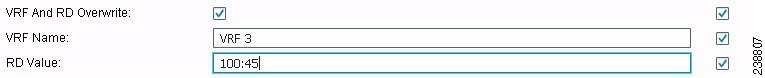
a. ![]() VRF Name: Enter the new VRF name. It is recommended not to use special characters
VRF Name: Enter the new VRF name. It is recommended not to use special characters
(' ` " < > ( ) [ ] { } / \ & ^ ! ? ~ * % = , . + |), as this may cause misconfiguration of the VRF name for certain devices.
b. ![]() RD Value: Enter the new RD value.
RD Value: Enter the new RD value.
Note ![]() In MPLS service requests, once you specify values to sub-attributes under the VRF and RD Overwrite attribute (that is, the VRF Name and RD Value attributes) and save the service request, both of these fields are disabled and are no longer editable. This behavior was introduced because changing the default values for the VRF Name and RD Value can alter or disable currently running service requests. Therefore, if these values need to be changed on a deployed service request, the workaround is that you must decommission and purge the service request and create a new service request. In the case of a new service request that has not yet been deployed, you must force purge the service request and then create a new service with new values.
In MPLS service requests, once you specify values to sub-attributes under the VRF and RD Overwrite attribute (that is, the VRF Name and RD Value attributes) and save the service request, both of these fields are disabled and are no longer editable. This behavior was introduced because changing the default values for the VRF Name and RD Value can alter or disable currently running service requests. Therefore, if these values need to be changed on a deployed service request, the workaround is that you must decommission and purge the service request and create a new service request. In the case of a new service request that has not yet been deployed, you must force purge the service request and then create a new service with new values.
Step 11 ![]() PE VPN Membership: In the check box, specify the VPN associated with this service policy.
PE VPN Membership: In the check box, specify the VPN associated with this service policy.
The PE VPN Membership information includes the customer name, VPN name, service provider name, CE routing community name, and whether the CERC type is a hub-and-spoke CERC or a fully meshed CERC.
If the Is Hub check box is checked, it indicates that the CERC type is hub-and-spoke.
Using the Add and Delete buttons, you can add a VPN to this list or delete a VPN from this list.
Step 12 ![]() If you would like to enable template and data file support for the policy, click the Next button to access the Template Association window, and then see Enabling Template Association for a Policy for details on working with templates and data files.
If you would like to enable template and data file support for the policy, click the Next button to access the Template Association window, and then see Enabling Template Association for a Policy for details on working with templates and data files.
Step 13 ![]() If you are satisfied with the VRF and VPN selections, click Finish.
If you are satisfied with the VRF and VPN selections, click Finish.
The Policies window appears.
Now that you have defined a service policy for an MPLS PE-to-CE service, the service operator can now use this policy to create and deploy a service request for a PE-CE link. For details, see Chapter 25, "MPLS VPN Service Requests."
BGP Multipath Load Sharing and Maximum Path Configuration
Prime Fulfillment supports the configuration of Border Gateway Protocol (BGP) multipath load sharing for external BGP (eBGP), internal BGP (iBGP), and external and internal BGP (eiBGP). As additional support for BGP multipath load sharing, MPLS also allows setting a unique route distinguisher (RD) per provider edge (PE) router for a virtual private network (VPN) and virtual route forwarding (VRF) table. The BGP Multipath Load Sharing option allows you to enable or disable BGP multipath load sharing, as shown in Figure 24-12.
Figure 24-12 Multipath Configuration Options of the VRF and VPN Membership Window
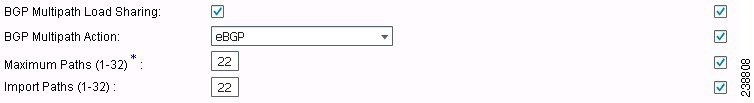
When the BGP Multipath Load Sharing check box is checked, additional fields are displayed for the BGP multipath action, maximum paths, import paths, and unequal cost routes. The additional fields appear dynamically in the GUI based on the BGP Multipath Action option you choose.
If there is no existing BGP multipath configuration, specifying multipath load sharing through these fields creates a new multipath BGP configuration for the VRF of the PE. If a BGP multipath configuration already exists, this action overwrites the existing configuration with the new multipath values. A remove option allows you to delete all existing BGP multipath configurations of a particular type for the VRF of the PE. If the BGP Multipath Load Sharing check box is unchecked, no BGP multipath actions are taken. See Removing a Multipath Configuration, for how multipath settings defined in a service request can be removed.
When a BGP multipath configuration is edited on an existing MPLS service request, all MPLS service requests on the same device with the same VPN membership are moved to the Requested state. This keeps the IPv4 and IPv6 multipath configuration synchronized.
Note ![]() For information on BGP multipath support for IOS XR devices, see BGP Multipath Support for IOS XR Devices.
For information on BGP multipath support for IOS XR devices, see BGP Multipath Support for IOS XR Devices.
BGP multipath is supported for IPv6 and dual stacked services. The BGP multipath configuration is configured for the VPN routing/forwarding instance (VRF). Thus, it is possible to set only one set of parameters for both IPv4 and IPv6 services.
The following sections describe each of the multipath scenarios, as determined by the type of BGP multipath selected in the BGP Multipath Action drop-down list. The options available in the drop-down list are:
•![]() eBGP—Specifies the multipath configuration for eBGP. This is the default selection.
eBGP—Specifies the multipath configuration for eBGP. This is the default selection.
•![]() iBGP—Specifies the multipath configuration for iBGP.
iBGP—Specifies the multipath configuration for iBGP.
•![]() eiBGP—Specifies the multipath configuration for both eBGP and iBGP. This option allows you to set a common shared value for maximum paths and import paths for both eBGP and iBGP.
eiBGP—Specifies the multipath configuration for both eBGP and iBGP. This option allows you to set a common shared value for maximum paths and import paths for both eBGP and iBGP.
•![]() eBGP+iBGP—Specifies the multipath configuration for both eBGP and iBGP. This option allows you to set the maximum paths and import paths separately for both eBGP and iBGP.
eBGP+iBGP—Specifies the multipath configuration for both eBGP and iBGP. This option allows you to set the maximum paths and import paths separately for both eBGP and iBGP.
•![]() Remove—Deletes all existing BGP multipath configurations for the VRF of the PE.
Remove—Deletes all existing BGP multipath configurations for the VRF of the PE.
Each of these scenarios is covered below.
Note ![]() When creating service requests, in the MPLS Link Editor - VPN and VRF window, an additional BGP attribute called Force Modify Shared Multipath Attributes appears in the GUI when the BGP Multipath Load Sharing check box is checked. The purpose of this attribute is to enable forced modification of the shared VRF attributes used by other links. This field is not persisted. This attribute only appears when creating service requests, not when creating policies.
When creating service requests, in the MPLS Link Editor - VPN and VRF window, an additional BGP attribute called Force Modify Shared Multipath Attributes appears in the GUI when the BGP Multipath Load Sharing check box is checked. The purpose of this attribute is to enable forced modification of the shared VRF attributes used by other links. This field is not persisted. This attribute only appears when creating service requests, not when creating policies.
eBGP Multipath
When you select the eBGP option, the Maximum Paths and Import Paths fields appear. Where:
•![]() Maximum Paths—Specifies the maximum number of routes to allow in the routing table.
Maximum Paths—Specifies the maximum number of routes to allow in the routing table.
•![]() Import Paths—Specifies the number of redundant paths that can be configured as backup multipaths for a VRF.
Import Paths—Specifies the number of redundant paths that can be configured as backup multipaths for a VRF.
Note ![]() When setting up an eBGP multipath configuration, you must set a value for either Maximum Paths or Import Paths. Both fields cannot be blank.
When setting up an eBGP multipath configuration, you must set a value for either Maximum Paths or Import Paths. Both fields cannot be blank.
iBGP Multipath
When you select the iBGP option, the Maximum Paths, Import Paths, and Unequal Cost fields appear. Where:
•![]() Maximum Paths—Specifies the maximum number of routes to allow in the routing table. You must specify a value when setting up an iBGP multipath configuration.
Maximum Paths—Specifies the maximum number of routes to allow in the routing table. You must specify a value when setting up an iBGP multipath configuration.
•![]() Import Paths—Specifies the number of redundant paths that can be configured as backup multipaths for a VRF.
Import Paths—Specifies the number of redundant paths that can be configured as backup multipaths for a VRF.
•![]() Unequal Cost—Enables/disables unequal-cost multipath. Unequal-cost multipath allows traffic to be distributed among multiple unequal-cost paths to provide greater overall throughput and reliability.
Unequal Cost—Enables/disables unequal-cost multipath. Unequal-cost multipath allows traffic to be distributed among multiple unequal-cost paths to provide greater overall throughput and reliability.
eiBGP Multipath
When you select the eiBGP option, the Maximum Paths and Import Paths fields appear. Where:
•![]() Maximum Paths—Specifies the maximum number of routes to allow in the routing table. You must specify a value when setting up an eiBGP multipath configuration.
Maximum Paths—Specifies the maximum number of routes to allow in the routing table. You must specify a value when setting up an eiBGP multipath configuration.
•![]() Import Paths—Specifies the number of redundant paths that can be configured as backup multipaths for a VRF.
Import Paths—Specifies the number of redundant paths that can be configured as backup multipaths for a VRF.
eiBGP+iBGP Multipath
When you select the eiBGP+iBGP option, the Maximum Paths, Import Paths, and Unequal Cost fields appear. Where:
•![]() Maximum Paths—Specifies the maximum number of routes to allow in the routing table. The number of routes can be specified separately for eBGP and iBGP.
Maximum Paths—Specifies the maximum number of routes to allow in the routing table. The number of routes can be specified separately for eBGP and iBGP.
•![]() Import Paths—Specifies the number of redundant paths that can be configured as backup multipaths for a VRF. The number of paths can be specified separately for eBGP and iBGP.
Import Paths—Specifies the number of redundant paths that can be configured as backup multipaths for a VRF. The number of paths can be specified separately for eBGP and iBGP.
•![]() Unequal Cost—Enables/disables unequal-cost multipath. Unequal-cost multipath allows traffic to be distributed among multiple unequal-cost paths to provide greater overall throughput and reliability.
Unequal Cost—Enables/disables unequal-cost multipath. Unequal-cost multipath allows traffic to be distributed among multiple unequal-cost paths to provide greater overall throughput and reliability.
Note ![]() The support for multipath load sharing requires unique route distinguishers (RDs) for each PE router for a VPN (VRF). This is to prevent the same RDs from being allocated to different customers. This allows the use of the same RD for the same VRF. That is, all sites in the PE can have the same unique RD. The unique RD feature is optional. It is enabled at both a global VPN level or a service request level. To enable the unique RD per PE for a VPN, the Create VPN window contains a new Enable Unique Route Distinguisher field. For more information on using this feature, see Chapter 21, "Enabling a Unique Route Distinguisher for a VPN".
The support for multipath load sharing requires unique route distinguishers (RDs) for each PE router for a VPN (VRF). This is to prevent the same RDs from being allocated to different customers. This allows the use of the same RD for the same VRF. That is, all sites in the PE can have the same unique RD. The unique RD feature is optional. It is enabled at both a global VPN level or a service request level. To enable the unique RD per PE for a VPN, the Create VPN window contains a new Enable Unique Route Distinguisher field. For more information on using this feature, see Chapter 21, "Enabling a Unique Route Distinguisher for a VPN".
BGP Multipath Support for IOS XR Devices
The following attributes are supported in Prime Fulfillment for BGP multipath configuration on IOS XR devices:
•![]() Maximum Paths—This attribute has a range from 2 to 8 for IOS XR. When an out-of-range value is specified, the service request cannot be saved and an error is displayed. The service request will not move to an Invalid state (which occurs if a deployment is carried out).
Maximum Paths—This attribute has a range from 2 to 8 for IOS XR. When an out-of-range value is specified, the service request cannot be saved and an error is displayed. The service request will not move to an Invalid state (which occurs if a deployment is carried out).
•![]() Unequal Cost—This attribute is supported for iBGP only.
Unequal Cost—This attribute is supported for iBGP only.
The Import Paths attribute is supported in IOS but not in IOS XR.
Removing a Multipath Configuration
A multipath configuration can be removed by selecting the Remove option in drop-down list of the BGP Multipath Action attribute. The Remove option removes the multipath configuration for the VRF on the PE, if it is previously configured.
If a service request is saved with a multipath configuration and the configuration has to be removed, you should use the Remove option.
Note ![]() A multipath configuration cannot be removed by simply unchecking the BGP Multipath Load Sharing check box. It must be removed by setting the BGP Multipath Action attribute to Remove, and then saving the service request. You should uncheck the BGP Multipath Load Sharing check box only after removing the multipath configuration.
A multipath configuration cannot be removed by simply unchecking the BGP Multipath Load Sharing check box. It must be removed by setting the BGP Multipath Action attribute to Remove, and then saving the service request. You should uncheck the BGP Multipath Load Sharing check box only after removing the multipath configuration.
Enabling Template Association for a Policy
The Prime Fulfillment template feature gives you a means to download free-format CLIs to devices configured for links within an MPLS service request. If you enable templates, you can use templates and data files to download commands that are not currently supported by Prime Fulfillment.
Step 1 ![]() To enable template association for the policy, click the Next button in MPLS Policy Editor - VRF and VPN Membership window.
To enable template association for the policy, click the Next button in MPLS Policy Editor - VRF and VPN Membership window.
The Template Association window appears. In this window, you can enable template support and, optionally, associate templates and data files with the policy. For instructions about associating templates with policies and how to use the features in this window, see Chapter 49, "Using Templates and Data Files with Policies and Service Requests"
Step 2 ![]() When you have completed setting up templates and data files for the policy per the instructions in the appendix, click Finish in the Template Association window to close it.
When you have completed setting up templates and data files for the policy per the instructions in the appendix, click Finish in the Template Association window to close it.
The Policies window appears.
Now that you have defined a service policy for an MPLS PE-to-CE service, the service operator can now use this policy to create and deploy a service request for a PE-CE link. For details, see Chapter 25, "MPLS VPN Service Requests."
 Feedback