Provides a reference configuration for EVPN multihoming with iBGP-based hierarchical BGP peering on Cisco Catalyst 9000 series switches.
This section provides EVPN multihoming with iBGP-based hierarchical BGP peering on Cisco Catalyst 9000 series switches.
The reference configurations for Cisco Catalyst 9000 series switches include the fabric device roles of leaf, spine, and border. Additionally, the border-spine device role is also supported.
These configuration examples incorporate various Cisco-validated best practices to support better scale and network resiliency.
iBGP-based network configuration
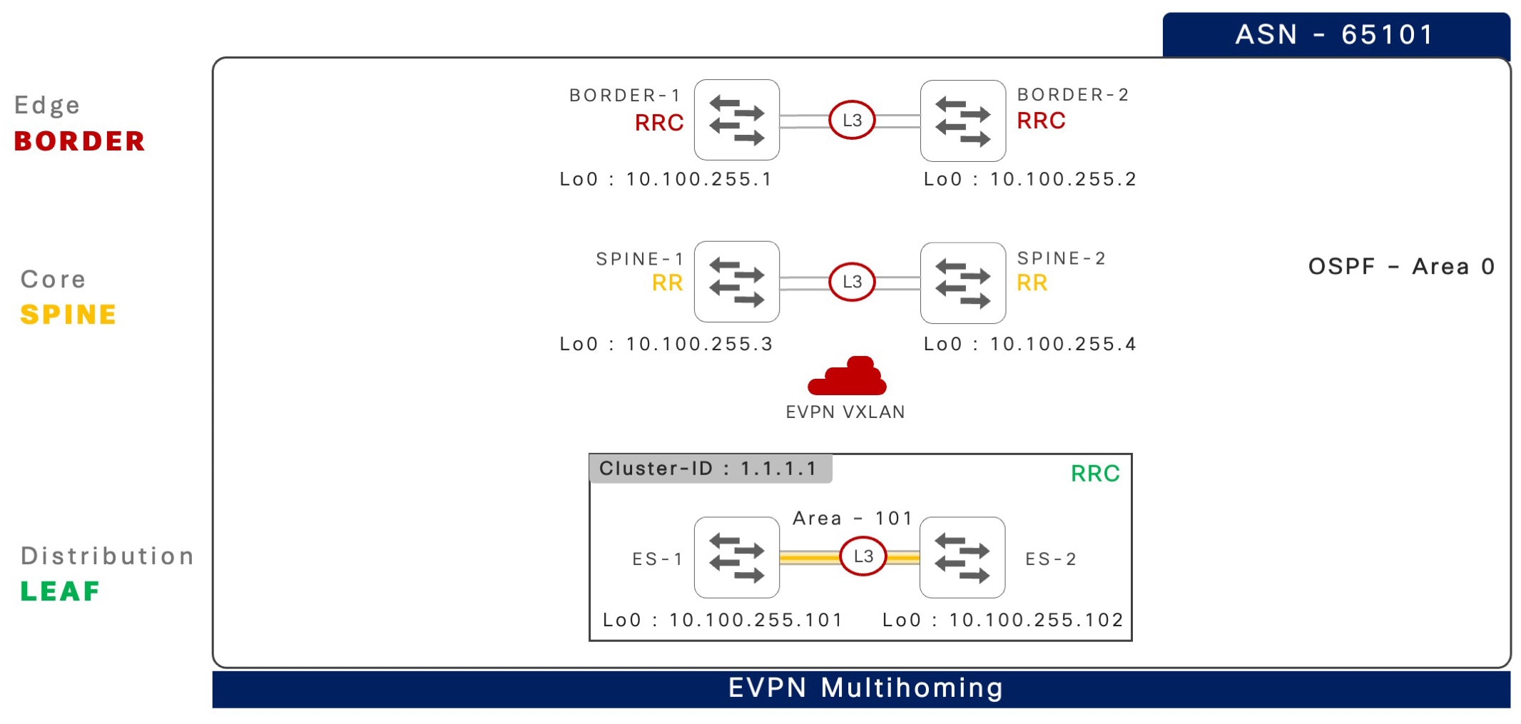
This section provides step-by-step configuration to implement EVPN multihoming with BGP EVPN fabric in an iBGP-based enterprise campus network. The underlay network built upon dynamic IGP routing protocols, such as OSPF in a multiarea network, is implemented to support large scale fabric networks with resiliency.
The following illustration shows an iBGP-based network design in a multi-tier physical network with divided unique fabric device-roles across each layer.
The following table provides Cisco-validated best practices to build a two-tier hierarchical iBGP peering between two Cisco Catalyst 9000 series switches in EVPN multihoming mode, and iBGP peering to a pair of spine switches.
Table 1. Two-tier hierarchical iBGP peering between a pair of spine switches
Step
Leaf1
Leaf 2
1: Global best practices
!
system mtu 9100
!
port-channel load-balance
  vlan-src-dst-mixed-ip-port
ip cef load-sharing algorithm
   include-ports
 source destination protocol
!
ip tcp mss 8000
ip tcp window-size 262144
ip tcp path-mtu-discovery
!
!
system mtu 9100
!
port-channel load-balance
  vlan-src-dst-mixed-ip-port
ip cef load-sharing algorithm
   include-ports
 source destination protocol
!
ip tcp mss 8000
ip tcp window-size 262144
ip tcp path-mtu-discovery
!
2: Inter-ES Layer 3 EtherChannel
!
interface Port-Channel 128
 description CONNECTED TO EVPN
    MH ES SWITCH
 no switchport
ip ospf network point-to-point
 ip ospf multi-area 0
 ip ospf 100 area 101
 ip ospf 100 cost 10
 carrier-delay msec 0
 hold-queue 4094 in
 hold-queue 4094 out
 evpn multihoming core-tracking
!
!
interface Port-Channel 128
 description CONNECTED TO EVPN
    MH ES SWITCH
 no switchport
ip ospf network point-to-point
 ip ospf multi-area 0
 ip ospf 100 area 101
 ip ospf 100 cost 10
 carrier-delay msec 0
 hold-queue 4094 in
 hold-queue 4094 out
 evpn multihoming core-tracking
!
3: IGP routing and core interfaces
!
router ospf 100
 router-id 10.200.255.101
 max-metric router-lsa include-stub
  summary-lsa external-lsa on-startup
      wait-for-bgp
 nsf cisco
 fast-reroute per-prefix enable
    prefix-priority low
 area 101 stub no-summary
 passive-interface default
 no passive-interface Port-Channel 128
 no passive-interface HundredGig1/0/49
 no passive-interface HundredGig1/0/50
!
interface Loopback 0
ip ospf 100 area 0
!
interface range HundredGig1/0/49-50
 description CONNECTED TO SPINE DEVICES
 ip ospf 100 area 0
 ip ospf network point-to-point
 carrier-delay msec 0
 hold-queue 4094 in
 hold-queue 4094 out
 evpn multihoming core-tracking
!
!
router ospf 100
 router-id 10.200.255.102
 max-metric router-lsa include-stub
  summary-lsa external-lsa on-startup
   wait-for-bgp
 nsf cisco
 fast-reroute per-prefix enable
   prefix-priority low
 area 101 stub no-summary
 passive-interface default
 no passive-interface Port-Channel 128
 no passive-interface HundredGig1/0/49
 no passive-interface HundredGig1/0/50
!
interface Loopback 0
ip ospf 100 area 0
!
interface range HundredGig1/0/49-50
 description CONNECTED TO SPINE DEVICES
 ip ospf 100 area 0
 ip ospf network point-to-point
 carrier-delay msec 0
 hold-queue 4094 in
 hold-queue 4094 out
 evpn multihoming core-tracking
!
The following table provides step-by-step reference configurations, including Cisco validated best practices to configure iBGP peering between a pair of spine and border switches.
Table 2. iBGP peering between a pair of spine and border switches
Step
Spine 1 and Spine 2
Border 1 and Border 2
1: Global best practices
!
system mtu 9100
!
port-channel load-balance
  vlan-src-dst-mixed-ip-port
ip cef load-sharing algorithm
  include-ports
 source destination protocol
!
ip tcp mss 8000
ip tcp window-size 262144
ip tcp path-mtu-discovery
!
!
system mtu 9100
!
port-channel load-balance
  vlan-src-dst-mixed-ip-port
ip cef load-sharing algorithm
  include-ports
 source destination protocol
!
ip tcp mss 8000
ip tcp window-size 262144
ip tcp path-mtu-discovery
!
2: IGP routing
Spine-1
!
router ospf 100
 router-id 10.200.255.3
 max-metric router-lsa include-stub
  summary-lsa external-lsa on-startup
   wait-for-bgp
 nsf cisco
 fast-reroute per-prefix enable
   prefix-priority low
passive-interface default
 no passive-interface Port-Channel 128
 no passive-interface HundredGig1/0/49
 no passive-interface HundredGig1/0/50
!
Spine-2
!
router ospf 100
 router-id 10.200.255.4
 max-metric router-lsa include-stub
  summary-lsa external-lsa on-startup
    wait-for-bgp
 nsf cisco
 fast-reroute per-prefix enable
   prefix-priority low
passive-interface default
 no passive-interface Port-Channel 128
 no passive-interface HundredGig1/0/1
 no passive-interface HundredGig1/0/2
 no passive-interface HundredGig1/0/3
 no passive-interface HundredGig1/0/4
!
!
interface Loopback 0
ip ospf 100 area 0
!
interface range HundredGig1/0/1-2
 description CONNECTED TO EVPN MH
   LEAF DEVICES
 ip ospf 100 area 0
 ip ospf network point-to-point
 carrier-delay msec 0
 hold-queue 4094 in
 hold-queue 4094 out
!
interface range HundredGig1/0/3-4
 description CONNECTED TO BORDER DEVICES
 ip ospf 100 area 0
 ip ospf network point-to-point
 carrier-delay msec 0
 hold-queue 4094 in
 hold-queue 4094 out
!
!
interface Loopback 0
ip ospf 100 area 0
!
interface range HundredGig1/0/49-50
 description CONNECTED TO SPINE DEVICES
 ip ospf 100 area 0
 ip ospf network point-to-point
 carrier-delay msec 0
 hold-queue 4094 in
 hold-queue 4094 out
!