Important. Results generated by AI. Before using results, verify accuracy and completeness.
Copy
Overview
Learn how to configure Secure Firewall 1210/20 interfaces, including assigning inside and outside zones and setting IP addressing for routed deployments.
When you use zero-touch provisioning or the Firewall Device Manager for initial setup instead of using the CLI, the following interfaces are preconfigured:
Ethernet 1/1—outside, IP address from DHCP, IPv6 autoconfiguration
VLAN1— inside, 192.168.95.1/24
Default route—Obtained through DHCP on the outside interface
If you performed additional interface-specific configuration within Firewall Device Manager before registering with the Firewall Management Center, then that configuration is preserved.
If you used the CLI for initial setup, there is no preconfiguration of your device.
In both cases, you need to perform additional interface configuration after you register the device. For CLI initial setup, you must add the VLAN1 interface for the inside switch ports. Additional configuration includes converting switch ports to firewall interfaces as desired, assigning interfaces to security zones, and changing IP addresses.
The following example configures a routed-mode inside interface (VLAN1) with a static address and a routed-mode outside interface using DHCP (Ethernet1/1). It also adds a DMZ interface for an internal web server.
Procedure
1.
Choose Devices > Device Management, and click Edit () for the device.
2.
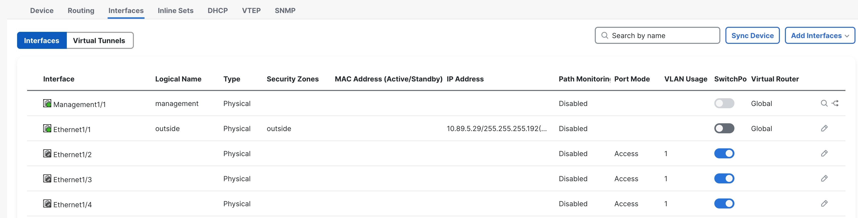
Click Interfaces.
Figure 1. Interfaces
3.
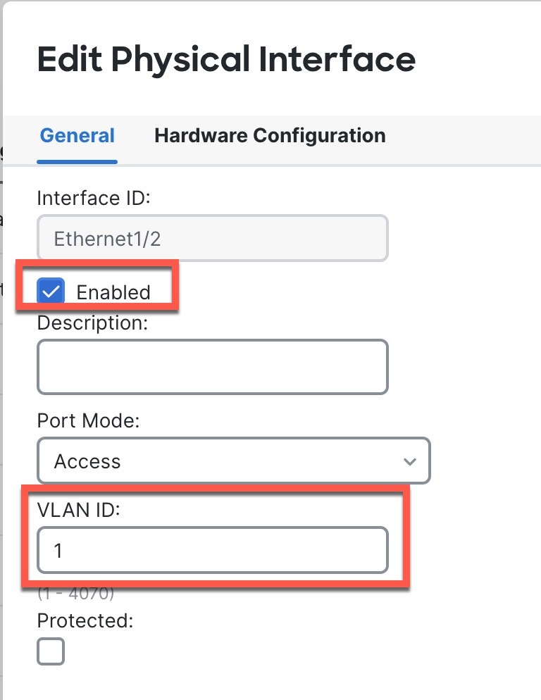
If you used the CLI for initial setup, enable the switch ports.
Click Edit () for the switch port.
Figure 2. Enable Switch Port
Enable the interface by checking the Enabled check box.
(Optional) Change the VLAN ID; the default is 1. You will next add a VLAN interface to match this ID.
Click OK.
4.
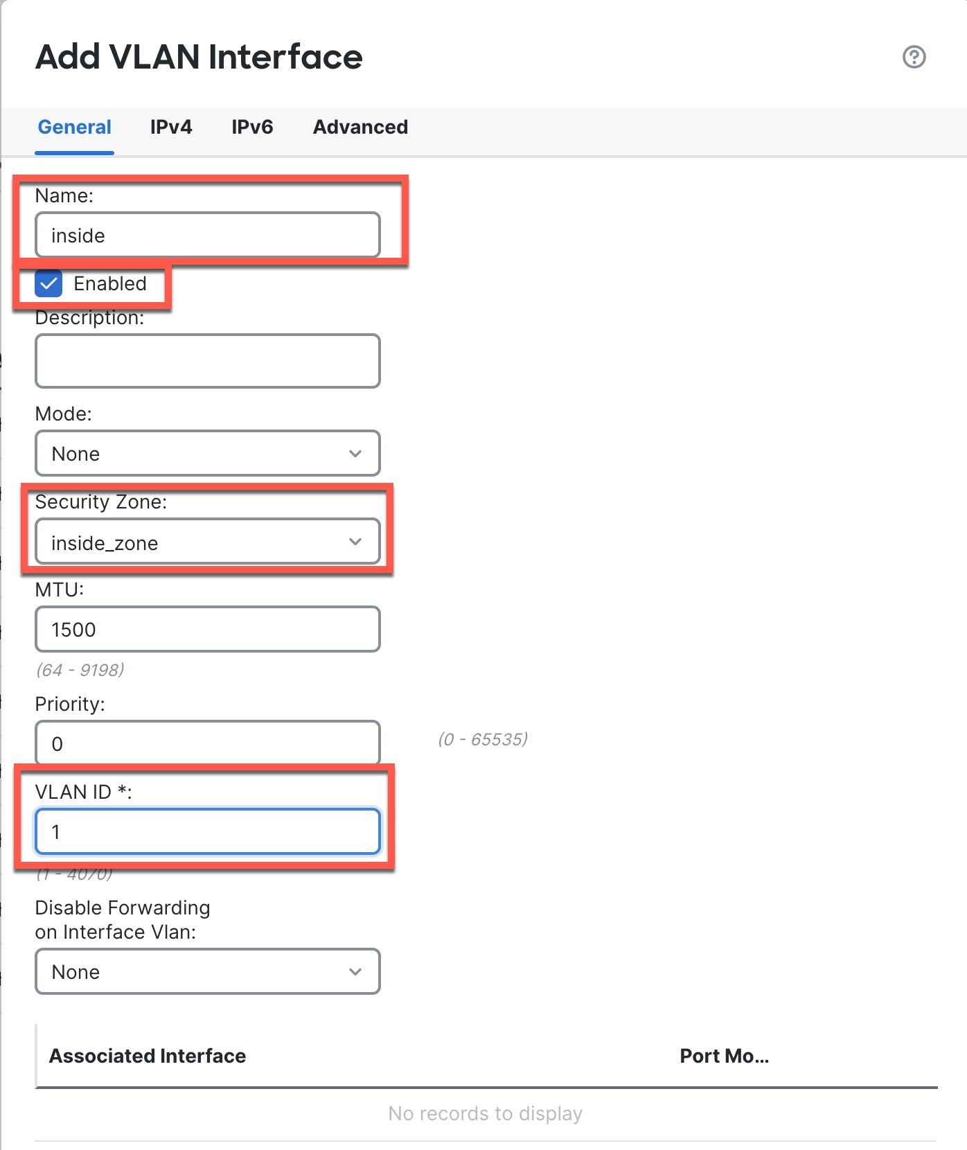
Add (or edit) the inside VLAN interface.
Click Add Interfaces > VLAN Interface, or if this interface already exists, click Edit () for the interface.
Figure 3. Add VLAN Interface
From the Security Zone drop-down list, choose an existing inside security zone or add a new one by clicking New.
For example, add a zone called inside_zone. You apply your security policy based on zones or groups.
If VLAN1 was preconfigured, the rest of these fields are optional.
Enter a Name up to 48 characters in length.
For example, name the interface inside.
Check the Enabled check box.
Leave the Mode set to None.
Set the VLAN ID to 1.
By default, all of the switchports are set to VLAN 1; if you choose a different VLAN ID here, you need to also edit each switchport to be on the new VLAN ID.
You cannot change the VLAN ID after you save the interface; the VLAN ID is both the VLAN tag used, and the interface ID in your configuration.
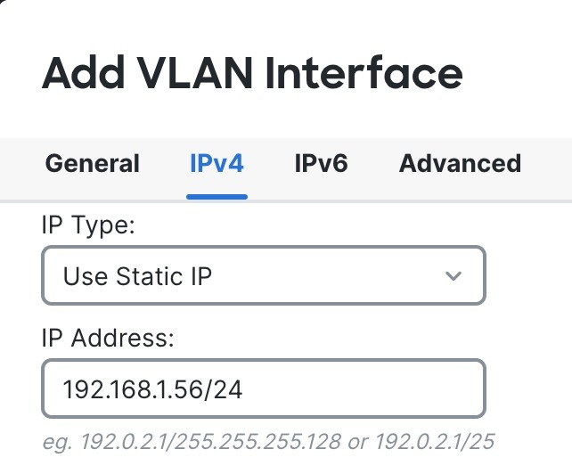
Click the IPv4 and/or IPv6 tab.
IPv4—Choose Use Static IP from the drop-down list, and enter an IP address and subnet mask in slash notation.
For example, enter 192.168.1.56/24
Figure 4. Set Inside IP Address
IPv6—Check the Autoconfiguration check box for stateless autoconfiguration.
Click OK.
5.
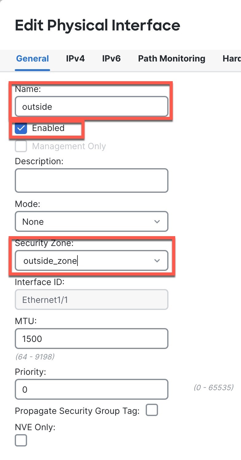
Click Edit () for Ethernet1/1 that you want to use for outside.
The General page appears.
Figure 5. General
From the Security Zone drop-down list, choose an existing outside security zone or add a new one by clicking New.
For example, add a zone called outside_zone.
You should not alter any other basic settings because doing so will disrupt the Firewall Management Center management connection.
Click OK.
6.
Configure a DMZ interface to host a web server, for example.
Disable switch-port mode for the switch port you want to use for the DMZ by clicking the slider in the SwitchPort column so it shows as disabled ().
Click Edit () for the interface.
From the Security Zone drop-down list, choose an existing DMZ security zone or add a new one by clicking New.
For example, add a zone called dmz_zone.
Enter a Name up to 48 characters in length.
For example, name the interface dmz.
Check the Enabled check box.
Leave the Mode set to None.
Click the IPv4 and/or IPv6 tab and configure the IP address as desired.