System Setup and Software Installation Guide for Cisco NCS 1014, IOS XR Releases 26.x.x

PDF

System Setup and Software Installation Guide for Cisco NCS 1014, IOS XR Releases 26.x.x

How OLT line card connection verifications work

Want to summarize with AI?

Log in

Describes how Optical Line Terminal (OLT) line cards use out-of-band channels and photodiode monitors to verify connections with NCS1K-CCMD-16 line cards.


Summary

Line card connection verification ensures the integrity and correct identification of optical paths between OLTs and NCS1K-CCMD-16 line cards. This process relies on specialized channels, modulated signals, and dedicated photodiode monitors.

The key components involved in the process are:

  • OLT line card: Generates the verification tone and manages the initiation of the connection test.

  • Connection Verification Tunable Laser (CV-TL): Produces a modulated tone at 191.175 THz, embedding the Cable ID pattern to identify the optical path.
  • Photodiode monitors (PD21 and PD22 on the CCMD-16 card): Detect and buffer the Cable ID pattern from the incoming verification signals for validation by the node controller.

Connection verification between an OLT and NCS1K-CCMD-16 line cards is vital for maintaining reliable optical communication. Embedding the Cable ID in the verification signal helps identify the path under test and validates both out-of-band (OOB) and in-band (IB) connections.

Workflow

The process involves these stages:

  1. Tone generation: The OLT line card initiates the process by generating a verification tone using the CV-TL tuned at 191.175 THz.
  2. Cable ID modulation: The CV-TL tone is modulated with a low-frequency pattern that includes the Cable ID of the specific connection.
  3. Signal routing: The modulated CV-TL signal is transmitted via the OOB channel toward the CCMD-16 line card.
  4. Path identification: For verification toward the CCMD-16 card, the CV-TL signal is routed to photodiode PD21 (for OOB verification) and PD22 (for IB verification).
  5. Signal detection and buffering: PD21 or PD22 detects the verification signal and buffers the encoded Cable ID pattern.
  6. Verification by node controller: The node controller reads the buffered Cable ID pattern and confirms the identity and integrity of the optical path under test.

Result

This process enables automated, accurate verification of optical connections between OLTs and NCS1K-CCMD-16 line cards, ensuring each link is correctly identified and operational.

Verify connection for a CCMD-16 line card

Use this task to verify that the NCS 1010 OLT-C line card and the NCS1K-CCMD-16 line card are connected correctly.

The connection verification procedure checks the connection between the OLT line card and CCMD-16 line cards to match the different instances with the OLT line-card connectors.

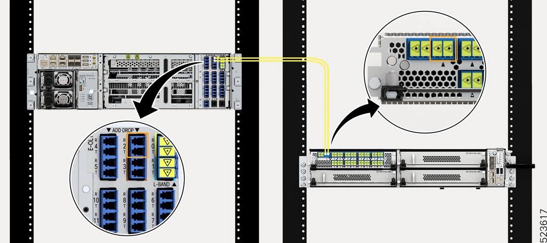
The OLT-C line card and the NCS1K-CCMD-16 line card are connected as shown in the figure.

Figure 1. NCS 1010 and NCS1K-CCMD-16 connection

The OLT-C line card performs connection verification between the OLT-C line card and the NCS1K-CCMD-16 line card panels as described in How OLT line card connection verifications work.

The NCS1K-CCMD-16 line card is identified and verified by checking the connection verification signal at the monitors on the out-of-band (OOB) and in-band (IB) loops. PD21 monitors the OOB loop, and PD22 monitors the IB loop for the NCS1K-CCMD-16 line card.

Before you begin

Configure the Optical Transport Section (OTS) controller in Cisco NCS 1010 to generate the tone for connection verification. For details about configuring the OTS controller, see Cisco NCS 1010 Datapath Configuration Guide.

Procedure

1.

Configure the Optical Multiplex Section (OMS) controller to detect the tone for connection verification.

Example:

RP/0/RP0/CPU0:(config)#controller oms 0/1/0/0
RP/0/RP0/CPU0:(config-Oms)#tone-rate 2
RP/0/RP0/CPU0:(config-Oms)#tone-pattern-expected aabbccdd
RP/0/RP0/CPU0:(config-Oms)#tone-detect-oob
RP/0/RP0/CPU0:(config-Oms)#commit

Configure tone-detect-oob on the OMS x/x/x/0 controller for NCS1K-CCMD-16.

2.

Start tone-pattern detection on the OMS controller with the tone-pattern-detect command.

Example:

This sample starts tone-pattern detection on the OMS controller.

RP/0/RP0/CPU0:#tone-pattern-detect controller oms 0/1/0/0 start
Tue May 10 11:38:03.775 UTC
Tone pattern detect started
3.

Check the tone information with the tone-info command.

Example:

This sample shows successful connection verification on the OMS controller.

RP/0/RP0/CPU0:#show controllers oms 0/1/0/0 tone-info
Fri Sep 22 06:04:03.787 UTC
Tone Info:
Tone Rate : 2 bits/second
Tone Pattern Expected(Hex value) : aabbccdd
Tone Pattern Received(Hex value) : aabbccdd
Tone Detected OOB :  Enabled
Detection State: Success
4.

Stop tone-pattern detection on the OMS controller after connection verification succeeds.

Example:

RP/0/RP0/CPU0:#tone-pattern-detect controller oms 0/1/0/0 stop
Fri Sep 22 06:23:15.165 UTC
Tone pattern detect stopped

The expected and received tone patterns match, and the detection state is Success.