Cisco Al POD for Enterprise Training and Fine-Tuning with Everpure Deployment Guide
Available Languages
Bias-Free Language
The documentation set for this product strives to use bias-free language. For the purposes of this documentation set, bias-free is defined as language that does not imply discrimination based on age, disability, gender, racial identity, ethnic identity, sexual orientation, socioeconomic status, and intersectionality. Exceptions may be present in the documentation due to language that is hardcoded in the user interfaces of the product software, language used based on RFP documentation, or language that is used by a referenced third-party product. Learn more about how Cisco is using Inclusive Language.
- US/Canada 800-553-2447
- Worldwide Support Phone Numbers
- All Tools
 Feedback
 Feedback
Published: March 2026
In partnership with:
![]()
![]()
About the Cisco Validated Design Program
The Cisco Validated Design (CVD) program consists of systems and solutions designed, tested, and documented to facilitate faster, more reliable, and more predictable customer deployments. For more information, go to: http://www.cisco.com/go/designzone.
Executive Summary
This document provides prescriptive step-by-step procedures for deploying a Cisco AI POD solution with Everpure FlashBlade//S for enterprise training and fine-tuning. The solution is based on one of several design options presented in the Cisco AI POD for Enterprise Training and Fine-Tuning Design Guide. The implementation details enable infrastructure engineers and AI/ML practitioners to quickly build, configure, and operationalize a high-performance AI cluster.
Cisco AI PODs are modular, validated infrastructure solutions that are designed to meet enterprise AI infrastructure requirements. These solutions integrate dense GPU platforms, high-performance networking, storage, enterprise-class Kubernetes, and MLOps to deliver a complete stack for enterprise AI initiatives. The architecture takes a building-block approach using Scale Unit Types, enabling organizations to start with deployments of 32-, 64-, or 128-GPU clusters. These foundational building blocks can then scaled incrementally and predictably to support 256, 512, or higher GPU clusters as requirements evolve.
This solution was built and validated in Cisco labs and consists of Cisco UCS C-Series GPU servers, specifically Cisco UCS C885A M8 servers, in a dual-fabric architecture. The designs include a backend (East-West) fabric optimized for low-latency GPU-to-GPU communication and a frontend (North-South) fabric for cluster management, services, storage I/O, and other connectivity. Both fabrics are deployed using pre-built, best-practice templates available in Cisco Nexus Dashboard. The solution also includes a Cisco UCS X-Series Direct-based cluster for management and other services, provisioned and managed using Cisco Intersight in the cloud.
Storage is provided by Everpure FlashBlade//S, an all-flash, scale-out, file and object platform. The procedures detail the configuration of FlashBlade to support the AI data pipeline using both NFS-based file services for active training datasets and S3-compatible object storage to serve as a data and model repository. Portworx by Everpure, backed by NFS storage on Pure FlashBlade//S, is also included in the solution to provide persistent data services to containers natively in Kubernetes. This multi-protocol approach ensures the storage layer supports the entire data lifecycle, from initial ingestion to long-term archiving.
The solution supports both Linux and Kubernetes software stacks but was validated with Red Hat OpenShift to provide customers with a consistent, enterprise-class software stack for training that aligns with AI inference and non-AI environments that may already be in place. For organizations requiring a comprehensive development environment to accelerate AI initiatives, the solution also includes Red Hat OpenShift AI as an MLOps platform to manage the lifecycle of AI initiatives, from model development to production deployment.
Centralized management is provided through Cisco Intersight and Nexus Dashboard, enabling automation and operational visibility. Intersight manages the complete lifecycle of the Cisco UCS X-Series management cluster while providing hardware visibility and monitoring for the UCS dense GPU nodes. The solution validation includes functional verification and platform-level validation using the NVIDIA Collective Communications Library (NCCL) to ensure the cluster performs as expected.
This deployment guide, along with the Cisco AI POD for Enterprise Training and Fine-Tuning Design Guide and the associated GitHub repository, serves as the full set of deliverables for this AI POD CVD. To access all Cisco AI POD CVDs, navigate to: Cisco Validated Design Zone for AI-Ready Infrastructure.
Solution Overview
This chapter contains the following:
AI/ML is rapidly transforming enterprise organizations, driving a need for reliable, scalable, and secure AI-ready infrastructure. This guide provides detailed procedures for deploying a complete AI infrastructure stack for model training and fine-tuning in enterprise data centers.
The solution in this guide consists of a 4-node, 32-GPU cluster utilizing Scale Unit – Type 1 as the foundational building block. This configuration was validated using Cisco UCS C885A M8 servers with NVIDIA H200 GPUs, connected to two network fabrics and integrated with high-performance file and object storage provided by Everpure FlashBlade//S. Cisco Nexus Dashboard (ND) is used to provision and manage the two fabrics (Backend/East-West, Frontend/North-South), built using Cisco Nexus 9000 Series switches.
This guide is for IT architects, infrastructure engineers, and AI/ML practitioners responsible for the deployment, configuration, and operation of AI/ML infrastructure in enterprise data centers. Basic understanding of Cisco UCS compute platforms, Cisco Nexus networking, enterprise storage concepts, and Kubernetes is assumed.
While the AI POD Design Guide details the architecture and design options, this CVD document provides the configuration procedures for building and operationalizing a specific Cisco AI POD design. By following the procedures in this document, engineering teams can build and quickly operationalize an AI cluster that aligns with established best practices.
The Cisco AI POD solution in this document is a fully integrated solution with high-density compute, high-performance networking, scale-out storage, and a robust software stack, designed for Enterprise Training and Fine-Tuning. This guide provides detailed implementation guidance for deploying a 32-GPU cluster and covers the configuration of compute, network, storage, and the software stack required to support distributed training and fine-tuning workloads. It also includes comprehensive validations to ensure that the integrated subsystems are functioning as expected. The integrated solution consists of the following components:
● Cisco UCS C885A M8 Servers: Four nodes, each equipped with eight NVIDIA H200 GPUs (SXM) and dual AMD EPYC processors. These servers provide the primary compute power for distributed training and fine-tuning. Within the server, GPUs are interconnected via NVIDIA NVLink, delivering 900 GB/s of bidirectional bandwidth per node.
● Cisco UCS X-Series Direct: A dedicated management cluster used to host the control plane and management services for the Red Hat OpenShift cluster with UCS C885A worker nodes.
● Network: Dual-fabric architecture (Backend and Frontend) utilizing Cisco Nexus 9000 Series switches, managed and deployed using Cisco Nexus Dashboard.
● Backend (East-West) Fabric: Four Cisco Nexus 9332D-GX2B switches connected in a two-tier spine-leaf Clos-based topology. This fabric provides a dedicated, non-blocking 400GbE environment for GPU-to-GPU communication via RoCEv2.
● Frontend (North-South) Fabric: Four Cisco Nexus 9332D-GX2B switches, two as compute + management leaf switches and two as dedicated storage leaf switches. This fabric provides connectivity for cluster management, storage I/O, and user access.
● Cisco Intersight: Provides hardware health monitoring and visibility for the Cisco UCS C885A M8 GPU nodes while managing the complete lifecycle of the Cisco UCS X-Series management cluster.
● Cisco Nexus Dashboard: Serves as the centralized automation and operations platform for the network fabrics in the solution, providing full life-cycle management and best-practice based templates to quickly deploy and stand up both the backend and frontend fabrics.
● Everpure FlashBlade//S500: An all-flash, scale-out, unified file and object storage platform providing up to 6PB of storage capacity per system. In this CVD, FlashBlade is configured to provide high-performance NFS file services for active training datasets and S3-compatible object storage for data ingestion and to serve as a model and pipeline-artifacts repository.
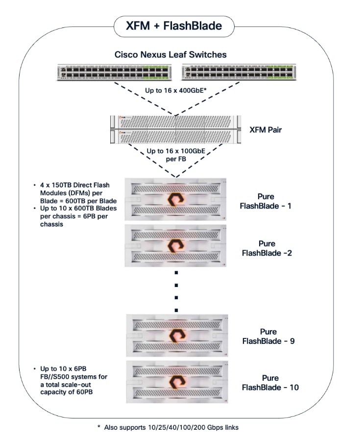
● Everpure eXternal Fabric Modules (XFM): A pair of 400GbE fabric modules is deployed as an aggregation layer to connect the FlashBlade to the Nexus storage leaf switches in the frontend fabric. XFM is Everpure's dedicated, multi-chassis fabric component for building scalable FlashBlade systems. The XFM pair provides a high-bandwidth internal network and Top-of-Rack (ToR) uplinks to enable a scale-out architecture capable of supporting up to 10 FlashBlade chassis and a total storage capacity of 60PB. The tight integration with Purity//FB enables the entire system to be managed as a single, unified system regardless of the number of chassis deployed.
● Portworx by Everpure: Kubernetes-native data platform that provides a complete container data management solution. It provides file services natively to Kubernetes containers for persistent storage, backup, disaster recovery and data security.
● Red Hat OpenShift: The solution is validated using Red Hat OpenShift Container Platform, providing a secure, enterprise-class Kubernetes-native environment for containerized AI workloads.
● NVIDIA AI Enterprise (NVAIE): A comprehensive suite of AI software that includes optimized drivers, CUDA libraries, and the NVIDIA Collective Communications Library (NCCL) required for performant distributed training.
● Red Hat OpenShift AI: Integrated to provide a collaborative development environment. It enables data scientists to manage the entire lifecycle of AI initiatives, from data preparation and model development to pipeline orchestration.
● Splunk Observability Cloud: Delivers full-stack visibility by correlating metrics and telemetry across the compute, network, and storage layers to accelerate troubleshooting.
Solution Design
This chapter describes the specific infrastructure design that was built and validated in Cisco labs to provide a high-performance environment for enterprise model training and fine-tuning.
This chapter contains the following:
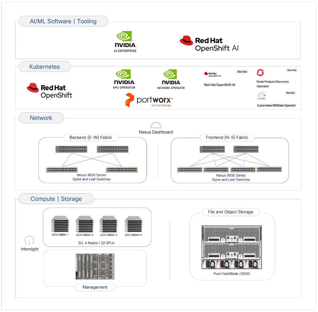
The Cisco AI POD architecture is a modular, building-block design using Scale Unit Types that can be predictably and incrementally scaled to support large GPU clusters as described in the Cisco AI POD for Enterprise Training and Fine-Tuning Design Guide. Figure 1 illustrates the logical infrastructure stack, highlighting the key components and layers integrated and validated in this solution.
This section provides the specific hardware and software components used in this deployment.
| Component (PID) |
Quantity |
Notes |
| UCS GPU Cluster |
||
| Cisco UCS C885A M8 Servers |
4 Nodes |
|
| NVIDIA H200 SXM5 GPUs |
32 GPUs (total), 8 GPUs per server |
141GB of HBM3e memory each |
| NVIDIA ConnectX-7 NICs |
8 NICs per server |
1x 400GbE NIC > backend fabric |
| NVIDIA BlueField-3 NICs |
1 NIC per server |
2x 200GbE NIC > frontend fabric |
| Backend Fabric |
||
| Cisco Nexus 9332D-GX2B |
2 Spine, 2 Leaf Switches |
400GbE fabric |
| Frontend Fabric |
||
| Cisco Nexus 9364D-GX2A |
2 Spine Switches |
400GbE from Spine to Leaf |
| Cisco Nexus 9332D-GX2B |
2 Compute, 2 Storage Leaf Switches |
200GbE to UCS, 400GbE to storage |
| UCS Management Cluster |
||
| Cisco UCS X-Series Direct |
|
|
| UCS X9508 Chassis (UCSX-9508) |
1 |
|
| UCS X Direct 100G (UCSX-S9108-100G) |
2 |
|
| UCS X210c M7 Servers (UCSX-210C-M7) |
3 OpenShift Control Nodes |
|
| VIC 15231 MLOM (UCSX-ML-V5D200G) |
3 (2x100G mLOM) |
To connect to frontend fabric |
| Storage - Unified File and Object |
||
| Everpure FlashBlade//S500 |
1 |
|
| Everpure XFM-8400R2 |
2 |
Fabric modules providing 400GbE aggregation |
| Software |
||
| Red Hat OpenShift |
|
Workload Orchestrator |
| Red Hat NFD Operator |
N/A |
|
| NVIDIA GPU Operator |
N/A |
|
| NVIDIA Network Operator |
N/A |
|
| Portworx Enterprise (Operator) |
N/A |
Portworx by Everpure |
| Red Hat NMState Operator |
N/A |
|
| Red Hat OpenShift AI Operator |
N/A |
|
| NVIDIA AI Enterprise (NVAIE) |
N/A |
|
| Red Hat OpenShift AI |
N/A |
MLOps Platform |
| Cisco Nexus Dashboard |
3 |
3-node physical cluster |
| Cisco Intersight |
N/A |
SaaS platform |
| Splunk Observability Cloud |
N/A |
SaaS platform |
The solution architecture consists of two independent fabrics, the backend and frontend, implemented as a two-tier spine-leaf (Clos) topology to ensure predictable, low-latency communication across the cluster. Both fabrics utilize an MP-BGP VXLAN EVPN architecture, providing flexible Layer 2 and Layer 3 overlays across a high-performance IP underlay.
The fabrics are centrally managed by Cisco Nexus Dashboard, while Cisco Intersight is used for the Cisco UCS compute servers. Figure 2 illustrates the end-to-end solution topology that was built and validated in Cisco labs.
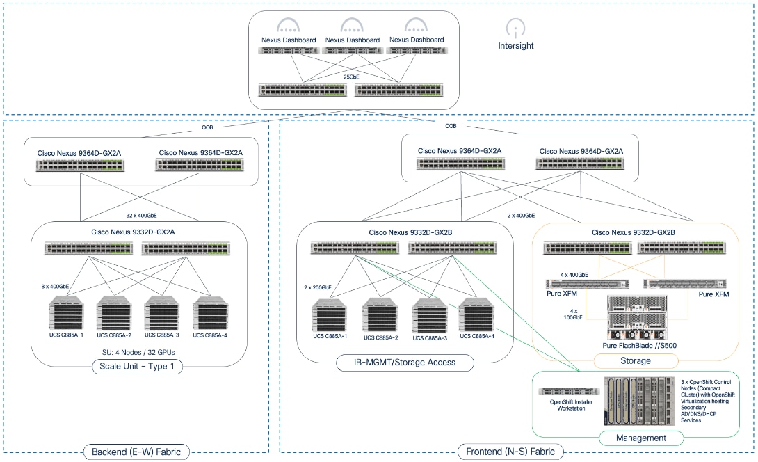
The key building blocks of this AI POD solution are:
Backend (East-West) Fabric: A dedicated, non-blocking 400GbE fabric utilizing a spine-leaf Clos topology and optimized for inter-node GPU-to-GPU communication. For this CVD, the fabric was built using two Nexus spine switches and two leaf switches. This fabric can be scaled to support a 128-GPU cluster by adding leaf pairs, and further expansion by adding both spine and leaf pairs.
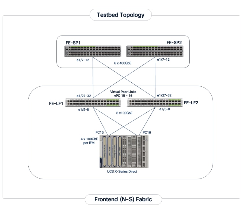
Frontend (North-South) Fabric: A 400GbE-capable spine-leaf fabric providing connectivity for all other services, including management, user access, storage, and other services. In this design, the fabric consists of two spine switches and four leaf switches as outlined below. This fabric can also be scaled as needed by adding or upgrading links or adding switch pairs.
● Compute/Management Leaf Pair: Provides 200GbE connectivity for Cisco UCS C885A nodes and 100GbE connectivity for the Cisco UCS X-Series Direct management cluster, utilizing multiple links in each case.
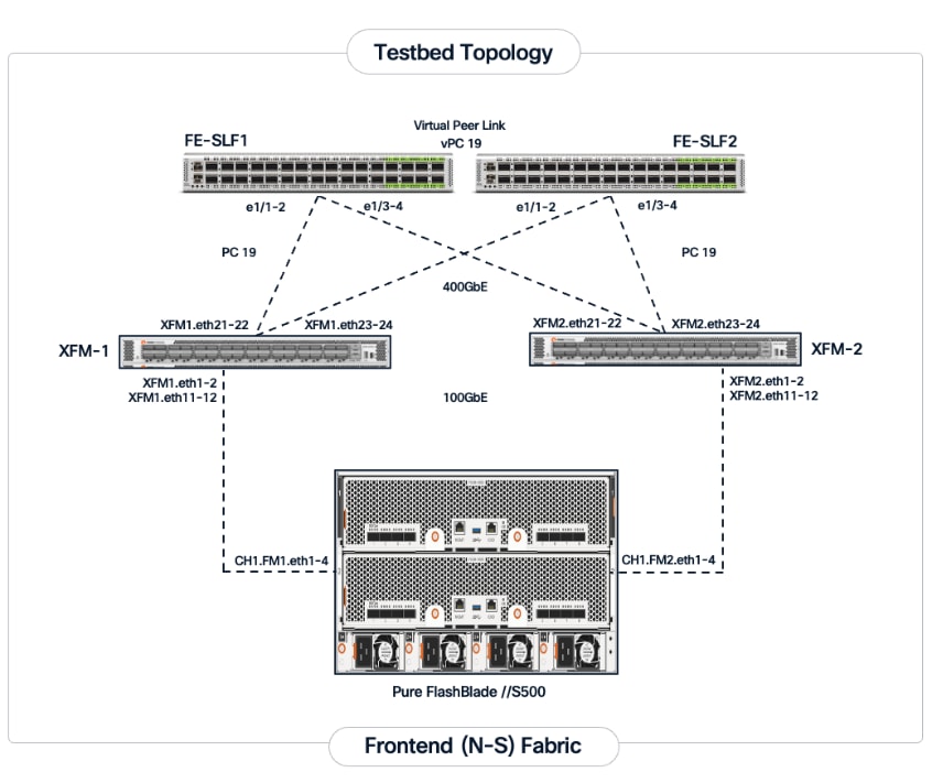
● Dedicated Storage Leaf Pair: Provides 400GbE connectivity to Everpure XFMs that connect to the FlashBlade//S storage in the solution. Multiple links are used to connect the leaf switches to the storage subsystem. This architecture enables storage to scale as GPU clusters expand to support enterprise needs.
The frontend fabric can also be scaled by adding switch pairs or by upgrading to higher-bandwidth links.
Scale Unit Types: The implementation in this CVD is based on Scale Unit – Type 1 (Figure 3), providing a 32-GPU cluster utilizing Cisco UCS C885A M8 servers with H200 GPUs, Cisco Nexus 9000 Series switches, Everpure FlashBlade//S, and Red Hat OpenShift integrated to deliver a unified infrastructure stack. To form this 32-GPU cluster, four Cisco UCS C885A M8 servers are connected to two 32-port, 400GbE Nexus 9332D-GX2B leaf switches in the backend fabric. Each server connects to the backend and frontend fabrics using eight East-West (E-W) NICs and one North-South (N-S) NIC, respectively.
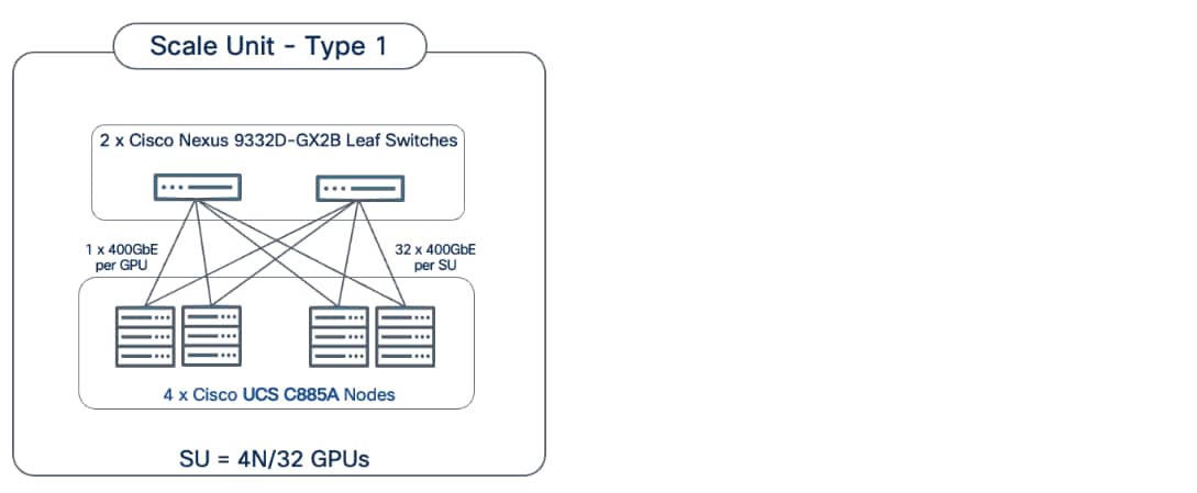
This design can scale to a 128-GPU cluster by adding scale units of the same type, and to larger cluster sizes by adding both spine pairs and scale units. Note that scale unit types do not need to remain uniform during expansion, provided the backend fabric remains non-blocking and the switches have sufficient port density to support the configuration.
The physical connectivity of the AI POD is designed to maximize throughput and minimize latency while maintaining architectural predictability and consistency as the cluster scales to support evolving needs. This section details the cabling and connectivity implemented in this design.
Backend (East-West) Connectivity
The backend fabric is engineered to provide non-blocking connectivity between GPU servers in the cluster. This is achieved by ensuring that the number of uplinks from leaf-to-spine are equal in number and bandwidth to the number of downlinks from leaf-to-UCS server. As illustrated in Figure 4, the total number of 400GbE host-facing ports on the leaf switches (32 ports across 4 nodes) is matched by an equal number of 400GbE uplinks to the spine layer, ensuring that GPU synchronization traffic does not encounter oversubscription issues due to a lack of bandwidth.
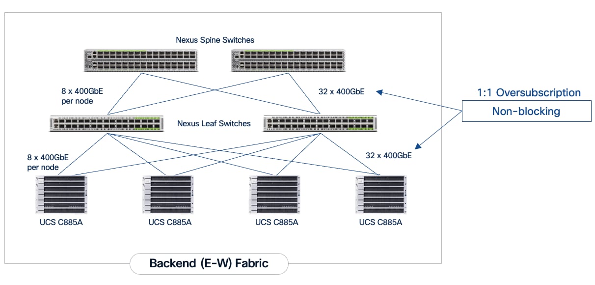
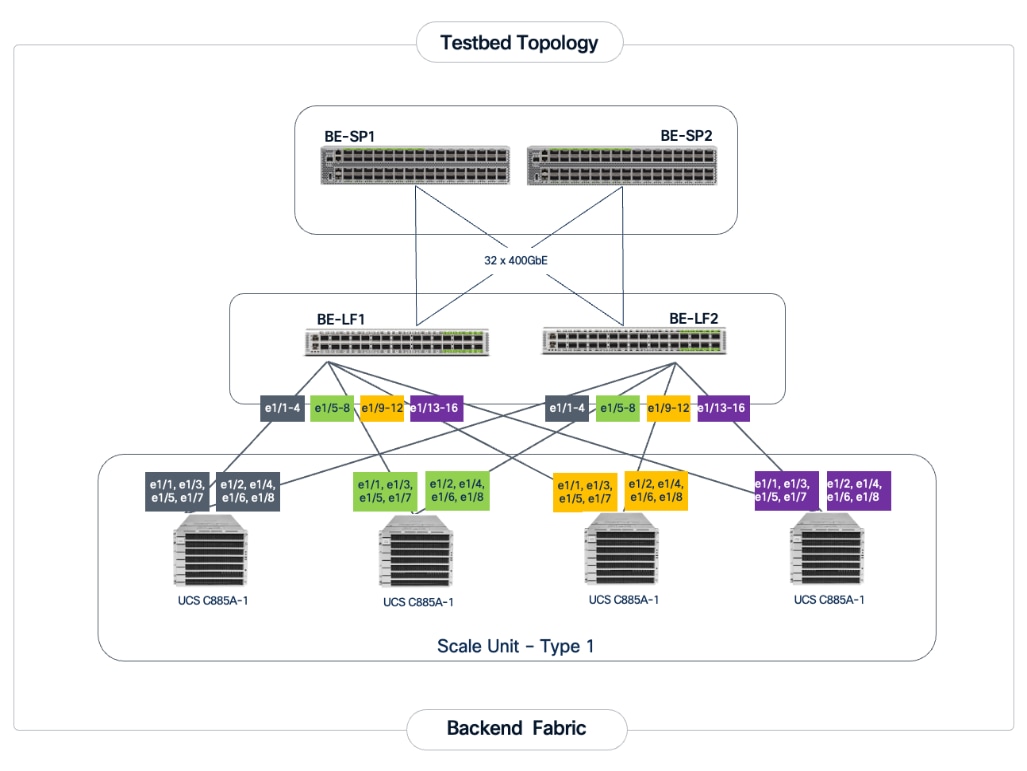
Each Cisco UCS C885A node is connected to the two leaf switches in the fabric using a 2-way rail-optimized topology. To achieve this, the eight 400GbE connections from each server are distributed across the two leaf switches in the Scale Unit – Type 1. This ensures that GPUs of the same rank, across all nodes in the Scale Unit, connect to the same physical leaf switch, minimizing the network hops required for critical collective operations.
Table 2. Backend Fabric Connectivity
| From |
GPU NICs |
To |
Port Speed |
Connectivity |
| UCS C885A (1-4) |
NICs 1, 3, 5, 7 |
Leaf Switch 1 |
400GbE |
Access VLAN |
| UCS C885A (1-4) |
NICs 2, 4, 6, 8 |
Leaf Switch 2 |
400GbE |
Access VLAN |
| Leaf Switch 1 |
16 x Uplinks – evenly distributed across Spines |
Spine Switch 1-2 |
400GbE |
Routed |
| Leaf Switch 2 |
16 x Uplinks – evenly distributed across Spines |
Spine Switch 1-2 |
400GbE |
Routed |
Each Cisco UCS C885A server is equipped with eight NVIDIA ConnectX-7 (1 x 400GbE) NICs, one per GPU to connect to the backend fabric. NVIDIA BlueField-3 NICs can also be used for East-West connectivity.
Figure 5 illustrates the backend topology used to validate this solution.
Frontend (North-South) Connectivity
The frontend fabric provides connectivity for cluster management, storage, services, users, and other networks, both inside and outside the enterprise. The frontend fabric utilizes link aggregation and 802.1Q trunking to provide a resilient, high-bandwidth path for all traffic. Table 3 lists the endpoint connectivity used in the frontend fabric.
Table 3. Frontend Fabric Connectivity
| From |
To |
Connectivity |
Traffic Type |
| UCS C885A Nodes |
Compute Leaf Pair |
2-Port LACP Bond |
VLAN Trunk |
| UCS X-Series Direct |
Compute Leaf Pair |
Multi-Port LACP |
VLAN Trunk (Management/Control) Plane) |
| Everpure XFMs |
Storage Leaf Pair |
Multi-Port LACP Bond |
VLAN Trunk |
Each Cisco UCS C885A server is equipped with one NVIDIA BlueField-3 B3220 (2 x 200GbE) NIC for connecting to the frontend fabric. The two ports on the frontend NIC are bundled into an LACP port channel. This bond is configured as a VLAN trunk, allowing management and storage traffic to share the high-speed path while remaining logically isolated. Additional NICs can be added as needed to meet evolving requirements. The detailed connectivity from Cisco UCS C885A nodes to the compute/management leaf pair is shown in Figure 6.
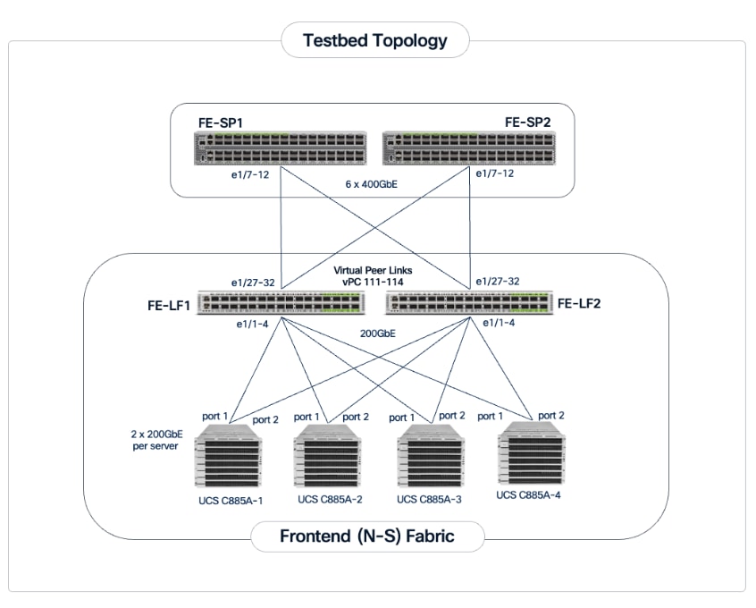
The Cisco UCS X-Series management cluster connects to the same compute leaf switches using multiple 100GbE links (Figure 7). The frontend fabric also provides connectivity to Cisco Intersight in the cloud, which is used to deploy and manage this environment.
For a high-bandwidth connectivity to Everpure FlashBlade//S storage, Everpure XFMs are deployed as a storage aggregation layer to connect to a pair of dedicated storage leaf switches. The Everpure XFMs use a LACP port channel to connect to the storage leaf switches, with multiple 400GbE links to support concurrent, high-bandwidth access to NFS and S3-compatible object storage. The detailed connectivity from Pure FlashBlade to the storage leaf pair is shown in Figure 8.
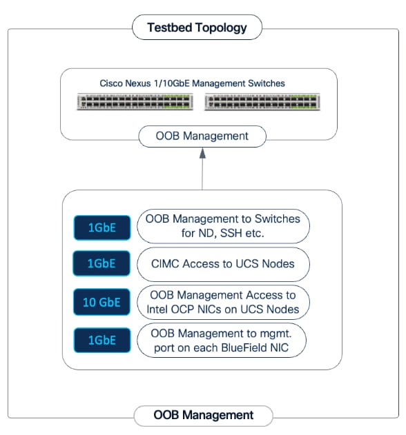
Out-of-Band Management Network
A dedicated 1GbE/10GbE Out-of-Band (OOB) management network is deployed to connect to all devices in the solution. This ensures that administrators have backup access to server consoles, management ports on NVIDIA BlueField-3 NICs, Nexus management ports, and storage controllers, independent of the state of the high-speed data fabrics. This network is also used for the initial provisioning of Cisco UCS C885A servers (via Cisco BMC, Redfish). Cisco provides a 48 port 10GBASE-T switch (Cisco Nexus 93108TC-FX3) that can be used for this network.
This section outlines the design of the compute, network, storage, and other subsystems in the validated AI POD solution.
Cisco Nexus Dashboard and Cisco Intersight are used to provide unified management for the network and compute infrastructure, respectively. A three-node Nexus Dashboard cluster is deployed on dedicated servers within the enterprise network. This cluster must be operational before the backend and frontend fabrics can be deployed.
Backend (East-West) Fabric
The backend fabric is a lossless, low-latency, high-throughput ethernet fabric, designed to support the stringent performance requirements of GPU-to-GPU RDMA communication. This fabric is exclusively for inter-node RDMA over Ethernet (RoCEv2) GPU communication. As stated earlier, the fabric is deployed as a two-tier spine-leaf Clos topology using a MP-BGP VXLAN EVPN architecture, which provides a multi-tenant environment with flexible support for both scalable Layer 2 and Layer 3 overlays across an IP underlay.
The fabric is deployed using a pre-built AI VXLAN EVPN fabric template available in Cisco Nexus Dashboard. This template implements a prescriptive, best-practice design for the backend fabric as shown in Figure 10. While the template provides a specific configuration, organizations retain flexibility to customize the template as needed.

Once the switches are physically connected in a Clos-based spine-leaf topology, these templates enable the fabric to be provisioned and deployed quickly. In this design, the two-spine, two-leaf backend fabric would have required 400 lines (Figure 11) of manual configuration but it was deployed in minutes using the template workflow.
To enable inter-node GPU-to-GPU communication across the backend fabric, this design uses a Layer 2 overlay where all 32 GPUs in the cluster reside in the same VLAN. This is a viable option for enterprise deployments with multiple, smaller workloads that require a smaller subset of a larger cluster for any given workload. Alternatively, a Layer 3 overlay can also be used to enable this connectivity. The UCS GPU worker node configurations may need to change to align with the design used.
To create a lossless environment for RoCEv2 traffic, a default QoS policy is implemented by the deployed AI/ML template to enable the following QoS features on the backend fabric.
● Traffic Classification: A dedicated class-map (COS 3) is used to classify RoCEv2 synchronization traffic.
● Priority Flow Control (PFC): PFC is enabled on COS 3 to provide hop-by-hop flow control. In the event of congestion, this ensures that the switch can signal the upstream device to pause transmission, preventing packet loss.
● Explicit Congestion Notification (ECN): ECN is configured with specific WRED (Weighted Random Early Detection) thresholds. As buffers begin to fill, this enables the Nexus switches to mark packets signaling GPU endpoints to throttle their transmission rate before PFC is triggered, maintaining a smooth data flow.
● MTU: A global MTU of 9000 (Jumbo Frames) is applied across all links in the fabric to ensure large AI data packets are switched efficiently without fragmentation.
In this design, the default QoS policy within the deployed template was modified as listed:
● MTU for PFC3 traffic changed from 4200 to 9216
● QoS Bandwidth Allocation for the RoCEv2 queue was adjusted to 90 percent since the backend fabric primarily carries GPU-to-GPU RDMA traffic. The remaining bandwidth is allocated to control, management, and monitoring traffic.
Frontend (North-South) Fabric
The frontend fabric provides UCS GPU nodes with connectivity to management, services, storage, and to other networks, both within and external to the enterprise. In a hybrid deployment, inferencing traffic from users and application also use this network for reachability to AI models hosted on the UCS GPU nodes.
Similar to the backend fabric, the frontend also uses a two-tier spine-leaf Clos topology with MP-BGP VXLAN EVPN to provide connectivity. In this design, both Layer 2 and Layer 3 overlays are used (Table 4) to segment the different types of traffic being transported across this network.
Table 4. Traffic Segmentation and Overlays in Frontend Fabric
| Traffic Type |
Overlay Type |
VLAN |
IP Subnet |
MTU |
| In-Band Management |
Layer 3 |
703 |
10.115.90.64/26 GW: 10.115.90.126 |
1500 |
| Storage Data – NFS |
Layer 2 |
3054 |
192.168.54.0/24 |
9000 |
| Storage Data – Object |
Layer 3 |
703* |
10.115.90.64/24 |
1500 |
Note: In an OpenShift environment, object store access is through the OpenShift Cluster IP network. This traffic is routed to the Everpure object store network in the same VRF.
This fabric is also deployed using a pre-built Nexus Dashboard fabric template (Data Center VXLAN EVPN) but one that aligns with the needs of a frontend fabric. It also implements a prescriptive, best-practice design (Figure 12) with the flexibility to customize as needed.
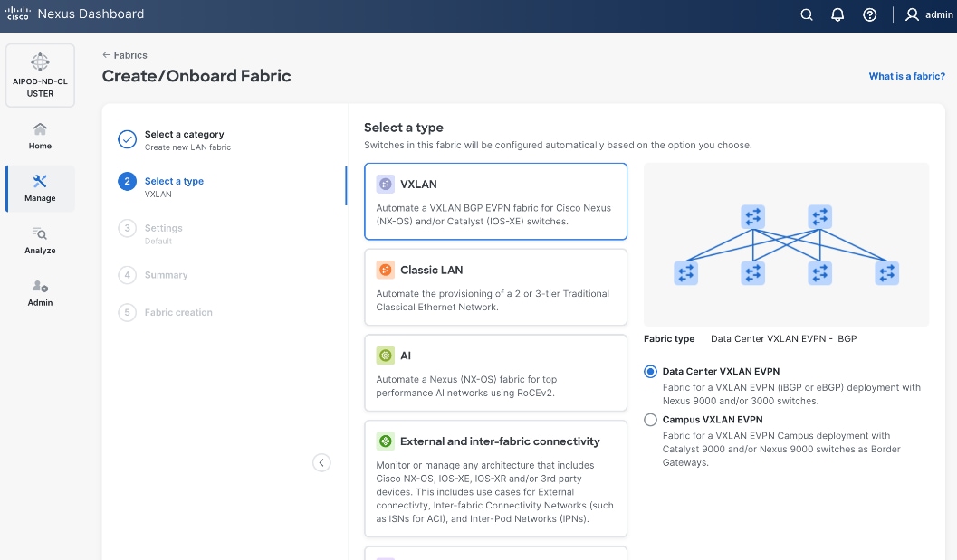
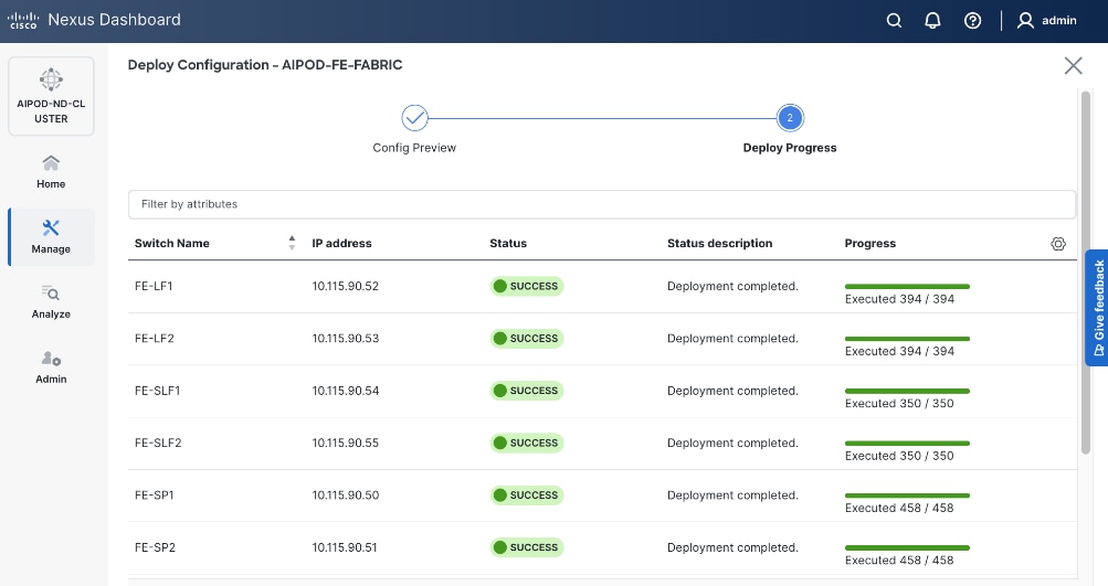
As with the backend fabric, the pre-built template enables the frontend fabric (two-spine, four-leaf) with ~400 lines of configuration (Figure 13) to be deployed in minutes.
Quality of Service (QoS), including PFC and ECN, was also deployed in this fabric to provide lossless connectivity for the RDMA traffic to Everpure FlashBlade//S. VLANs and overlays provide network isolation for the different traffic types traversing the fabric, but bandwidth fairness is achieved through the QoS policies deployed in the fabric. A dedicated queue is assigned to storage RDMA traffic to ensure consistent performance during data-intensive training. Similar to the backend, an MTU of 9216 is used for PFC and the bandwidth allocation is adjusted to ensure fair treatment.
The template deployed in the frontend does not include a QoS policy by default. For the CVD, a new QoS policy was created to reflect the 200GbE design used in this design. The new policy was created by duplicating an existing policy and making the necessary adjustments. Customers should review the available QoS policies and customize it as needed to meet the needs of their environments.
Everpure FlashBlade//S
The storage sub-system provides a unified platform for both file and object data protocols using Everpure FlashBlade. In this design, Everpure XFM-8400R2 modules serve as a storage aggregation layer, bundling individual links into a high-capacity 400GbE port-channel that connect to dedicated storage leaf switches in the frontend fabric. As storage demands grow, the scale-out architecture enables enterprises to incrementally scale their deployment, both by adding capacity within a FlashBlade//S system or by adding more systems as shown in Figure 14.
The NFS and object store traffic to and from Pure FlashBlade//S are segmented using different VLANs and trunked on the port channels from the XFMs to the storage leaf switches. NFS traffic uses a Layer 2 overlay while the S3 object store traffic uses a Layer 3 overlay across the frontend fabric.
Table 5. Everpure FlashBlade//S VLANs
| VLAN Name |
VLAN ID |
vPC ID |
L2VNI |
IP Subnet |
Purpose |
| OOB-MGMT |
550 |
N/A |
N/A |
10.115.90.14/26 (XFM-VIP) |
Pure One/Mgmt. Access |
| Pure-NFS_VLAN_3054 |
3054 |
19 |
33054 |
192.168.54.0/24 |
FE: NFS Storage Data |
| Pure-S3-OBJ_VLAN |
570 |
19 |
30570 |
10.115.90.208/29 |
FE: Object Store Data |
|
|
703 |
111-114 |
30703 |
10.115.90.64.0/26 |
FE: UCS C885A (Client side) |
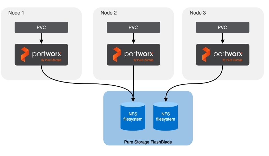
Portworx by Everpure provides persistent storage for the Kubernetes workloads in this design. It functions as a Container Storage Interface (CSI) plugin to enable dynamic storage provisioning for workloads running on OpenShift. The solution also includes a Kubernetes operator that automates deployment, configuration, and upgrades within the cluster.
For AI deployments, Portworx by Everpure is backed by NFS file systems running on Pure FlashBlade, as shown in Figure 15. The design utilizes the nconnect=16 mount option in the defined Storage Class, allowing the compute nodes to establish multiple parallel TCP sessions to the Everpure FlashBlade. This ensures the frontend uplinks are fully utilized during data-intensive training phases. Additionally, the Red Hat NMState Operator is deployed to provision the storage networking required to enable NFS storage access from the UCS worker nodes in the OpenShift cluster.
AI (Kubernetes) workloads running on the OpenShift cluster also have direct access to object stores deployed on Everpure FlashBlade//S. A dedicated network and interface is provisioned on the Everpure for this and the storage access traffic from these workloads will be routed to this network to access the S3 buckets.
A quick CLI based example of deploying and validating NFS using RDMA using Everpure FlashBlade//S is provided in the AI POD GitHub repo (see Everpure folder). The specifc deployment steps used in this CVD in provided in later sections.
Cisco UCS Compute
A Cisco UCS X-Series Direct system with three servers is deployed as control nodes for the OpenShift cluster. These servers are provisioned using a Server Profile Template in Cisco Intersight and deployed as bare-metal nodes using the Cisco Intersight integration in the Red Hat Assisted Installer workflow.
The initial configuration of these servers requires at least one network interface to be configured with the OpenShift cluster IP network VLAN to bring the cluster up. The necessary VLANs for control, management, and auxiliary services are trunked over the virtual port channel (vPC) to the Cisco UCS X-Series Direct chassis.
Once the cluster is operational, the Cisco UCS C885A GPU nodes are added as worker nodes. This is done as a follow-on step because these servers require different provisioning and networking configurations compared to the Cisco UCS X-Series servers. Also, unlike the GPU nodes, Cisco UCS X-Series server’s use:
● Server Profile Templates and Profiles in Cisco Intersight for initial configuration.
● Cisco Intersight integration within the Red Hat Assisted Installer for bare metal deployments.
Post-deployment, Cisco Intersight is used for ongoing operations and management of all servers.
Red Hat OpenShift
The OpenShift cluster is deployed using the recommended Red Hat Assisted Installer available via the Red Hat Hybrid Cloud Console, a SaaS-based service in the cloud. The installer requires DNS and DHCP services, and external connectivity to the Red Hat Hybrid Cloud Console to be in place before the installation can start. An OpenShift Installer workstation (any Linux distribution) is also required to deploy and manage the cluster.
Three servers in the Cisco UCS X-Series Direct are deployed as a highly available control plane for the OpenShift cluster. The OpenShift cluster is implemented as a compact cluster, allowing the Cisco UCS X-Series servers to also function as worker nodes to host other services and workloads. In this design, these servers host secondary DHCP and DNS services by leveraging OpenShift Virtualization. The design and deployment of OpenShift Virtualization is outside the scope of this document.
As stated earlier, the UCS GPU nodes are added as worker nodes to the same OpenShift cluster. The networking connectivity to the frontend fabric is provisioned at install time. The remaining configuration is done using OpenShift operators once the cluster is up and running with GPU worker nodes. All required operators are available via the Red Hat Operator Hub and are directly accessible from the OpenShift cluster console. The following operators are used to provision the GPU worker nodes in this design.
● Red Hat Node Feature Discovery (NFD) Operator is responsible for discovering and exposing the hardware capabilities of the NVIDIA GPUs and NICs in the UCS worker nodes. NFD labels the nodes with hardware-specific information (for example, PCI vendor code, CUDA capabilities, kernel version), enabling NVIDIA GPU and Network operators to deploy and configure the devices accordingly. The NFD operator detects and labels the NVIDIA NIC and GPU as shown. Multiple labels are added for a given hardware, but the presence of a NVIDIA GPU and NIC is indicated by the following labels:
◦ feature.node.kubernetes.io/pci-10de.present=true (GPU)
◦ feature.node.kubernetes.io/pci-15b3.present=true (NIC)
● Red Hat NMState Operator provides a declarative, Kubernetes-native way to manage node-level networking across the OpenShift cluster. Instead of manually configuring each server, you define the desired network state (such as IP addresses, MTU, and interface bonding) through a Kubernetes API. For this CVD, the NMState operator is used to adding storage interfaces with VLAN trunking, changing MTU to support jumbo frames etc. By using this operator, the network configuration becomes part of the cluster's desired state and by applying it to all worker nodes (for example) makes it easier to scale the AI POD by automatically applying the correct settings to new nodes as added.
● Portworx Enterprise by Everpure Operator provides persistent storage for Kubernetes’ workloads within the Cisco AI POD. It functions as a CSI plugin to enable dynamic storage provisioning and management for AI pipelines running on Red Hat OpenShift. The operator automates the deployment, simplifying the lifecycle management of the storage environment as the cluster scales. Portworx also provides a dashboard that is directly accessible from the OpenShift cluster console to manage the environment.
● NVIDIA Network Operator automates the provisioning of high-performance networking for the NVIDIA NICs in the UCS GPU nodes. By managing the installation of necessary drivers and libraries, such as MOFED, it enables low-latency communication between GPUs. The associated Network Cluster Policy is used to enable GPUDirect RDMA and GPUDirect Storage (GDS), ensuring the backend fabric is optimized for high-bandwidth AI workloads.
● NVDIA GPU Operator simplifies the management of NVIDIA GPUs by automating the installation of drivers, the container toolkit, and monitoring tools. It ensures that GPU resources are correctly exposed to the OpenShift scheduler and ready for AI tasks. The associated GPU Cluster Policy works in conjunction with the Network Operator to enable GPUDirect RDMA and GPUDirect Storage, allowing for direct data transfers between GPU memory and the network.
● Red Hat OpenShift AI Operator is used to deploy and enable a comprehensive MLOps environment for the cluster. It manages the full lifecycle of AI workloads—from model development and training to serving—and coordinates with additional operators to provide a seamless, end-to-end AI pipeline.
Deploying the NVIDIA Network Operator with a cluster policy enabled for RDMA will cause new drivers to be loaded on all NVIDIA NICs in the node, including the frontend NIC used as the OpenShift Cluster IP, resulting in a temporary outage during this time. It is recommended that you deploy a jump host with direct access to the cluster via Intel OCP NICs on the Cisco UCS C885A servers to ensure backup access to the cluster in the event of a problem.
The AI POD design implements GPUDirect RDMA to accelerate distributed training and fine-tuning across the backend fabric and GPUDirect Storage for high-speed storage access via the frontend fabric. While this can be deployed using various methods, this CVD uses a multi-tenant approach that allows multiple pods on the same worker node to share the RDMA device (NIC). Specifically, a MacvlanNetwork Custom Resource Definition (CRD) is used to provision IP addressing and enable network access across the shared physical network interface for both the backend and frontend fabrics to support GPUDirect RDMA and GPUDirect Storage, respectively.
The Layer 2 (overlay) connectivity used for inter-node GPU communication between the 4 Cisco UCS C88A M8 nodes in the backend fabric also requires the following changes to be implemented on node.
Solution Deployment
This section details the deployment of the specific AI POD design discussed in the previous section, based on validation in Cisco labs. This chapter contains the following:
Deploy Frontend Fabric using Nexus Dashboard
Deploy Backend Fabric using Nexus Dashboard
Deploy NFS Storage on Everpure FlashBlade
Deploy Object Store on Everpure FlashBlade
Deploy UCS Management Nodes from Cisco Intersight
Deploy Red Hat OpenShift on UCS Servers
Initial Setup of Cisco UCS C885A GPU Servers
Add Cisco UCS C885A GPU Servers to OpenShift Cluster
Set up Networking for Storage Access
Deploy Portworx to provide Persistent Storage
Set up Portworx for NFS over TCP Access to Storage
Deploy GPUDirect RDMA on Backend Fabric
Set up Portworx for NFS over RDMA Access to Storage
Set up Portworx for GPUDirect Storage
Deploy Red Hat OpenShift AI for MLOps
This section provides a high-level overview of the steps involved in deploying the end-to-end solution. The sections that follow will provide the detailed procedures for each step. A summary view of these implementation steps are provided in Table 6.
| Steps |
Deployment Action |
| CVD_01 |
Deploy a 3-node Nexus Dashboard (ND) Cluster
● Set up the first node in a 3-node Nexus Dashboard cluster
● Use the cluster bring up workflow to (1) complete the setup of the first node, (2) deploy remaining nodes in the cluster and (3) bring up the 3-node ND cluster.
|
| CVD_02 |
Deploy Frontend (FE) Network Fabric
● Use Nexus Dashboard blueprint/template to deploy a VXLAN EVPN Fabric on the FE switches connected in a 2-tier Spine-Leaf topology
● Enable Virtual Port-Channel (vPC) peering on Compute/Management leaf pairs in FE fabric.
● Enable vPC peering on Storage Leaf switch pairs to connect to Everpure XFM modules
● Enable Layer 2 Connectivity to Management UCS X-Direct from FE fabric
● Enable Layer 2 Connectivity to UCS GPU Nodes from FE Fabric
● Enable IB-MGMT Connectivity for Cisco UCS (GPU + Management) Nodes
● Enable Layer 2 Connectivity to Everpure FlashBlade//S from FE Fabric
● Enable NFS Storage Data Access to Everpure FlashBlade//S
● Enable S3-compatible Object Store Data Access to Everpure FlashBlade//S
● Enable external connectivity from the FE fabric to access SaaS services (Cisco Intersight, Red Hat Hybrid Cloud Console) and other services outside this fabric
● Enable QoS for storage RDMA traffic in the FE fabric
|
| CVD_03 |
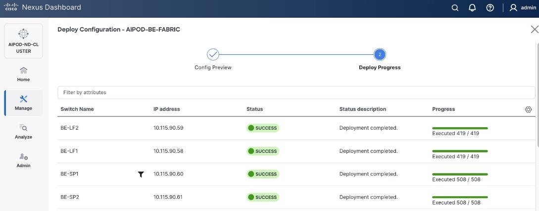
Deploy Backend (BE) Network Fabric
● Use Nexus Dashboard blueprint/template to deploy a VXLAN EVPN Fabric on the BE switches connected in a 2-tier Spine-Leaf topology
● Enable QoS for inter-node GPU-to-GPU RDMA traffic in the BE fabric
● Enable GPU-to-GPU networking between UCS GPU nodes across the BE fabric using a Layer 2 overlay
|
| CVD_04 |
Deploy NFS Storage on Everpure FlashBlade//S
● Prepare Hardware: Coordinate site power/cooling and complete the Installation Workbook to define your network parameters.
● Configure Networking: Log into the FlashBlade CLI or portal to create the required subnets and two specific DataVIPs for pod connectivity.
● Provision NFS Storage: Create the filesystem with your desired capacity and enable the NFSv3 protocol.
● Route and Mount: Verify routing from compute nodes to storage using the NFS data interface. Mount the filesystem using NFS over RDMA with aggregate mount options.
● Validate Installation: Run the
mountmount command on compute nodes to confirm the filesystem is active with the correct RDMA and
nconnectnconnect settings.
|
| CVD_05 |
Deploy S3-compatible Object Store on Everpure FlashBlade//S
● Configure Networking: Log into the FlashBlade CLI or portal to create the required subnets and specific DataVIPs for pod connectivity.
● Provision Object Store: Create an account and quota for the account. Create user, access policies, S3 buckets and access key to access the S3 buckets.
● Route: Verify routing from compute nodes to storage using the S3 Object data interface. Deploy workload to verify access.
|
| CVD_06 |
Deploy UCS Management Servers from Cisco Intersight
● Create Server Profile Template for UCS servers for use as OpenShift control (optionally as worker nodes) in the OpenShift cluster with Cisco UCS C885A GPU nodes. Servers should have at least one interface provisioned in the cluster management network (same as in-band management in this deployment).
● Deploy server profile to provision a minimum of 3 servers to provide high availability.
|
| CVD_07 |
Deploy Red Hat OpenShift on Bare Metal UCS Management Servers
● Setup prerequisites for deploying the cluster such as setting up an installer workstation, DNS, DHCP and so on.
◦ Deploy an installer machine to remotely manage the OpenShift cluster and to serve as an HTTP server to load OpenShift images on Cisco UCS C885 servers (later). Generate public SSH keys on the installer to enable SSH access to OpenShift cluster post-install.
◦ Add DNS records for cluster API and Ingress Virtual IP (VIP)
◦ Add DHCP pool for OpenShift cluster nodes to use. Configure DHCP options for NTP, Gateway (for routed subnets) and DNS.
● Deploy OpenShift cluster using Assisted Installer workflow from Red Hat Hybrid Cloud Console (console.redhat.com). Use Cisco Intersight integration to seamlessly discover and deploy OpenShift on bare metal UCS management/control nodes.
● Complete post-deployment setup
◦ Save installation files - kubeconfig and kubeadmin password
◦ Download oc tools
◦ Setup power management for the UCS bare metal hosts in the newly deployed cluster
◦ Reserve resources for system components on control and worker nodes
◦ Setup NTP on control and worker nodes
◦ Setup a second administrative user (htpasswd used in this setup)
|
| CVD_08 |
Initial Setup of Cisco UCS C885A GPU Servers
● Configure NTP, DNS, Security policies, BIOS settings and other basic setup on Cisco UCS via Cisco BMC.
● Setup Intersight Management – Claim and add UCS C885A nodes in Cisco Intersight.
● Collect MAC addresses of the frontend NIC from all UCS C885A Nodes. The first port will be provisioned as the cluster IP network in OpenShift. You can collect this from Intersight or via Cisco BMC.
● Create DHCP reservations for the mac addresses collected above.
● Create DNS records for the reserved DHCP IP addresses.
● Setup/Verify that the BlueField-3 NICs are in NIC mode (vs. DPU mode).
● Setup/Verify that the NVIDIA CX-7 cards are in Ethernet mode (vs. InfiniBand/IB).
● Create machine configuration files on installer VM. UCS C885A will require a Bare Metal Host (BMH) config. file using the above frontend NIC MAC address.
● Verify Redfish access to the UCS-C885A.
● Upgrade to latest firmware for all components on the UCS C885A. Use Cisco UCS Hardware Compatibility (HCL) tool and Intersight HCL check to confirm the latest version is deployed on the node.
|
| CVD_09 |
Add Cisco UCS C885A nodes to the OpenShift cluster from Red Hat Hybrid Cloud Console
● Networking configuration for UCS C885A worker nodes is specified using
Static IP, bridges and bondsStatic IP, bridges and bonds option in the Assisted Installer. The two ports on the FE NIC are configured as an LACP bond with the OpenShift Cluster IP VLAN added as trunked VLAN to this bond. You will need the mac address of both FE interfaces collected earlier.
● Set up UCS server as a bare metal host from OpenShift cluster console (or via CLI from OpenShift Installer machine)
● Provision power management for UCS C885A using Redfish
|
| CVD_10 |
Set up Networking for Storage Access using NFS
● Deploy Red Hat Kubernetes NMState Operator
● Configure UCS worker node(s) for NFS storage access
● Verify the connectivity to Everpure FlashBlade using NFS network
|
| CVD_11 |
Deploy persistent storage using Portworx by Everpure
● Create API token on Everpure FlashBlade for use by Portworx
● Deploy Kubernetes secret to securely access Everpure FlashBlade
● Generate Portworx Enterprise Specification from Portworx Central
● Deploy Portworx Enterprise Operator from Red Hat OpenShift Cluster Console
● Verify that Portworx cluster is up and running in OpenShift
|
| CVD_12 |
Setup Portworx for NFS over TCP access to storage
● Create Storage Class for NFS over TCP to Everpure FlashBlade
● Provision the newly created storage classes as the default storage class (Optional)
● Create a Persistent Volume Claim to verify setup
|
| CVD_13 |
Deploy NVIDIA GPU Operator in Red Hat OpenShift
● Deploy Red Hat Feature Discovery Operator. Verify that the worker nodes with GPUs are identified and labelled. Label should be (
pcie-10de.present=truepcie-10de.present=true)
● Deploy NVIDA GPU Operator
● Enable Data Center GPU Monitoring (DCGM) dashboard in OpenShift cluster console:
https://docs.nvidia.com/datacenter/cloud-native/openshift/latest/enable-gpu-monitoring-dashboard.htmlhttps://docs.nvidia.com/datacenter/cloud-native/openshift/latest/enable-gpu-monitoring-dashboard.html
● Set up taints on worker nodes and tolerations on workloads (or Pods)
|
| CVD_14 |
Deploy GPUDirect RDMA on Backend Fabric
● Log into
intersight.com and collect MAC Addresses for all E-W and N-S NICs and interface names for the C885As.
● Create and apply unique node label to UCS C885A nodes
● Create a new machine config pool with only UCS C885 GPU nodes
● Create persistent Interface Naming for all NVIDIA NICs
● Verify that NVIDIA network devices are present and labelled
● Create password for core user to access node
● Disable IRDMA and RPCRDMA Kernel Modules
● Deploy NVIDIA Network Operator from Red Hat Cluster Console
● Configure NIC Cluster Policy for NVIDIA Network Operator
● Set MTU to 9000 on NVIDIA backend NICs
● Create MAC VLAN Network to provision backend interfaces
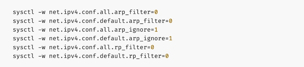
● Deploy ARP and RP policies
● Update GPU Cluster Policy
Note: If you run into issues with NIC Cluster policy coming up, you may need to put Portworx into maintenance mode and/or remove GPU operator.
|
| CVD_15 |
Validate GPUDirect RDMA
● Deploy workload to test and verify GPUDirect RDMA
● Use
IB_WRITE IB_WRITE tests to validate RDMA traffic across backend fabric
● Use
NCCL NCCL tests to validate inter-node GPU-to-GPU RDMA traffic across backend fabric
|
| CVD_16 |
Setup Portworx for NFS over RDMA access to storage
● Provision Kubernetes storage class to use NFS over RDMA with Portworx, backed by FlashBlade
● Put Portworx in maintenance mode
● Remove previously deployed NVIDIA GPU operator(if present)
● Update NVIDIA NIC Cluster policy to use RDMA
● Deploy GPU Operator and Cluster Policy
● Take Portworx out of maintenance mode
● Validate NFS over RDMA to Everpure
Note: Unlike deployment steps for “Deploy GPUDirect RDMA on Backend Fabric” earlier, the above procedures put Portworx in maintenance mode and removes GPU cluster policy before NIC cluster policy update.
|
| CVD_17 |
Setup Portworx for GPUDirect Storage
● Provision Kubernetes storage class to use NFS over RDMA with Portworx, backed by FlashBlade
● Put Portworx in maintenance mode
● Remove previously deployed NVIDIA GPU operator(if present)
● Update NVIDIA NIC Cluster policy to use RDMA
● Deploy GPU Operator and Cluster Policy
● Take Portworx out of maintenance mode
● Validate GPUDirect Storage to Everpure
Note: Unlike deployment steps for “Deploy GPUDirect RDMA on Backend Fabric” earlier, the above procedures put Portworx in maintenance mode and removes GPU cluster policy before NIC cluster policy update. Deploy GPU Cluster Policy
|
| CVD_18 |
Deploy Red Hat OpenShift AI for MLOps
● Add users and administrator groups in OpenShift to enable for access to OpenShift AI web UI.
● Deploy Persistent storage for AI/ML efforts. In this solution, the ML engineer’s work (image, environment) is saved on persistent volumes, backed by Everpure FlashBlade.
● Deploy S3-compatible object store. In this CVD, it used as model repository and to store pipeline artifacts on Everpure FlashBlade
● Deploy prerequisite operators for OpenShift AI - Service Mesh Operator, Red Hat OpenShift Serverless, Red Hat Authorino
● Deploy Red Hat OpenShift AI Operator. The environment is now ready for accelerating and operationalizing enterprise AI/ML efforts at scale.
● Modify Storage Classes for persistent storage – enable ReadWriteMany for training and fine-tuning workloads
|
| CVD_19 |
Validate solution using fine-tuning workload in OpenShift AI
● Setup workbench for the workload in OpenShift AI
● Setup GitHub access from workbench and deploy workload
● Monitor GPU utilization
|
| CVD_20 |
Validation summary
● GPU Functional Validation – Sample CUDA Application
● GPU Burn Test:
https://github.com/wilicc/gpu-burn
● IB_WRITE Tests
● NCCL Tests
● MLPerf
|
The procedures detailed in this section explain how to deploy a 3-node Nexus Dashboard (ND) cluster. The Cisco Nexus Dashboard provided templates are used to deploy both the backend and frontend fabrics in the AI POD solution.
The procedures in this section will:
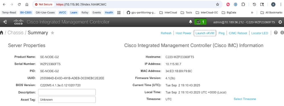
● Setup the first node in a 3-node Nexus Dashboard Cluster using CIMC management.
● Use the web UI and cluster bring up workflow to complete the setup of the first node, deploy remaining nodes in the cluster and bring up the 3-node ND cluster.
Assumptions and Prerequisites
● Out-of-band/CIMC access to the first Nexus Dashboard node in the cluster.
● Access to Nexus Dashboard ISO image on a local or remote (NFS/HTTP) server.
● DNS and NTP services are available for use by Nexus Dashboard cluster
Setup Information
Table 7. Setup Parameters for Nexus Dashboard
| Parameter Type |
Parameter Name | Value |
Additional Information |
| Nexus Dashboard Management |
ND-MGMT |
|
| CIMC IP for first ND (ND-1) |
10.115.90.7/26 |
|
| ND-MGMT IP for first ND |
10.115.90.21/26 |
|
| Gateway IP |
10.115.90.1/26 |
|
| Cluster Bringup Workflow |
||
| Basic Information |
|
|
| Cluster Name |
AIPOD-ND-CLUSTER |
|
| Implementation Type |
LAN (default) |
|
| Configuration |
|
|
| DNS Server |
64.102.6.247 |
|
| DNS Search Domain |
cisco.com |
|
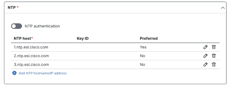
| NTP |
1.ntp.esl.cisco.com 2.ntp.esl.cisco.com 3.ntp.esl.cisco.com |
Add at least two NTP sources for redundancy |
| Proxy |
Skip Proxy |
|
| Advanced Settings |
<Using defaults> |
|
| Node Details: ND-1 |
|
|
| General |
|
|
| Hostname |
ND-1 |
First ND Node |
| Type |
Primary |
|
| Management Network |
|
|
| IP Address |
<Same as ND-MGMT > |
Provided above |
| Gateway |
<Same as ND-MGMT> |
Provided above |
| Data Network |
|
|
| ND-DATA: IP for ND-1 |
10.115.90.225/27 |
|
| ND-DATA: Gateway |
10.115.90.254 |
|
| Node Details: ND-2 |
|
|
| CIMC IP |
10.115.90.8 |
Second ND Node |
| Username |
admin |
|
| Password |
<specify> |
|
| General |
|
|
| Hostname |
ND-2 |
|
| Type |
Primary |
|
| Management Network |
|
|
| IP Address |
10.115.90.22/26 |
|
| Gateway |
10.115.90.1 |
|
| Data Network |
|
|
| ND-DATA: IP for ND-2 |
10.115.90.226/27 |
|
| ND-DATA: Gateway |
10.115.90.254 |
|
| Node Details: ND-3 |
|
|
| CIMC IP |
10.115.90.9 |
Third ND Node |
| Username |
admin |
|
| Password |
<specify> |
|
| General |
|
|
| Hostname |
ND-3 |
|
| Type |
Primary |
|
| Management Network |
|
|
| IP Address |
10.115.90.23/26 |
|
| Gateway |
10.115.90.1 |
|
| Data Network |
|
|
| ND-DATA: IP for ND-3 |
10.115.90.227/27 |
|
| ND-DATA: Gateway |
10.115.90.254 |
|
|
|
|
|
| Persistent IPs |
10.115.90.228-.238 |
|
Deployment Steps
To deploy a 3-node Nexus Dashboard cluster, complete the procedures below using the setup information provided in this section.
Bring up first node in a 3-node Nexus Dashboard cluster
Procedure 1. Deploy first Nexus Dashboard cluster node
Step 1. SSH into the first node:
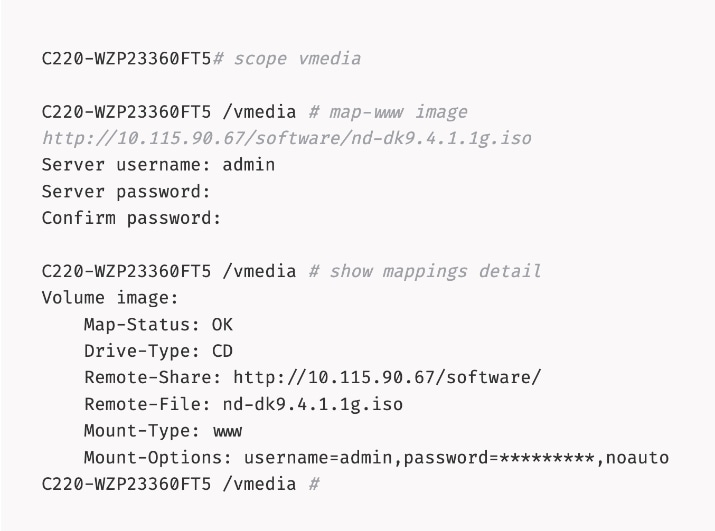
Step 2. Mount the Nexus Dashboard ISO from a HTTP server using remote vMedia:
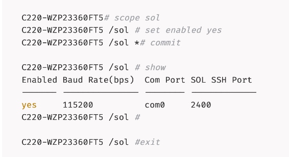
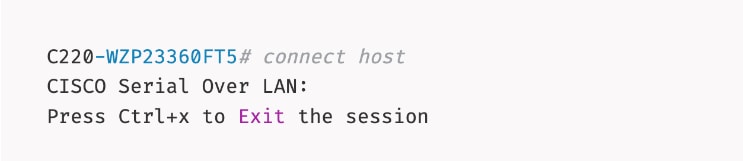
Step 3. Connect to Host over Serial Over LAN or go to next step and using vKVM from a browser.
Step 4. From a browser, go back to CIMC of the node and open the vKVM console.
Step 5. Click Launch vKVM from the top menu. In the newly opened vKVM viewer window, click Reset System.
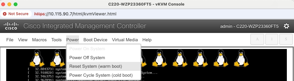
Step 6. Click OK in the next pop-up window.
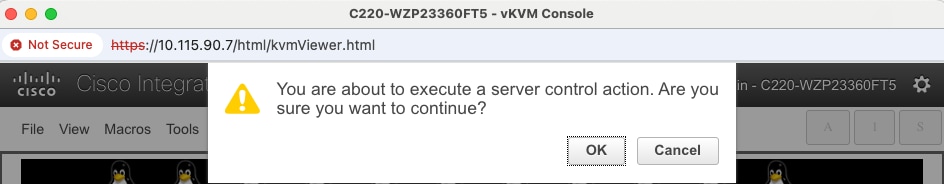
Step 7. Monitor the booting process.
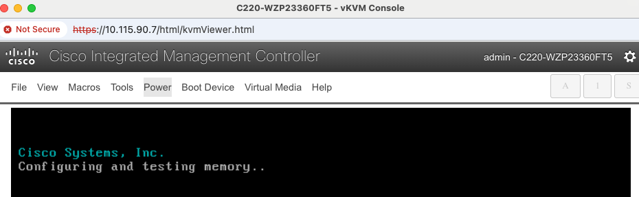
Step 8. Go to Macros to define the User Defined Macros for F6.
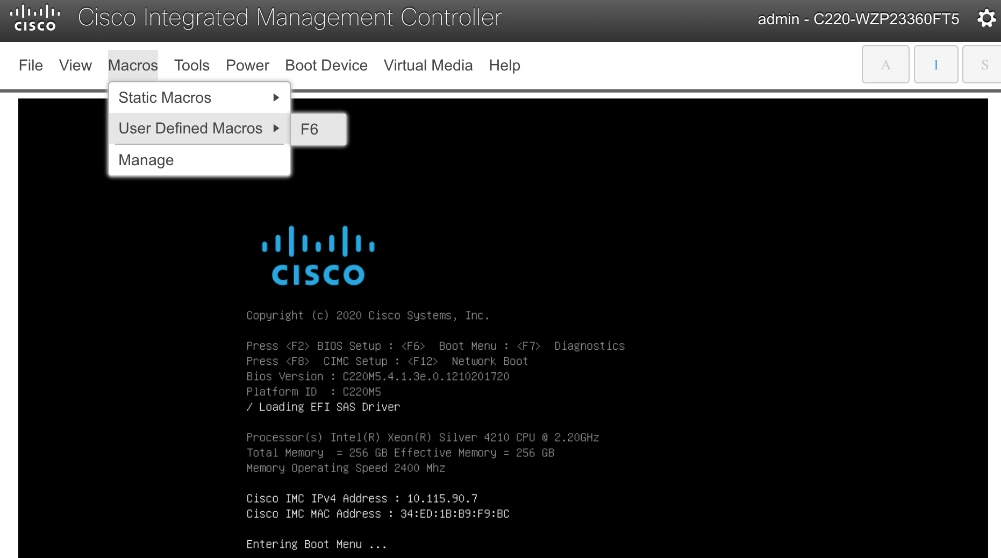
Step 9. Click F6 to bring up the boot menu when you see Entering Boot Menu in vKVM.

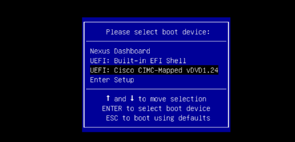
Step 10. Use Up/Down arrow keys to select UEFI: Cisco CIMC-Mapped vDVD as the boot device from the boot menu.
Step 11. Wait until you see the message to login to Serial Over LAN (SOL) console.
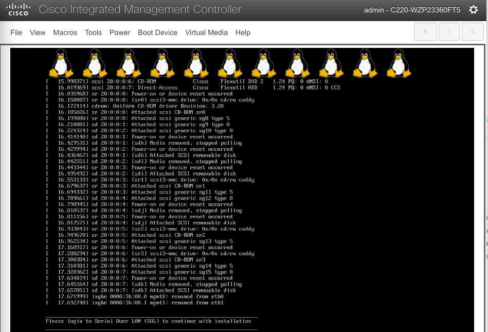
Step 12. Switchback to the SSH terminal session and you should see the following messages on the host console:
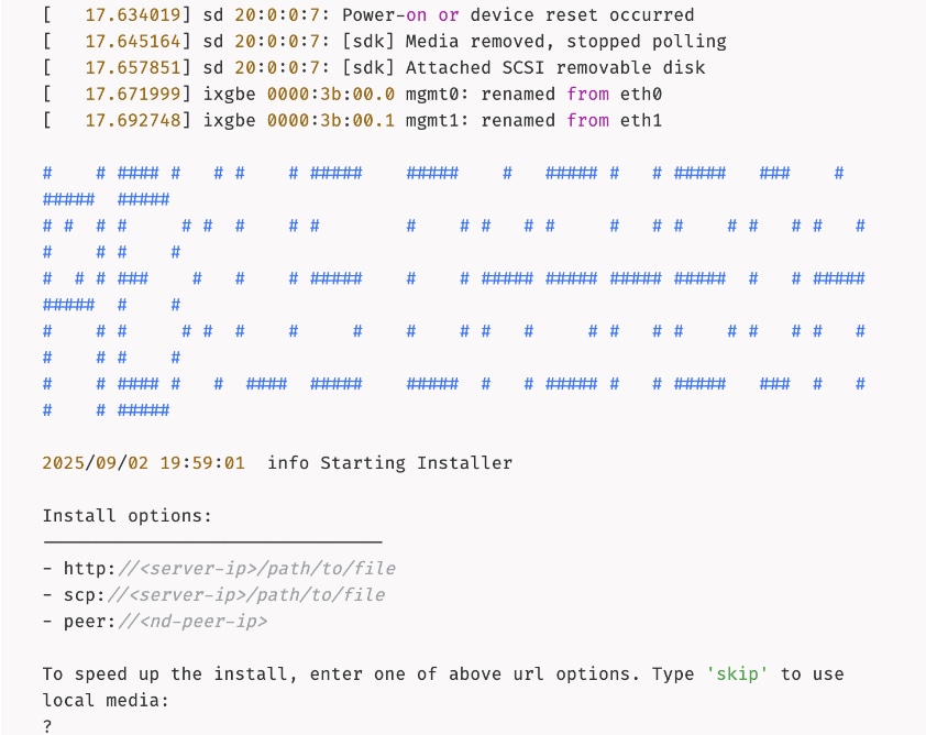
Step 13. Type skip to use the previously CIMC-mounted vMedia image.
Step 14. Once the installation completes successfully, the node will be powered off. Unmount the vMedia and power on the host.
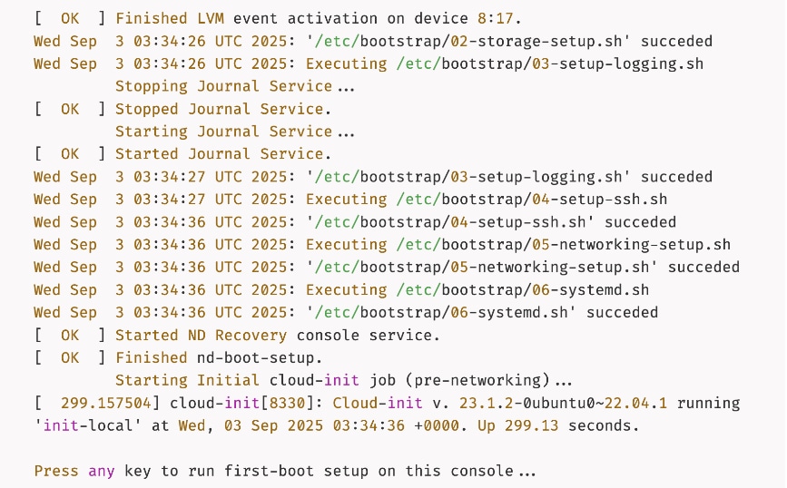
Step 15. Press any key to run first-boot setup.
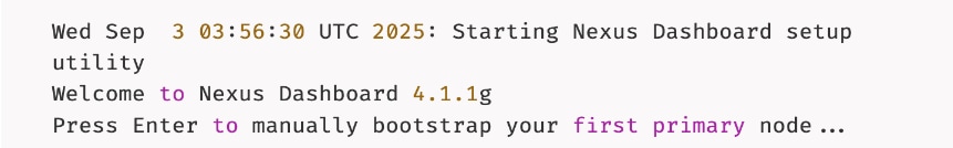
Step 16. Press Enter to manually bootstrap your first primary node...
Step 17. Specify admin password, IP Address/Mask for Management Network, and Gateway.
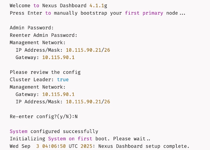
Step 18. Wait for the setup to complete and you see the following message on the console.
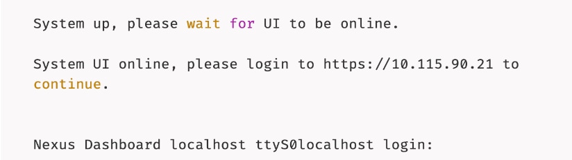
Complete Deployment and Setup of Nexus Dashboard Cluster using Workflow
Procedure 1. Install and setup remaining nodes and bring up Nexus Dashboard cluster
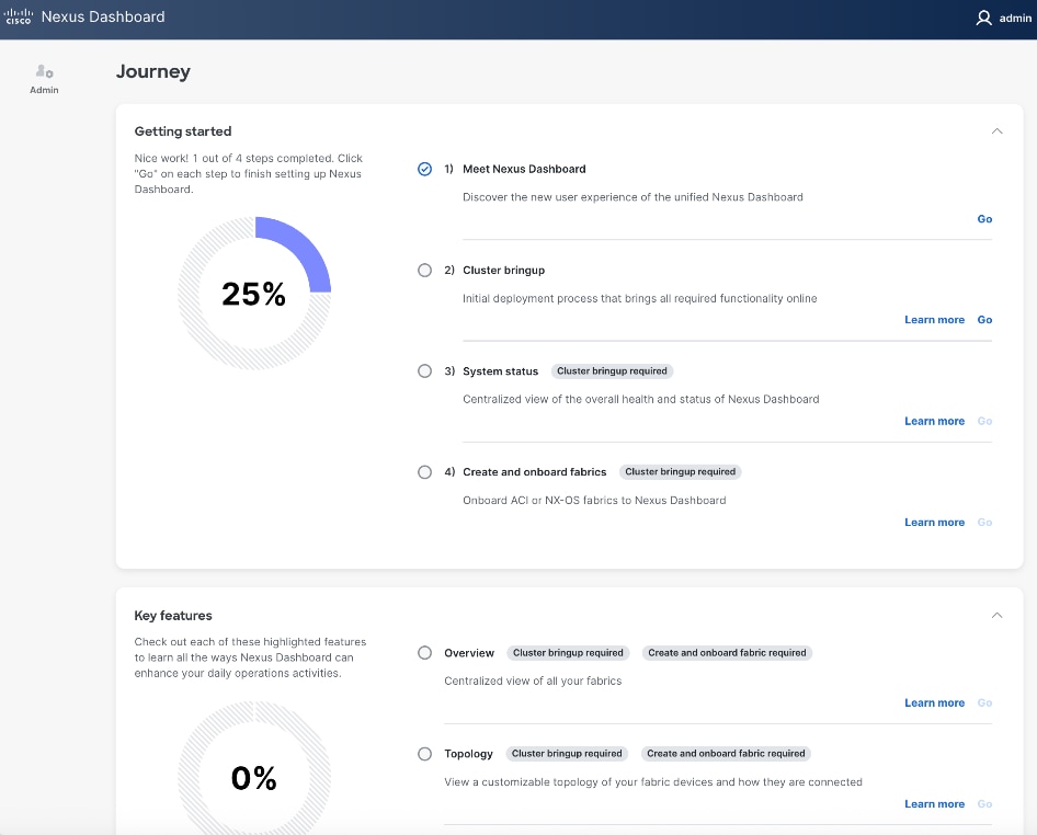
Step 1. From a browser, go to the management IP of the Nexus Dashboard. Log in using admin account.
Step 2. Cancel the pop-up windows titled Meet Nexus Dashboard. You should be redirected to the initial setup wizard or Journey screen.
Step 3. From Cluster bringup, click Go.
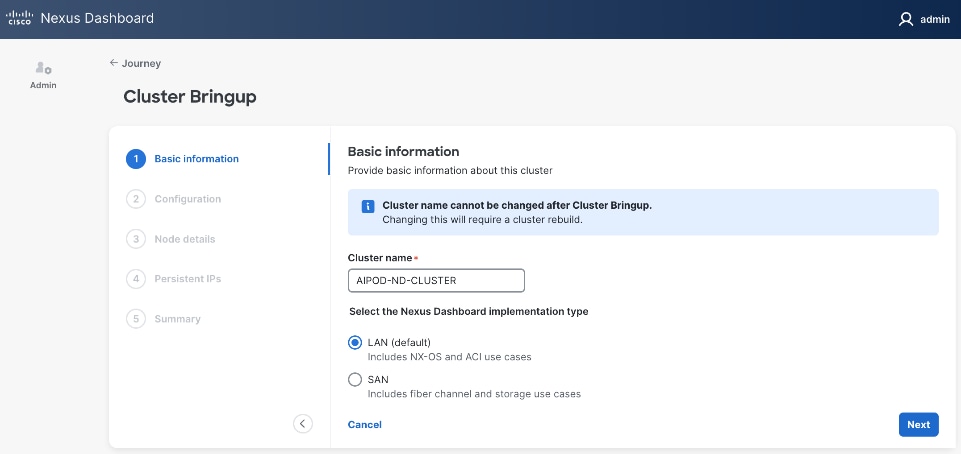
Step 4. In the Cluster Bringup workflow, for Basic Information, specify a Cluster Name and select radio button for LAN (Default). Click Next.
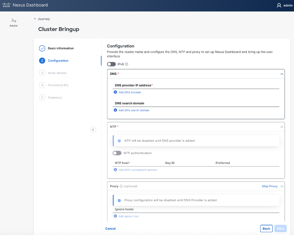
Step 5. In the Cluster Bringup workflow, for Configuration, for DNS, click Add DNS provider and specify a DNS Server IP.
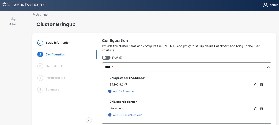
Step 6. (Optional) Repeat this step to add multiple DNS servers.
Step 7. (Optional) Add DNS search domain.
Step 8. For NTP, click Add NTP hostname/IP address and specify NTP server IP or hostname.
Step 9. (Optional) Repeat this step to add multiple NTP servers. Minimum of two NTP servers are recommended. Click the checkbox to select one as Preferred.
Step 10. (Optional) For Proxy, provide Proxy server information. Otherwise, click Skip Proxy in the section and click Confirm in the pop-up warning message.
Step 11. (Optional) For Advanced Settings, expand Advanced settings to specify App/Service subnets from the default settings (not recommended).
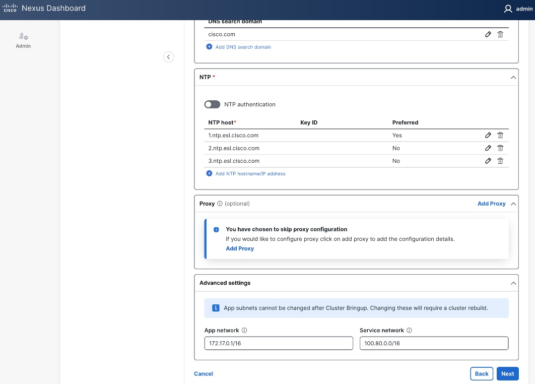
Step 12. Click Next.
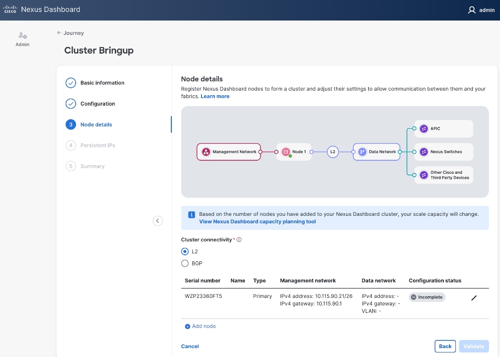
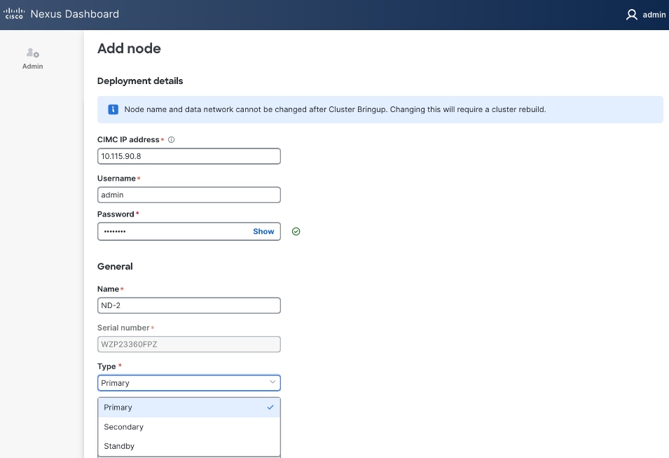
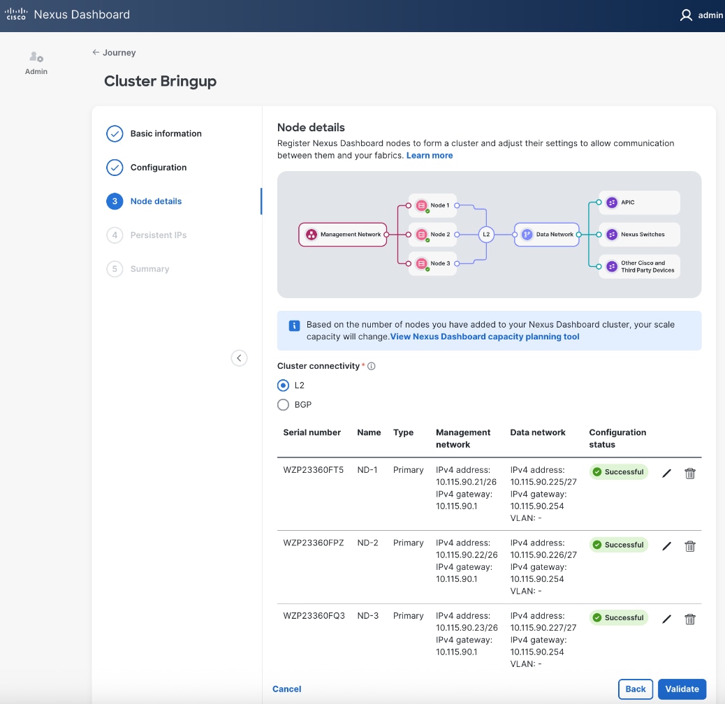
Step 13. In the Cluster Bringup workflow, for Node Details, click Incomplete to the right of the serial number for the first primary ND node to complete the setup.
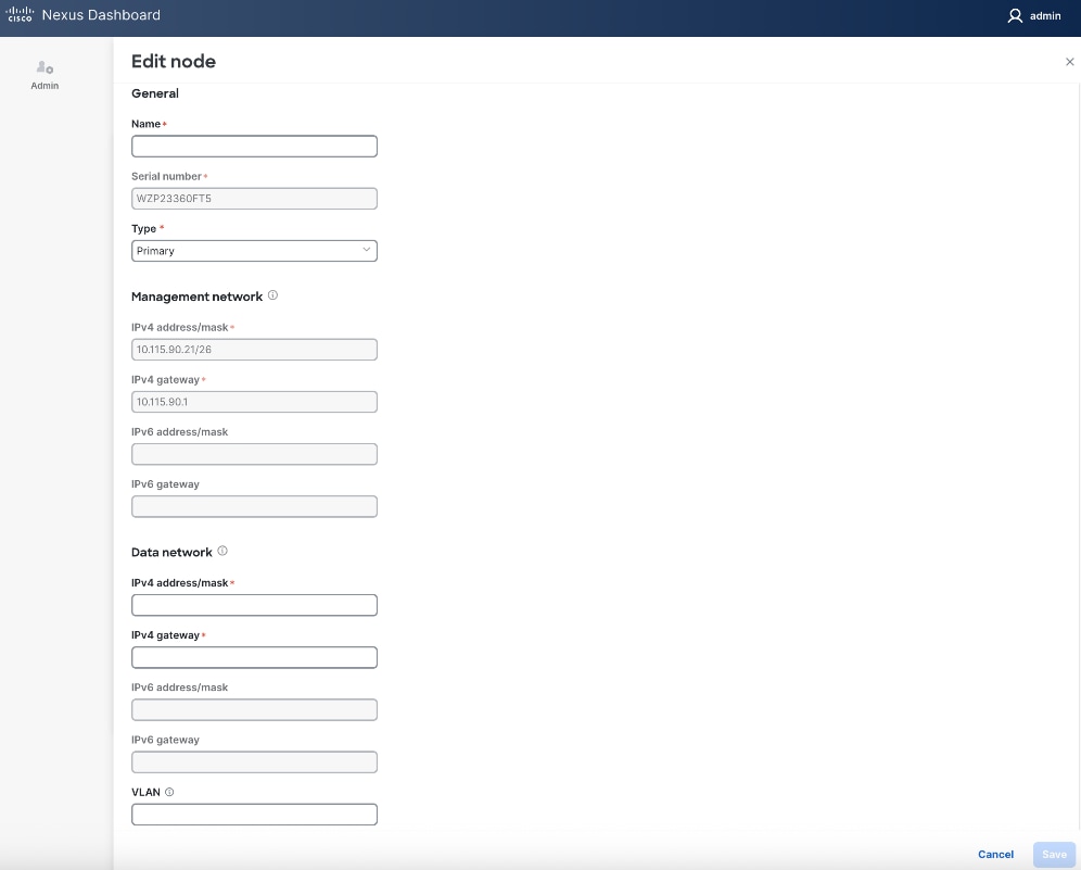
Step 14. In the Edit node window, specify hostname for first ND. Leave Type as Primary. Everything else should already be filled in under General and Management network sections below it.
![]()
Step 15. Scroll down to Data network section. Specify IP address/mask and gateway info for the data network.
Step 16. (Optional) specify a VLAN ID if you're not using a native VLAN on the link towards the fabric. If a VLAN is specified, the fabric facing links/ports on the ND node and switch it connects to will need to be configured for trunking.
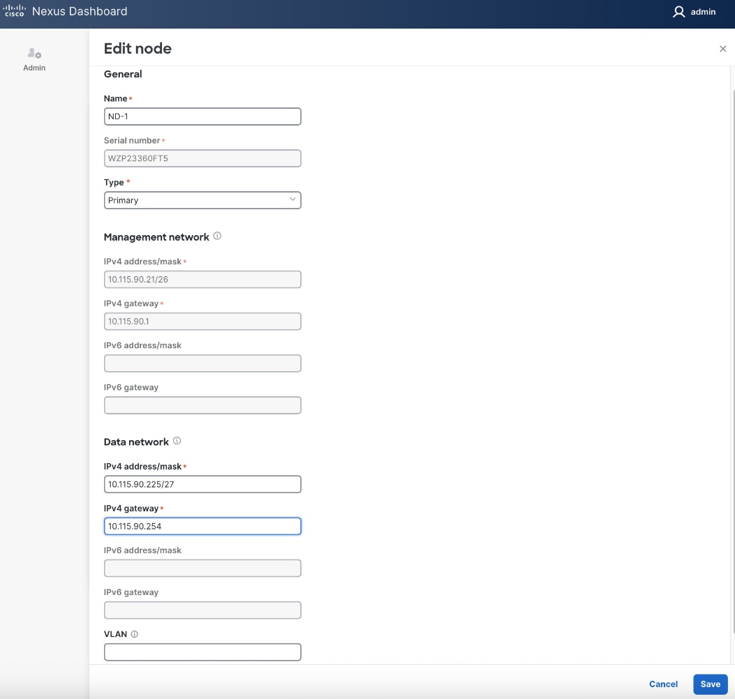
Step 17. Click Save.
Step 18. Click Add Node to add a second Primary node to the cluster.
Step 19. In the Add node window, specify CIMC (IP address, Access info). Click Validate.
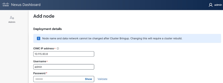
Step 20. If the CIMC verification succeeds, after a couple of minutes, remaining fields in the Add node window will become available.
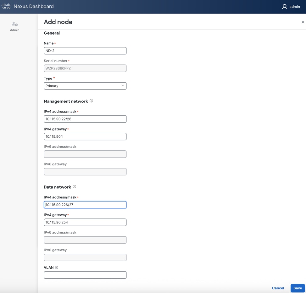
Step 21. For Name, specify hostname for second ND node. For Type, select Primary from the drop-down list.
![]()
Step 22. For the Management network and Data network, specify IP address/mask, gateway info for the second ND node.
Step 23. Click Save.
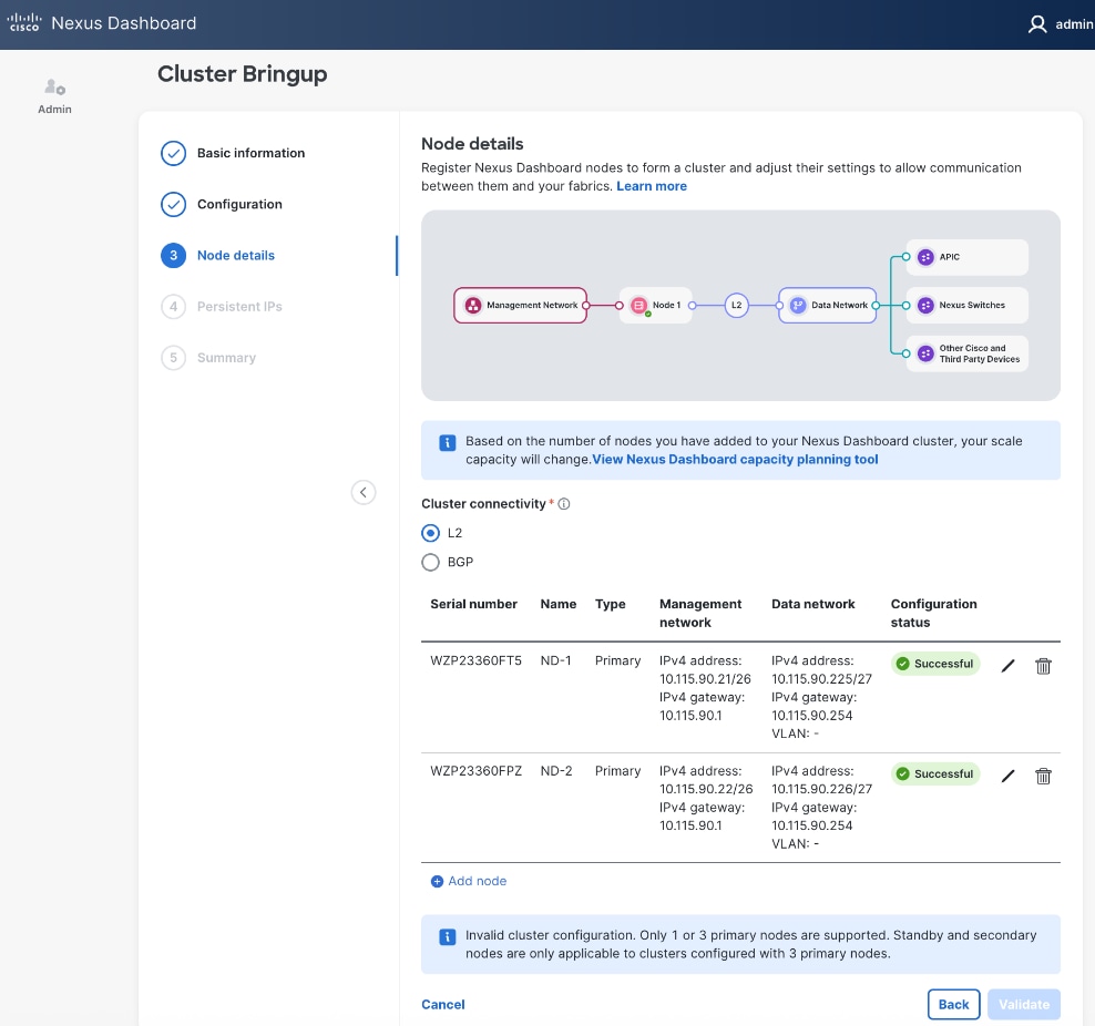
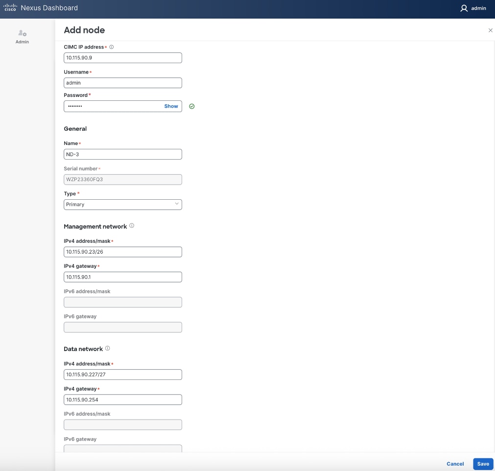
Step 24. Repeat steps 1 – 23 for second ND Node to add a third primary node to ND cluster.
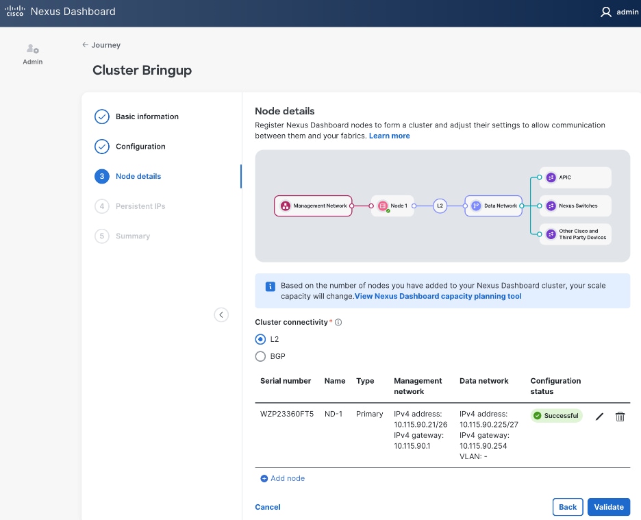
![]()
Step 25. Click Save.
Step 26. Click Validate.
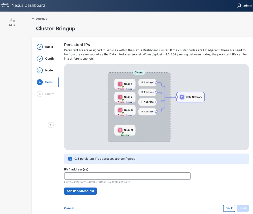
Step 27. Specify Persistent IPs - one by one or a range. Minimum of 5 must be provided. In L2 mode, they must be from the same subnet as ND Data Network subnet.
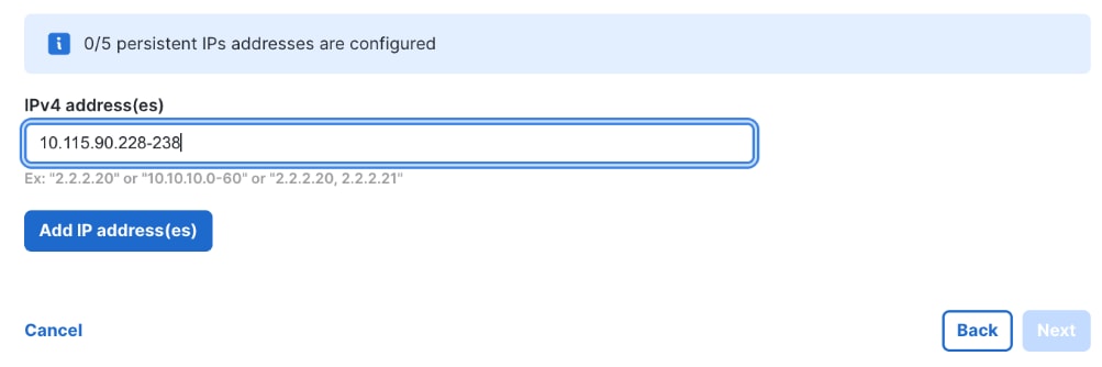
Step 28. Click Add IP address(es).
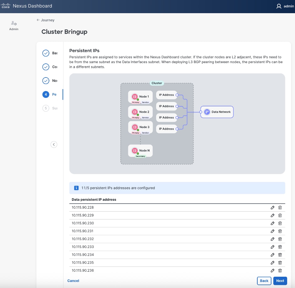
Step 29. Click Next.
Step 30. In the Summary view, expand each section and verify all settings.
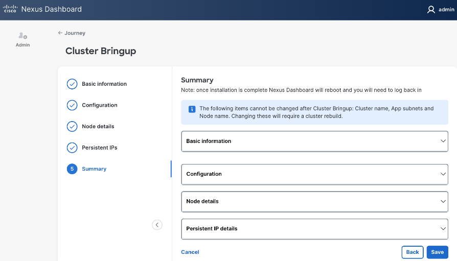
Step 31. Click Save.
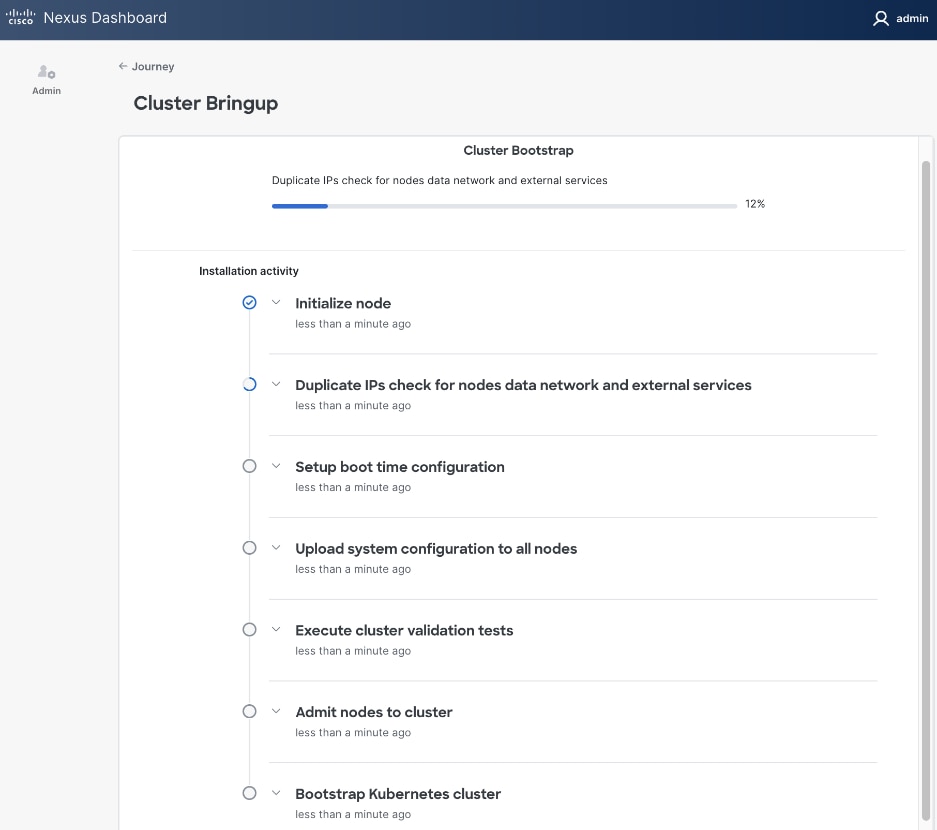
Step 32. Once the workflow finishes, the Cluster Install begins.
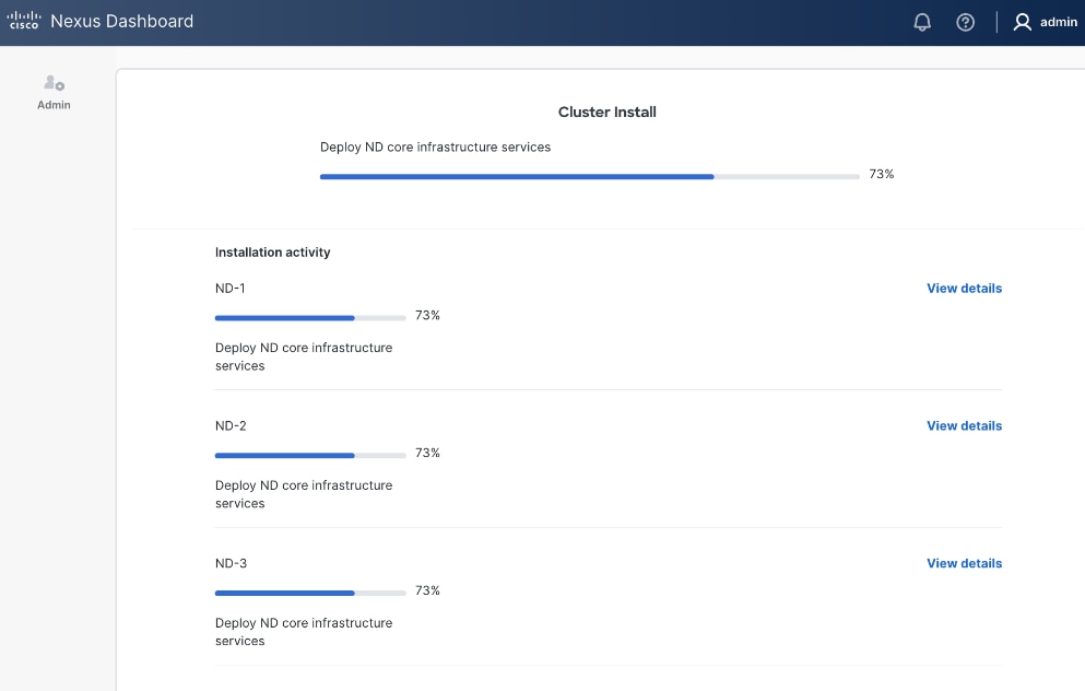
Step 33. Once cluster install completes, the services will be activated. This can take ~ 30 min. for this stage to complete.
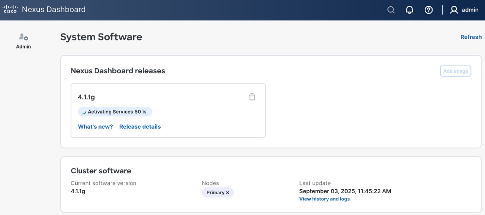
Step 34. Once ND cluster deployment completes, you will see the following status on first ND node at: https://10.115.90.21/system-software.
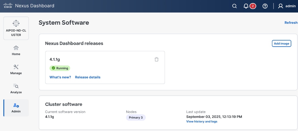
Step 35. You should now see more options on the left navigation menu and not just Admin as was the case earlier.
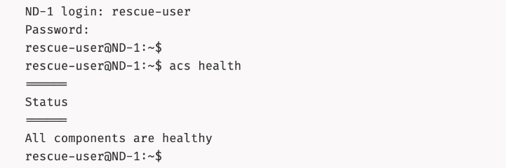
Step 36. SSH into ND nodes and verify the cluster is healthy:
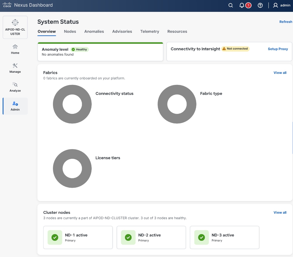
Step 37. From a browser, log back into any of the ND nodes and go to Admin > System Status.
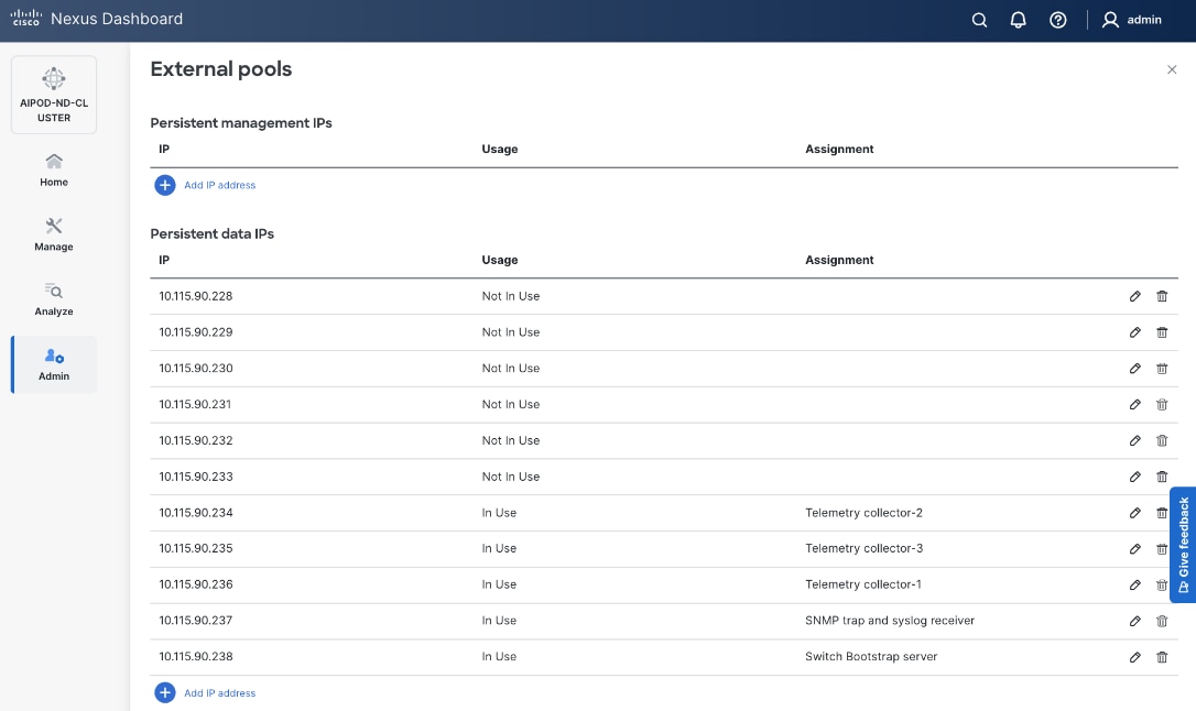
Step 38. You can view how the previously allocated pool of persistent IPs are allocated as various capabilities are deployed on the fabrics being managed by this ND cluster as shown below.
Step 39. Review the overall status and addressing any remaining steps by stepping through the different options in the left navigation menu. For example, some optional but recommended steps could be:
● From AdminAdmin > Intersight, > Intersight, claim ND nodes in cisco.intersight.comcisco.intersight.com using the account (for example AI-POD) that is managing the compute nodes in the solution
● From Admin >Admin > Backup and Restore, Backup and Restore, setup backup and restore to save the ND configuration.
● From Analyze >Analyze > AnomaliesAnomalies and Advisories, Advisories, review and take action or acknowledge them if they are not relevant to your environment.
● From Admin > System Settings, review options in the Fabric Management tab.
● From AdminAdmin > System Settings, > System Settings, review options in the Flow Collection Flow Collection tab to enable Telemetry
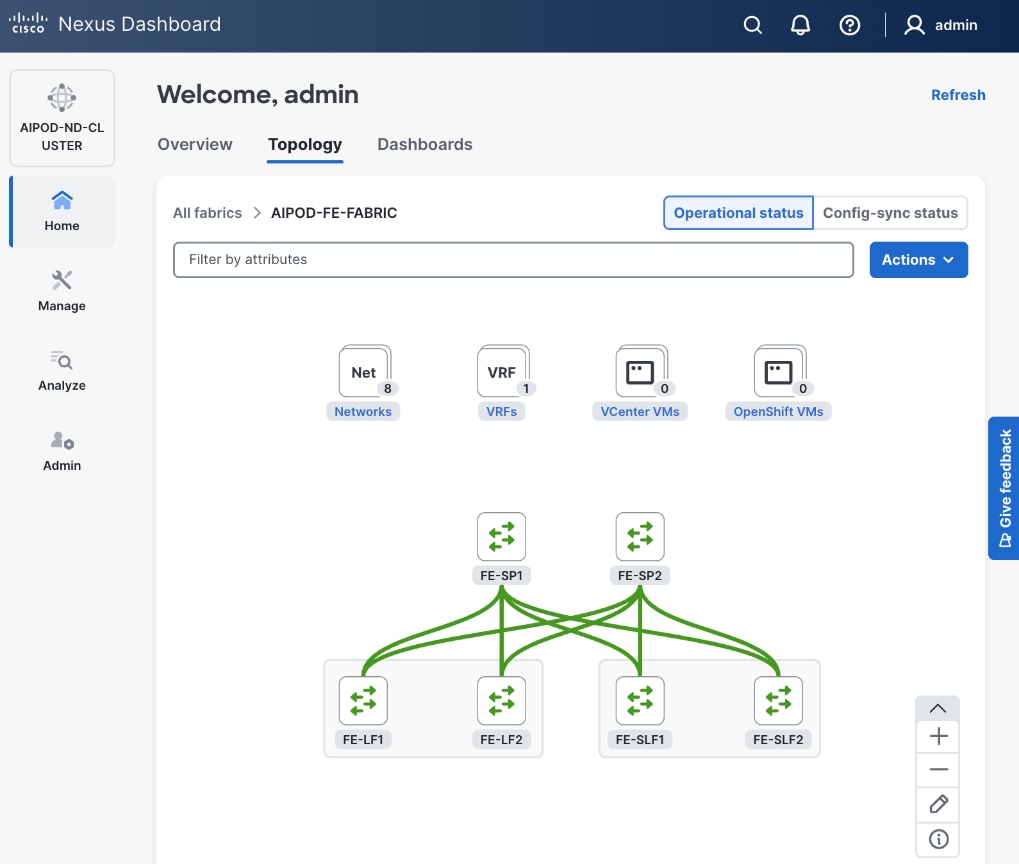
Deploy Frontend Fabric using Nexus Dashboard
The procedures outlined in this section will use Cisco Nexus Dashboard, specifically the fabric templates provided by ND, to deploy the frontend fabric in the AI POD solution. The frontend fabric is a 2-tier, 3-stage spine-leaf Clos topology, built using Cisco Nexus 9000 series data center switches. Once the fabric is deployed, ND will be used to provision connectivity between various infrastructure components connected to the frontend fabric. The Cisco UCS GPU servers in the AI POD training cluster will use the frontend (N-S) NIC to connect to the frontend fabric.
The procedures in this section will:
● Deploy a VXLAN EVPN fabric on the frontend leaf and spine switches, connected in a 2-tier spine-leaf topology
● Enable Virtual Port Channel (vPC) peering on compute/management leaf pairs and storage leaf pairs in the frontend fabric
● Provision L2 and in-band management connectivity to UCS server that will be used to host the control plane and workload management components for the AI workloads running on UCS GPU servers.
● Provisioning external connectivity from the frontend fabric to other enterprise internal and external networks. This includes connectivity to Cisco Intersight, Red Hat Hybrid Cloud Console and other SaaS services used in the AI POD solution.
● Provision Layer 2 and Layer 3 connectivity to Everpure FlashBlade//S from front end fabric as needed.
● Enable reachability between UCS nodes and Everpure FlashBlade//S to enable access to NFS and object data stores.
● Enable QoS in frontend fabric to ensure losses RDMA to the storage system.
Deploy VXLAN EVPN Fabric using Nexus Dashboard Templates
Assumptions and Prerequisites
● Nexus Dashboard cluster deployed
● All switches in the frontend fabric cabled in a spine-leaf topology
● Reachability from ND cluster to switches so that they can be discovered and added to the fabric
Setup Information
Table 8. Setup Parameters for FE Fabric: Deploy VXLAN EVPN Fabric
| Parameter Type |
Parameter Name | Value |
Parameter Type |
| Create new LAN fabric workflow |
||
| Type |
VXLAN |
|
| Fabric Type |
Data Center VXLAN EVPN |
|
| Configuration Mode |
Default |
|
| Name |
AIPOD-FE-Fabric |
|
| Location |
Raleigh, US |
|
| BGP ASN |
65101 |
|
| License Tier for fabric |
Premier |
|
| Enabled Features |
Telemetry |
|
| Add switches without a reload |
Enabled |
|
| Set Default Credentials |
|
|
| Username |
admin |
|
| Password |
<specify> |
|
| Add Switches |
|
|
| Seed IP |
<specify> |
|
| Username |
Admin |
|
| Password |
<specify> |
|
| Max Hops |
<specify> |
|
In this setup, the Nexus frontend fabric consisted of 2 spine and 4 leaf switches. The fabric switch details are listed in Table 9.
Table 9. Setup Parameters for FE Fabric: Fabric Switch Details
| Switch |
Role |
OOB IP |
Firmware |
Model |
| FE-LF1 |
Compute/Management Leaf |
10.115.90.52 |
10.4(5) |
Cisco Nexus 9332D-GX2B |
| FE-LF2 |
Compute/Management Leaf |
10.115.90.53 |
10.4(5) |
Cisco Nexus 9332D-GX2B |
| FE-SLF1 |
Storage Leaf |
10.115.90.54 |
10.4(5) |
Cisco Nexus 9332D-GX2B |
| FE-SLF2 |
Storage Leaf |
10.115.90.55 |
10.4(5) |
Cisco Nexus 9332D-GX2B |
| FE-SP1 |
Spine |
10.115.90.50 |
10.4(5) |
Cisco Nexus 9364D-GX2A |
| FE-SP2 |
Spine |
10.115.90.51 |
10.4(5) |
Cisco Nexus 9364D-GX2A |
Deployment Steps
To deploy a VXLAN EVPN Frontend Fabric, follow the procedures below.
Procedure 1. Deploy VXLAN EVPN fabric on the two-tier spine and leaf switches
Step 1. From a browser, go to the management IP of any node in the Nexus Dashboard cluster. Log in using admin account.
Step 2. From the left navigation menu, go to Manage > Fabrics.
Step 3. Click Actions and select Create Fabric from the drop-down list.
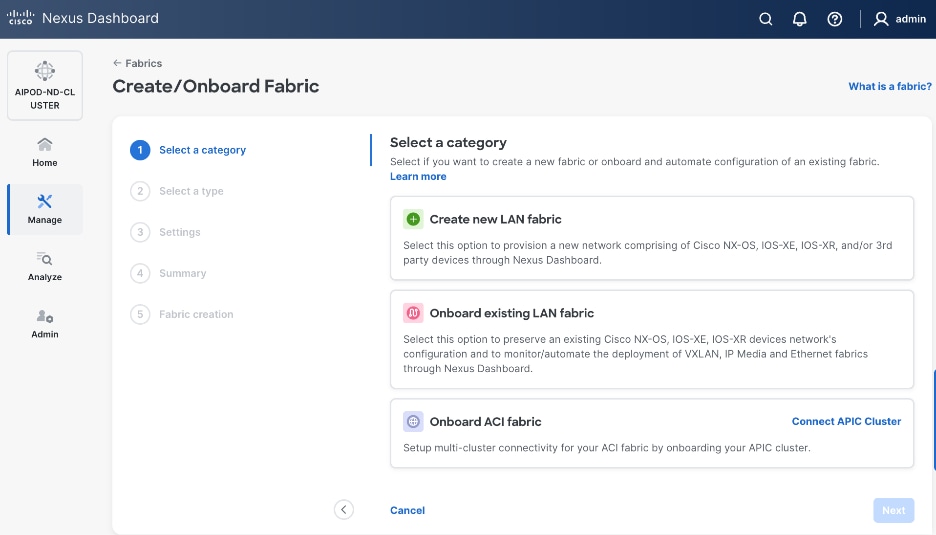
Step 4. Select Create new LAN fabric box. Click Next.
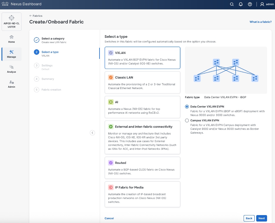
Step 5. Select VXLAN and radio button for Data Center VXLAN EVPN for the fabric type. Click Next.
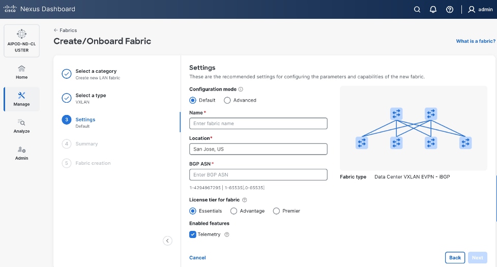
Step 6. For Configuration Mode, keep the Default option. Specify Name, Location, and BGP ASN for fabric. Also select the Licensing tier for fabric from the options available. Premier is required for advanced network analytics and day 2 operations. Click the ? icon to see the features available in each tier.
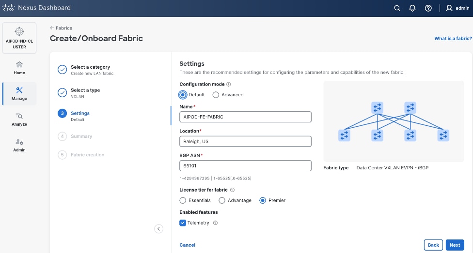
Step 7. Click Next.
Step 8. In the Summary view, verify the settings and click Submit.
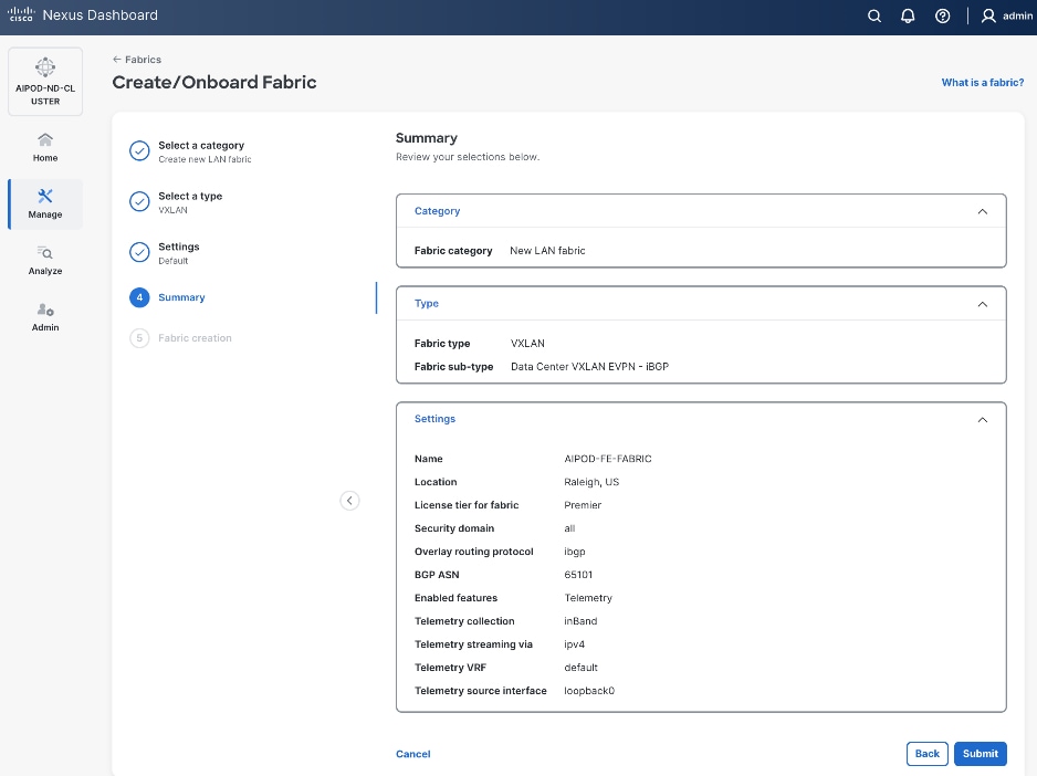
Step 9. Click Submit.
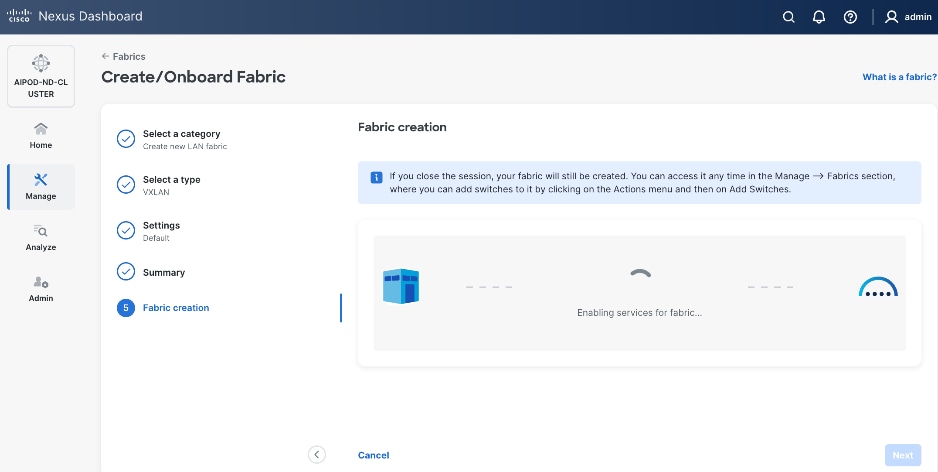
Step 10. When Fabric Creation completes, you will see the following:
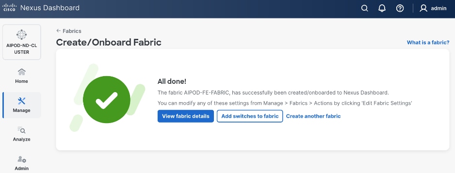
Step 11. To add switches to this new fabric without a reload, click View fabric details. Select Fabric Management > Advanced tabs and scroll down to find the field for Add switches without Reload and change setting to enable. Click Save, followed by Got it in the pop-up window.
Step 12. From the Manage > Fabrics view, click the fabric name to add switches to the fabric.
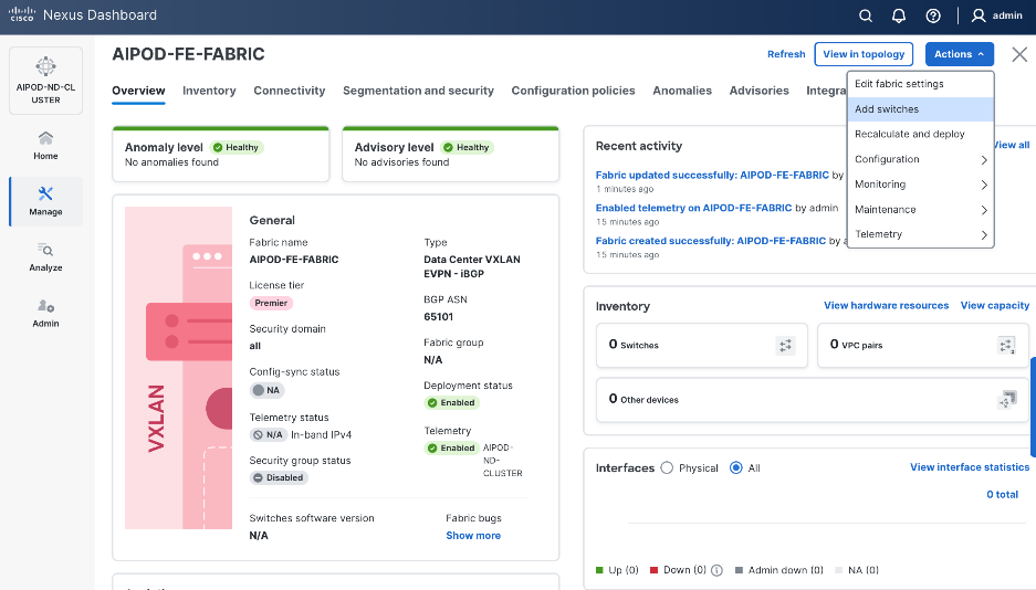
Step 13. Click Actions and select Add Switches from the drop-down list.
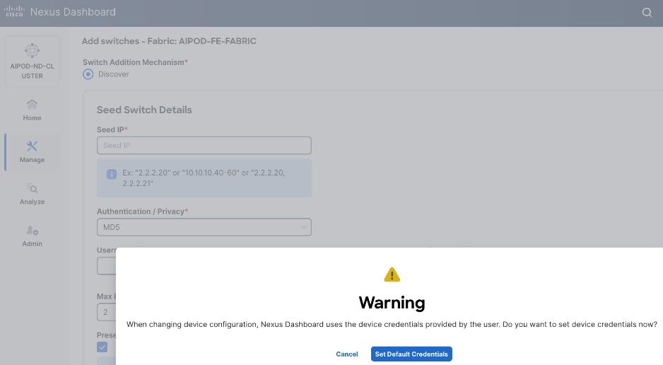
Step 14. In the pop-up window, click Set Default Credentials.
Step 15. Specify username and password. Click Save.
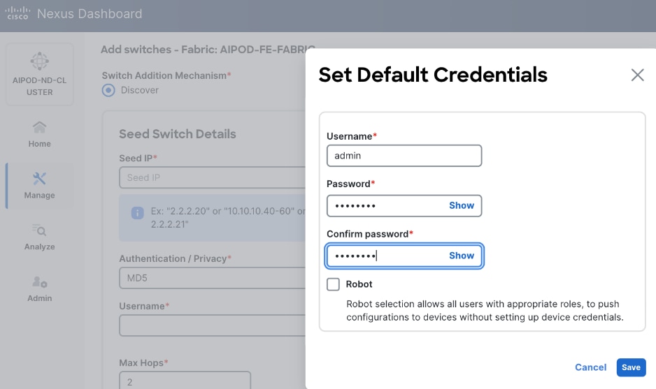
Step 16. Click Ok.
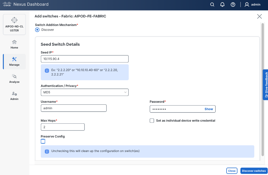
Step 17. Specify Seed IP, username and password. Adjust Max hops as needed. Click Discover Switches.
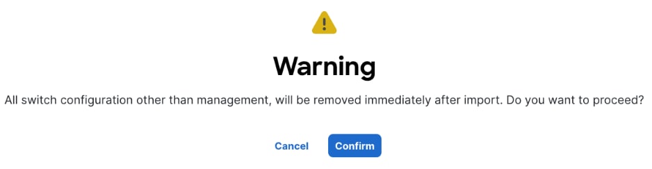
Step 18. Click Confirm in the pop-up Warning.
Step 19. Filter the discovered switch list as needed to view only the switches you want to add.
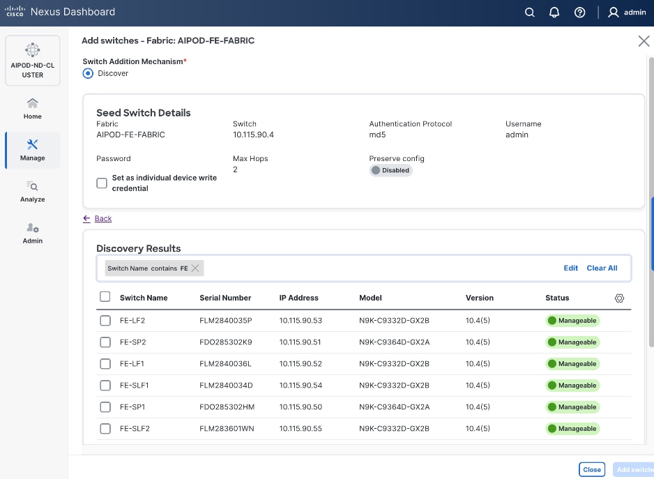
Step 20. Select all switches to be added. Click Add switches.
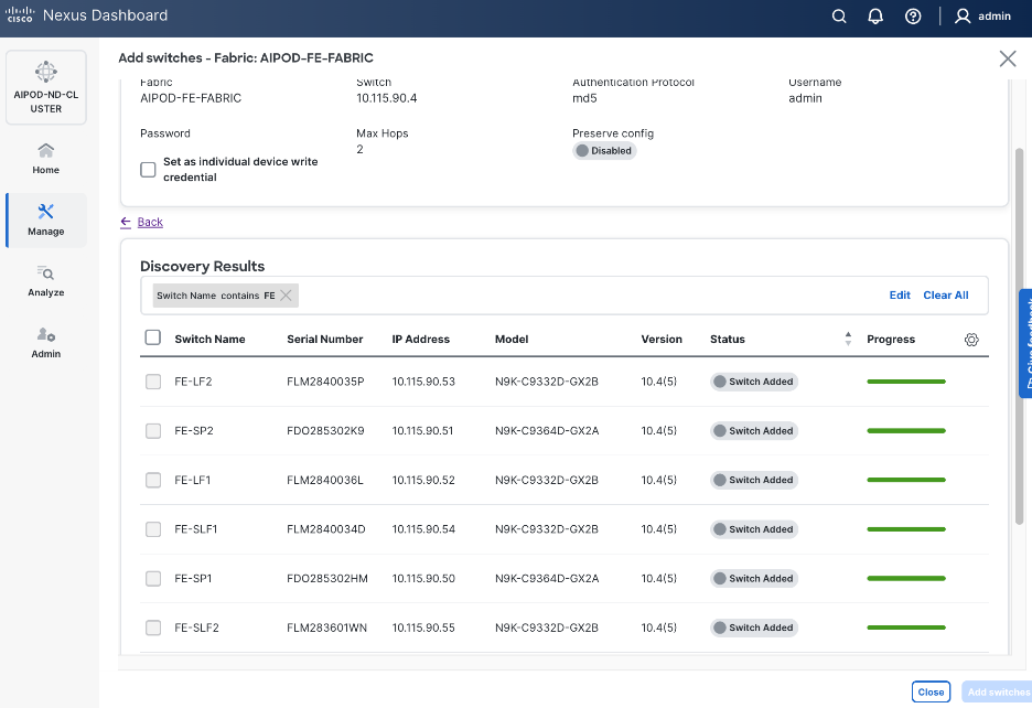
Step 21. Click Close when all switches have been added.
Step 22. From the Manage > Fabrics, select the fabric and click Inventory tab.
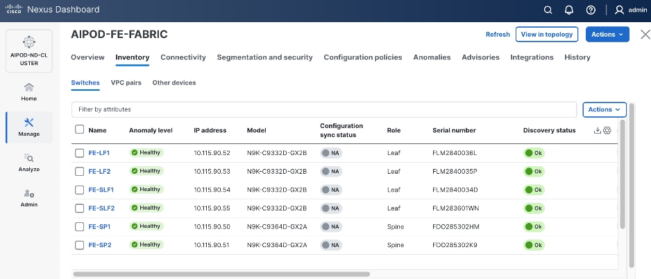
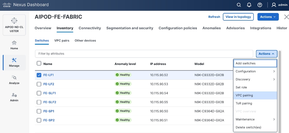
Step 23. For each switch in the list, verify Role is correct. To change the role, select the switch and then click the lower Actions button and select Set role from the drop-down list.
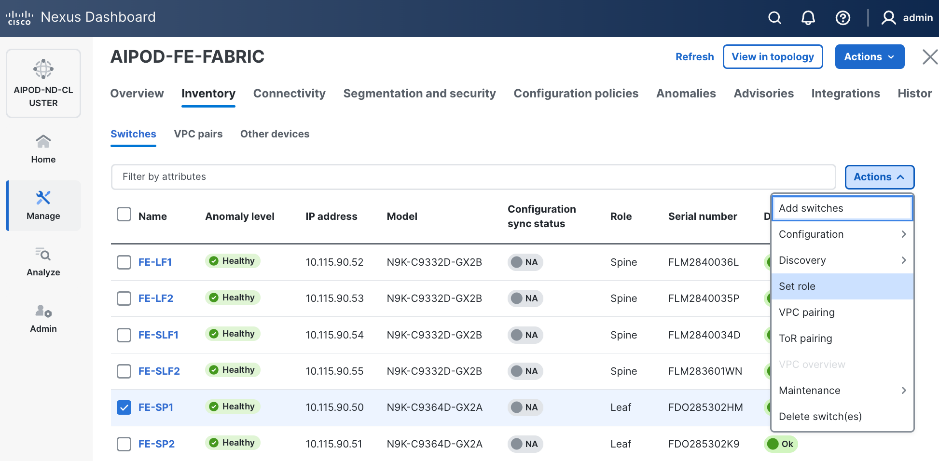
Step 24. In the Select Role pop-up window, select the correct role from the list and click Select.
Step 25. Click Ok in the pop-up warning to perform "Recalculate and deploy" to complete the change.
Step 26. Repeat steps 1 – 25 to select and confirm the role for all switches in the fabric.
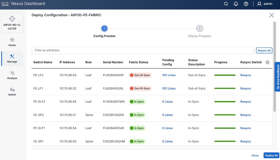
Step 27. Click the upper Actions button and select Recalculate and deploy from the drop-down list. If it says one is already in progress, wait a few minutes and repeat the steps. You should see the Fabric as Out-of-sync with some Pending Config (lines of config) change.
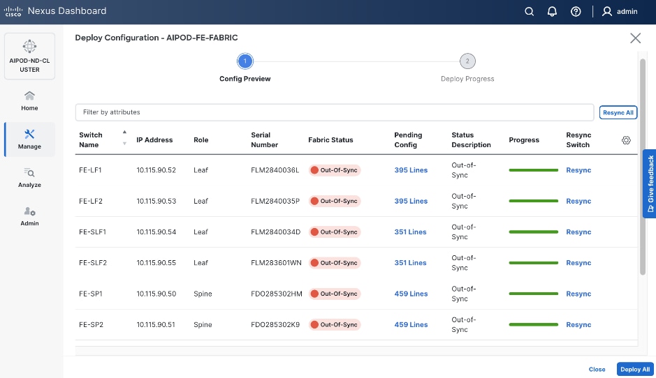
Step 28. Click Deploy All.
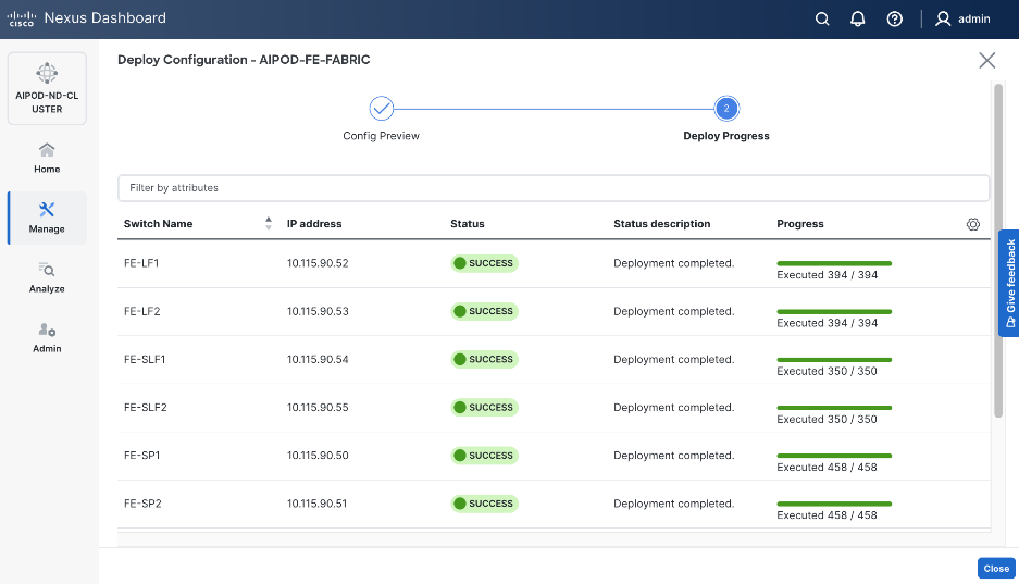
Step 29. Click Close.
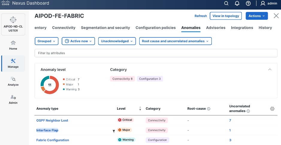
Step 30. ND will identify issues in hardware, connectivity, software etc., reflected by the Anomaly level. To view the flagged anomalies, go to Anomalies in the top menu bar. Address each anomaly to prevent issues later, either by resolving them or acknowledging them.
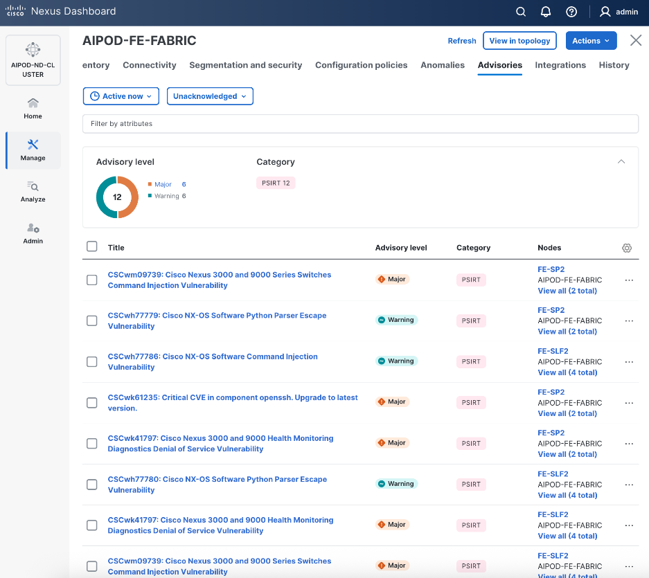
Step 31. Review the Advisories and resolve or acknowledge them.
Step 32. Evaluate and upgrade to Cisco recommended Nexus OS release.
Step 33. Now you can start attaching compute, storage and other end devices to the cluster.
Enable vPC Pairing on Compute/Management Leaf Switches in the FE Fabric
Assumptions and Prerequisites
● Compute/Management Leaf Switches discovered and added to the frontend fabric.
Setup Information
Table 10. Setup Parameters for FE Fabric: Enable vPC Pairing on Compute/Management Leaf Switches
| Parameter Type |
Parameter Name | Value |
Parameter Type |
| vPC Pairing to Compute/Management Leaf Switches |
||
| Enable Virtual Peerlink |
Enabled |
|
| Leaf Switches |
|
|
| Leaf 1 |
FE-LF1 |
|
| Leaf 2 |
FE-LF2 |
|
Deployment Steps
To enable vPC pairing on the compute/management in the frontend fabric, follow the procedures below.
Procedure 1. Enable vPC pairing for compute/management leaf switches in the FE fabric
Step 1. From a browser, go to Nexus Dashboard. Use the management IP of any node in the ND cluster. Log in using admin account.
Step 2. From the left navigation menu, go to Manage > Fabrics.
Step 3. Select the frontend fabric and click Inventory tab.
Step 4. To enable VPC pairing on the leaf switches that connect to UCS compute (GPU and management) nodes, select the first leaf switch in the leaf pair.
Step 5. Click the lower Actions button and select VPC pairing from the drop-down list.
Step 6. Select the VPC peer switch for the first compute/management leaf. Enable Virtual Peerlink.
Step 7. Click Save.
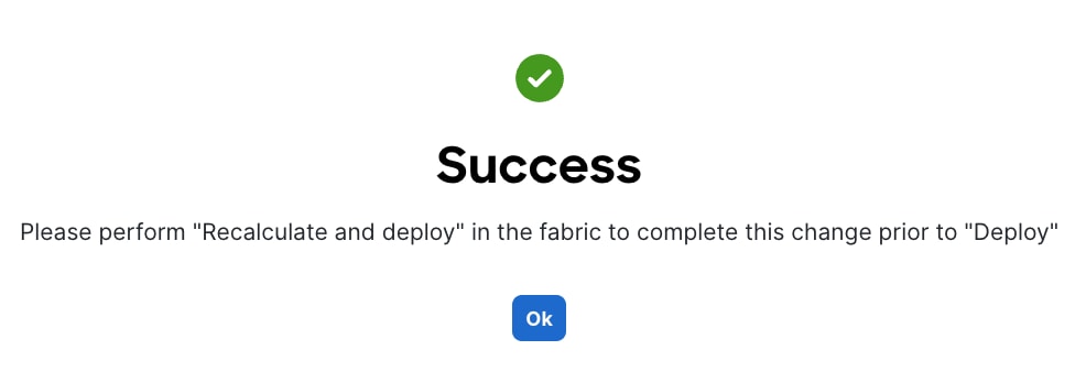
Step 8. Click Ok in the Success pop-up window.
Step 9. Select the two leaf switches in the vPC pair that are now Out-of-sync from the configuration change. Click the upper Actions button and select Recalculate and deploy from the drop-down list.
Step 10. Click Deploy All.
Step 11. When the configuration deployment completes successfully, click Close.
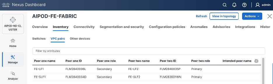
Step 12. In the Inventory tab, go to VPC pairs tab to see the newly created vPC pair.
Enable vPC Pairing on Storage Leaf Switches in the Frontend Fabric
Assumptions and Prerequisites
● Storage Leaf Switches discovered and added to the frontend fabric
Setup Information
Table 11. Setup Parameters for FE Fabric: Enable vPC Pairing on Storage Leaf Switches
| Parameter Type |
Parameter Name | Value |
Parameter Type |
| vPC Pairing to Storage Leaf Switches |
||
| Enable Virtual Peerlink |
Enabled |
|
| Leaf Switches |
|
|
| Leaf 1 |
FE-SLF1 |
|
| Leaf 2 |
FE-SLF2 |
|
Deployment Steps
To enable vPC pairing for the storage leaf switches in the frontend fabric, follow the procedures below.
Procedure 1. Enable vPC pairing for storage leaf switches in the FE fabric
Step 1. Repeat the previous procedure to configure storage leaf switches in the frontend fabric as vPC peers.
Step 2. In the Inventory tab, go to VPC pairs tab to see the newly created vPC pairs.
Step 3. From the left navigation menu, go to Manage > Fabric and select the frontend fabric.
Step 4. Select the Topology tab. You should see the 2 Leaf switch pairs grouped in a box, indicating they are part of the same vPC pair.
Enable Layer 2 Connectivity to Management UCS X-Direct from FE fabric
To enable Layer 2 connectivity to management UCS X-Direct chassis, you will configure two vPCs, one for -A side and another for -B side. Each vPC will use multiple ports on each compute leaf switch pair to connect to -A and -B uplinks on the Cisco UCS X-Direct chassis.
Assumptions and Prerequisites
● Compute/management leaf switches deployed as a vPC pair
● Management UCS-X Direct cabled using multiple uplinks to frontend compute/management leaf switches
Setup Information
Table 12. Setup Parameters for FE Fabric: Layer 2 Connectivity to Management UCS X–Direct
| Parameter Type |
Parameter Name | Value |
Parameter Type |
| Leaf Switches |
FE-LF1, FE-LF2 |
|
| Management UCS |
UCS X-Direct with (-A, -B) uplinks; Both uplinks are dual-homed to FE-LF1 & FE-LF2 |
With multiple servers |
| Virtual Port Channel (vPC) |
To UCS X-Direct |
Management UCS-X Direct Chassis |
| vPC/PC1 - ID |
15 |
To UCS X-Direct: Side-A |
| vPC Pair |
FE-LF1, FE-LF2 |
|
| Ports |
1/5, 1/7 |
FI-A: Ports 1/1-4 (PC-11) |
| vPC/PC2 – ID |
16 |
To UCS X-Direct: Side-B |
| Ports |
1/6, 1/8 |
FI-B: Ports 1/1-4 (PC-12) |
Deployment Steps
To enable Layer 2 connectivity to management Cisco UCS X-Direct chassis from the frontend fabric, follow the procedures below using the setup information provided in this section.
Procedure 1. Deploy first vPC to Management UCS X-Direct
Step 1. From a browser, go to Nexus Dashboard. Use the management IP of any node in the ND cluster. Log in using admin account.
Step 2. From the left navigation menu, go to Manage > Fabrics.
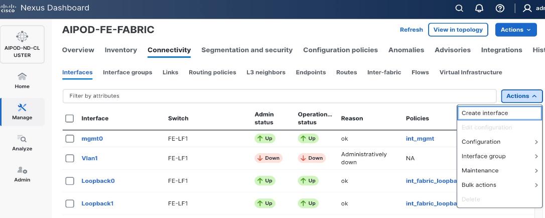
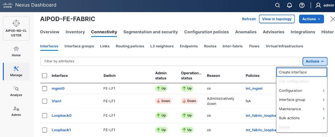
Step 3. Select the frontend fabric and go to Connectivity > Interfaces tab.
Step 4. Click the lower Actions button and select Create interface.
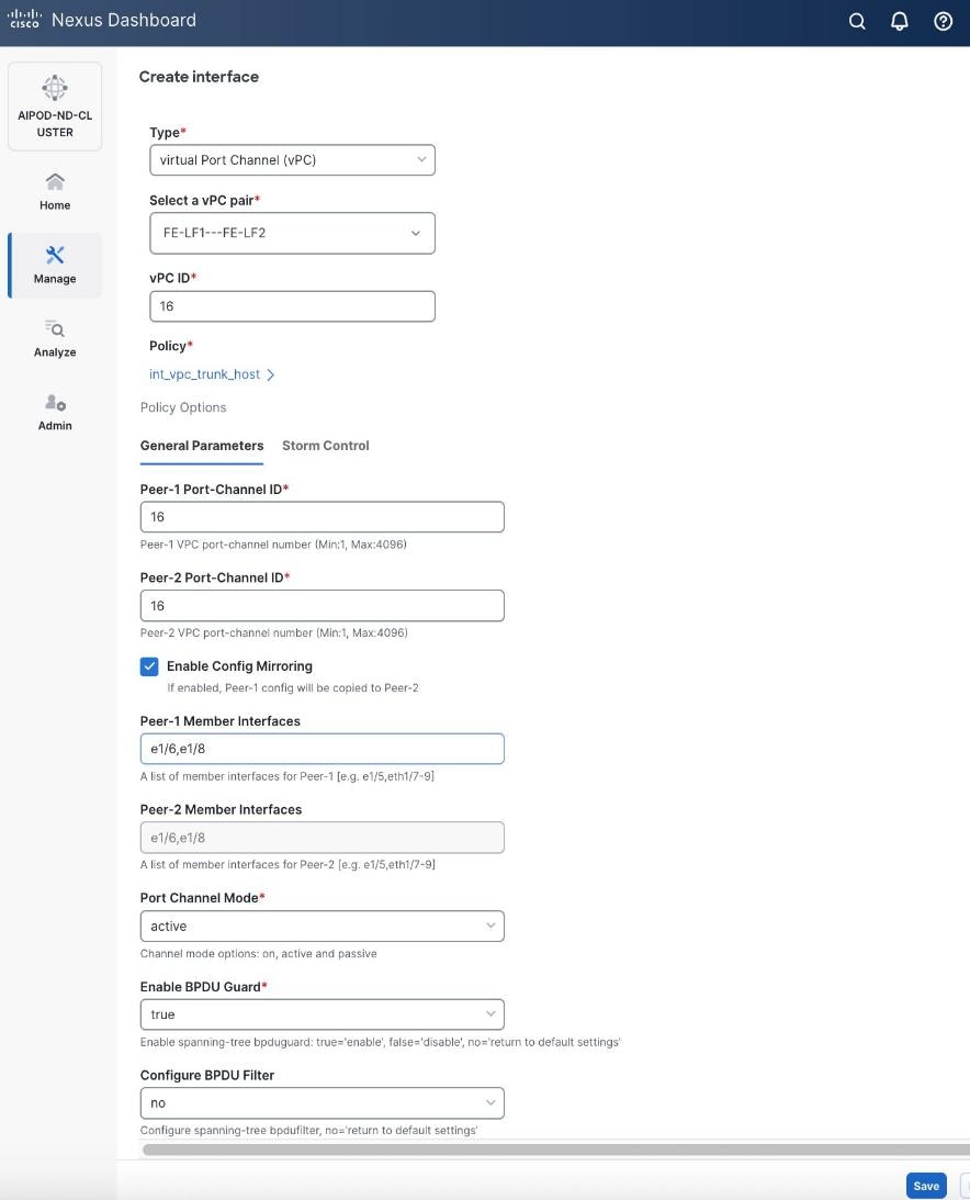
Step 5. In the Create interface window:
● Specify the TypeType of interface as virtual Port Channel (vPC)virtual Port Channel (vPC) from the drop-down list.
● For the Select a vPC pairSelect a vPC pair, select the compute leaf switch vPC pair from the dropdown list.
● Specify a vPC IDvPC ID for the firstfirst vPC to the UCS X-Direct (-A side-A side). Port Channel IDs from each switch to the first UCS node should match the vPC ID (see screenshot below).
● Leave the Policy as int_vpc_trunk_host.
● EnableEnable checkbox for Config MirroringConfig Mirroring to configure both vPC peer switches identically.
● Specify Peer-1 Member InterfacesPeer-1 Member Interfaces that connects to first UCS node.
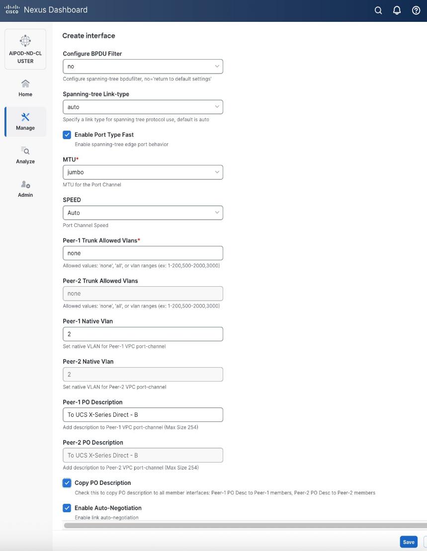
● Leave other fields as is.
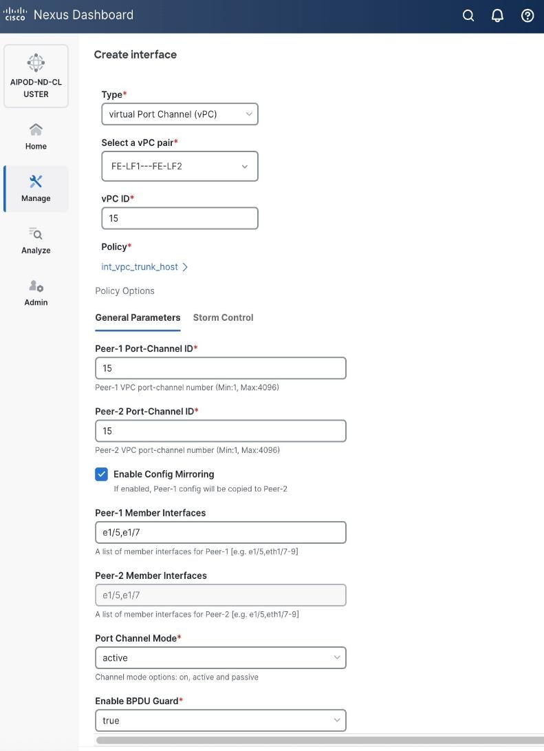
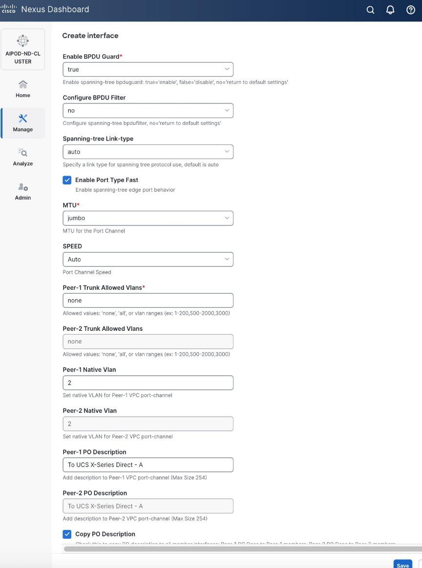
● Scroll down and fill remaining fields: Native VLANNative VLAN, Peer-1 PO Description, Peer-1 PO Description, and select the checkbox for Copy PO Description Copy PO Description to copy the description to second vPC peer’s Port Channel.
Step 6. Click Save.
Step 7. Click Preview.
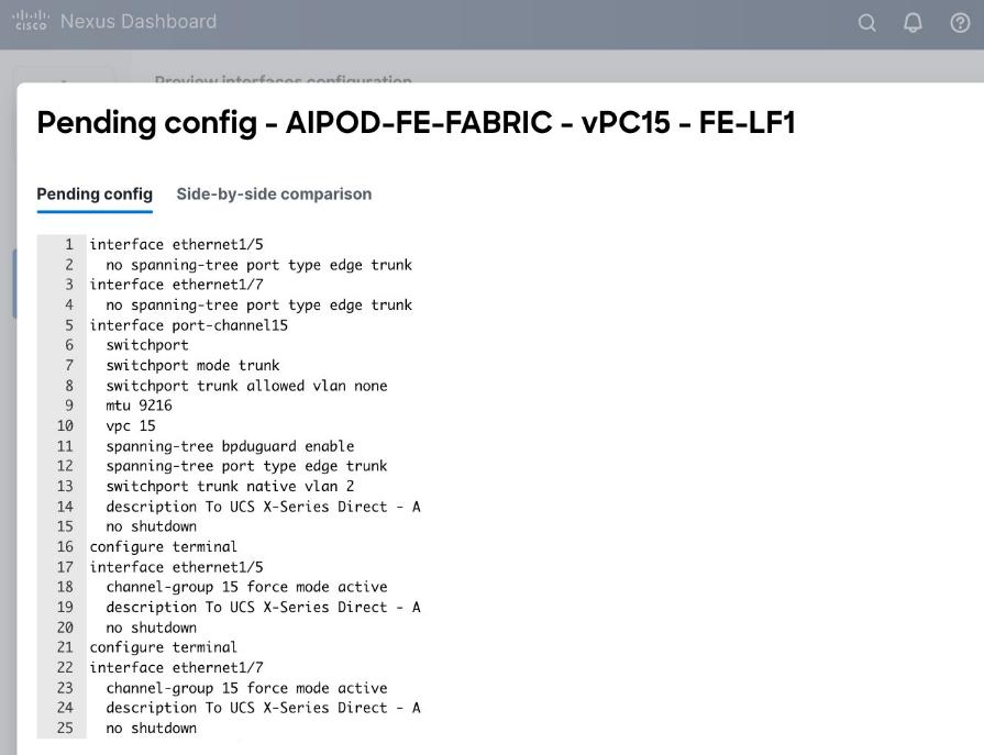
Step 8. Click Close and then click Cancel.
Step 9. Click Deploy. The Pending Config is the configuration shown in the previous step.
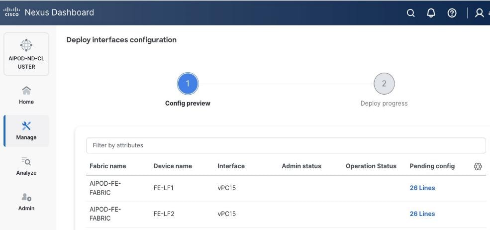
Step 10. Click Deploy Config.
Step 11. Verify that all the interfaces and port-channels are up on each switch in the vPC leaf pair that connects to the UCS X-Direct (-A side). It may take a few minutes for the vPC to go from Not discovered to consistent state.
Procedure 2. Deploy second vPC to Management UCS X-Direct
Step 1. Repeat the previous procedure for the second vPC to UCS X-Direct (-B side).
Step 2. Click Save.
Step 3. Click Deploy then click Deploy Config.
Step 4. Verify that all the interfaces and port-channels are up on each switch in the vPC leaf pair that connects to the UCS X-Direct (-B side). It may take a few minutes for the vPC to go from Not discovered to consistent state.
Enable Layer 2 Connectivity to UCS GPU Nodes from FE Fabric
To enable layer 2 connectivity to UCS GPU nodes, you will be configuring four vPCs, one per Cisco UCS C885A node. Each vPC will use one port on each switch in the compute leaf pair to connect to the UCS node.
Assumptions and Prerequisites
● Compute/management leaf switches deployed as a vPC pair
● Frontend NICs on UCS GPU nodes dual-homed to compute/management leaf switches
Setup Information
Table 13. Setup Parameters for FE Fabric: Layer 2 Connectivity to UCS GPU Nodes
| Parameter Type |
Parameter Name | Value |
Parameter Type |
| Leaf Switches |
FE-LF1, FE-LF2 |
|
| UCS Nodes |
4 x UCS C885A GPU Nodes, each dual-homed to FE-LF1 & FE-LF2 |
|
| Virtual Port Channel (vPC) |
To UCS C885As |
UCS GPU Nodes |
| vPC/PC1 - ID |
111 |
|
| vPC Pair |
FE-LF1, FE-LF2 |
|
| Ports |
1/1 |
On each Leaf switch |
| vPC/PC2 – ID |
112 |
|
| vPC Pair |
FE-LF1, FE-LF2 |
|
| Ports |
1/2 |
On each Leaf switch |
| vPC/PC3 - ID |
113 |
|
| vPC Pair |
FE-LF1, FE-LF2 |
|
| Ports |
1/3 |
On each Leaf switch |
| vPC/PC4 – ID |
114 |
|
| vPC Pair |
FE-LF1, FE-LF2 |
|
| Ports |
1/4 |
On each Leaf switch |
Deployment Steps
To enable Layer 2 connectivity from the frontend fabric to UCS C885A GPU nodes, follow the procedures below using the setup information provided in this section.
Procedure 1. Deploy first vPC to first UCS C885A GPU node
Step 1. From a browser, go to Nexus Dashboard. Use the management IP of any node in the ND cluster. Log in using admin account.
Step 2. From the left navigation menu, go to Manage > Fabrics.
Step 3. Select the frontend fabric and go to Connectivity > Interfaces tab.
Step 4. Click the lower Actions button and select Create interface.
Step 5. In the Create interface window:
● Specify the TypeType of interface as virtual Port Channel (vPC)virtual Port Channel (vPC) from the drop-down list.
● For the Select a vPC pairSelect a vPC pair, select the compute leaf switch VPC pair from the dropdown list.
● Specify a vPC IDvPC ID for the vPC to the first first UCS GPU node. Peer-1 and Peer-2 Port-Channel ID should match that of the vPC ID.
● Leave the Policy as int_vpc_trunk_hostint_vpc_trunk_host.
● Enable checkbox for Config MirroringConfig Mirroring.
● Specify Peer-1 Member InterfacesPeer-1 Member Interfaces that connects to first UCS node.
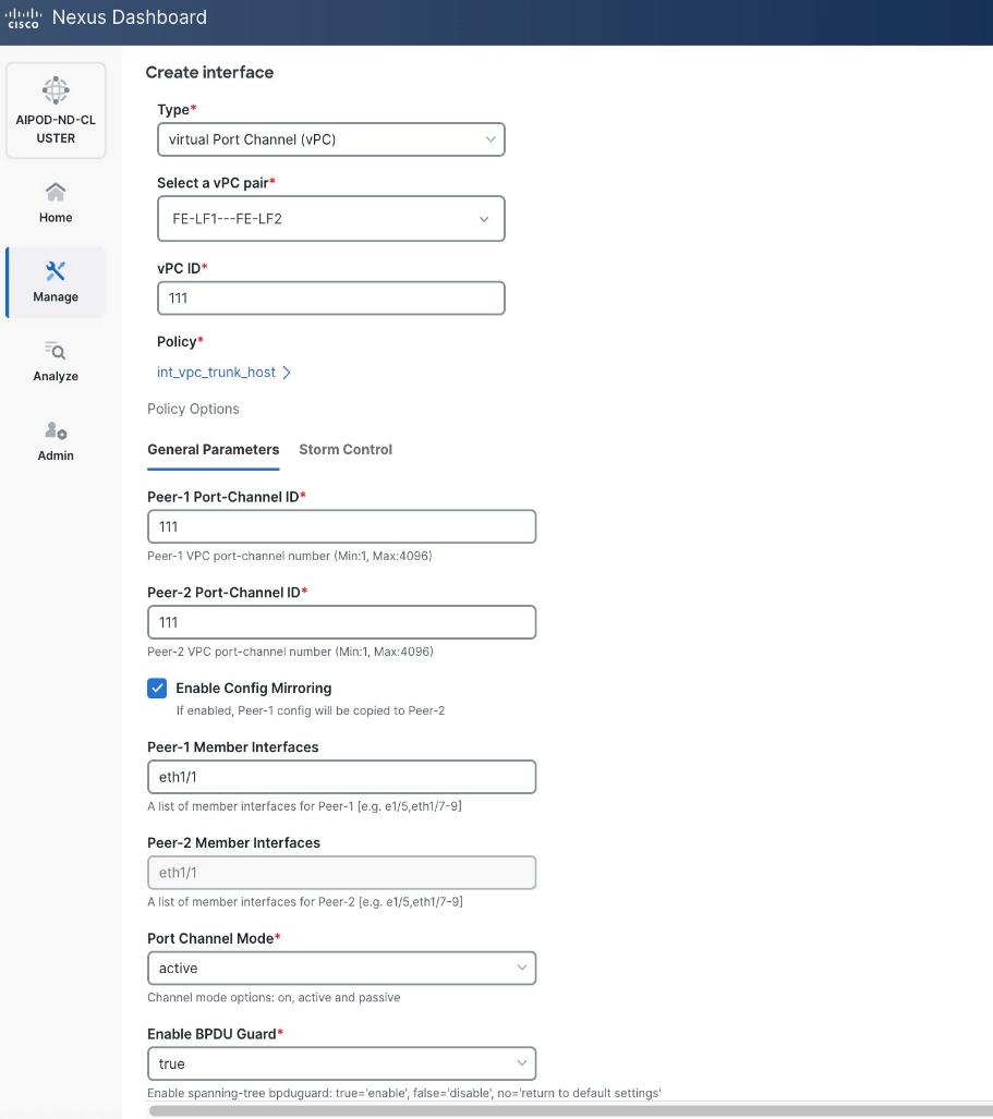
● Specify Peer-1 Native Vlan.
● Specify Peer-1 PO Description.
● EnableEnable the checkbox for Copy PO DescriptionCopy PO Description to copy PO description to all member interfaces
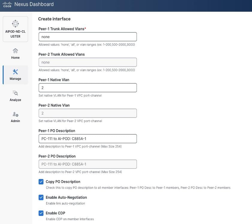
Step 6. Additional configuration changes can be made later as needed. Click Save.
Step 7. Click Preview to view the Pending config changes.
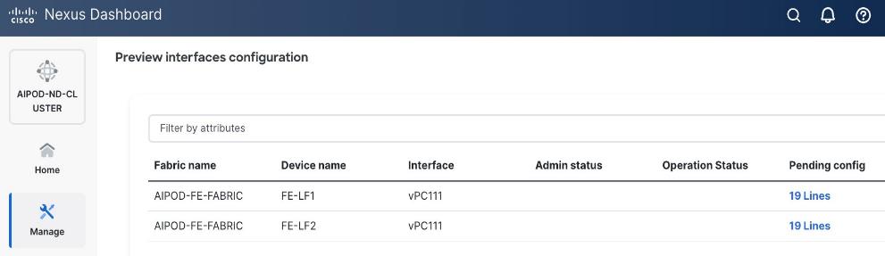
Step 8. Click the Pending Config for each switch to see the configuration.
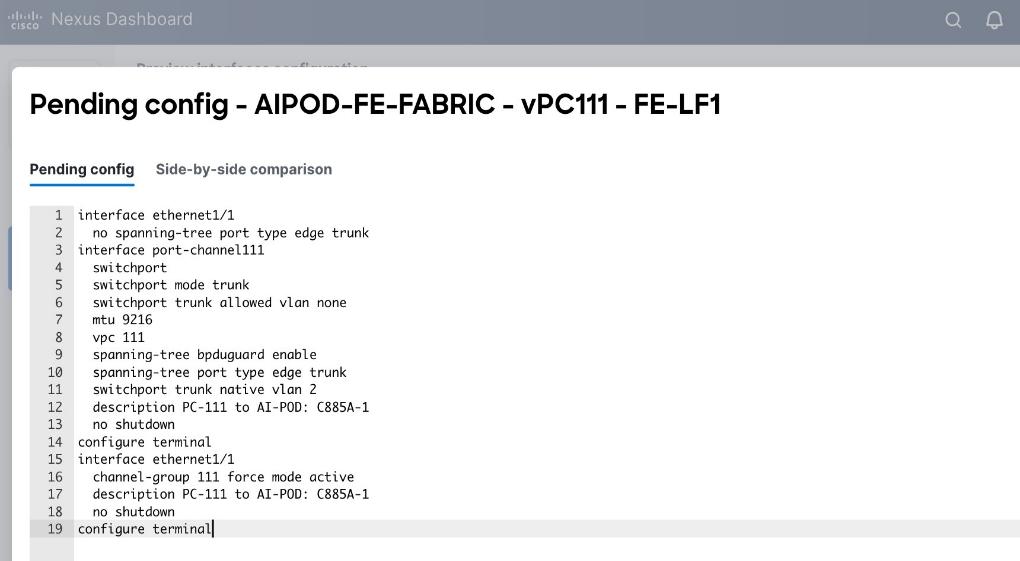
Step 9. Click the X in the top right corner and select Deploy and Deploy config to deploy the Pending config changes.
Step 10. Click Close when deployment completes successfully.
Step 11. Verify that all the interfaces and port-channel is up on each switch in the leaf switch pair that connects to the UCS node. It may take a few minutes for the vPC to go from Not discovered to consistent state.
Procedure 2. Deploy vPCs to remaining UCS C885A GPU nodes
Step 1. Repeat the previous procedure to provision layer 2 connectivity from the compute/management leaf switches to the remaining 3 UCS nodes in the cluster.
Step 2. Verify that all the interfaces and port-channel is up on each switch in the leaf switch pair that connects to the UCS nodes. It may take a few minutes for the vPC to go from Not discovered to consistent state.
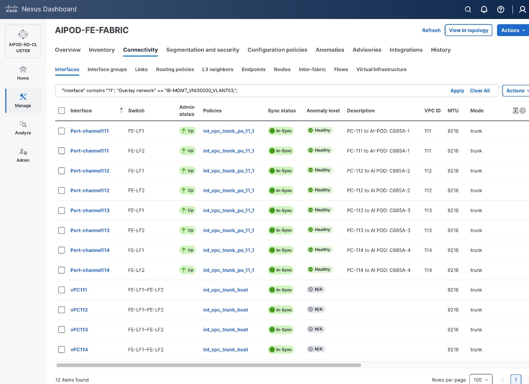
Enable In-Band Management Connectivity to UCS GPU and Management Nodes
The In-band management (IB-MGMT) network in the frontend fabric will provide the following connectivity:
● Connectivity from control, management and services nodes to the UCS GPU nodes where the AI workload is running
● Connectivity to other networks (networks outside this frontend fabric to other networks within the enterprise or external to the enterprise)
In a Red Hat OpenShift environment, this network will also serve as the Cluster IP network for the OpenShift cluster running on UCS management (Kubernetes Control) nodes and UCS GPU (Kubernetes Worker) nodes.
Assumptions and Prerequisites
● Layer 2 connectivity in place from frontend fabric to UCS management/control nodes
● Layer 2 connectivity in place from frontend fabric to UCS GPU nodes is in place
Setup Information
Table 14. Setup Parameters for FE Fabric: In-Band Management Connectivity to UCS Management and GPU Nodes
| Parameter Type |
Parameter Name | Value |
Parameter Type |
| IB-MGMT Network |
|
|
| Name |
IB-MGMT_VN30000_VLAN703 |
|
| Layer 2 Only |
No |
|
| IB-MGMT VRF |
|
|
| VRF Name |
FE-MGMT_VN50000 |
|
| VRF ID |
50000 |
(System Proposed) |
| VLAN ID |
2000 |
(System Proposed) |
| VRF Interface Description |
FE-MGMT VRF |
|
| VRF Description |
Frontend Fabric – Management VRF |
|
| IB-MGMT Network Contd. |
|
|
| Network ID |
30000 |
|
| VLAN ID |
703 |
|
| IPv4 Gateway/Netmask |
10.115.90.126/26 |
|
| VLAN Name |
IB-MGMT_VLAN |
|
| Interface Description |
IB-MGMT |
|
| UCS C885A GPU Nodes |
|
|
| vPC Leaf Switch Pair |
FE-LF1, FE-LF2 |
vPC Leaf Switch Pair |
| UCS C885-A Node-1 Interface |
Port-Channel 111 |
|
| UCS C885-A Node-2 Interface |
Port-Channel 112 |
|
| UCS C885-A Node-3 Interface |
Port-Channel 113 |
|
| UCS C885-A Node-4 Interface |
Port-Channel 114 |
|
| Management UCS X-Direct Chassis |
|
|
| vPC Leaf Switch Pair |
FE-LF1, FE-LF2 |
|
| UCS X-Direct (-A Uplinks) |
Port-Channel 15 |
|
| UCS X-Direct (-B Uplinks) |
Port-Channel 16 |
|
Deployment Steps
To deploy the in-band management network and enable connectivity to the UCS GPU nodes, follow the procedures below.
Procedure 1. Deploy In-Band Management Connectivity for UCS GPU Nodes
Step 1. From a browser, go to Nexus Dashboard. Use the management IP of any node in the ND cluster. Log in using admin account.
Step 2. From the left navigation menu, go to Manage > Fabrics.
Step 3. Select the frontend fabric and go to Segmentation and Security > Networks tab.
Step 4. Click the lower Actions button and select Create from the list.
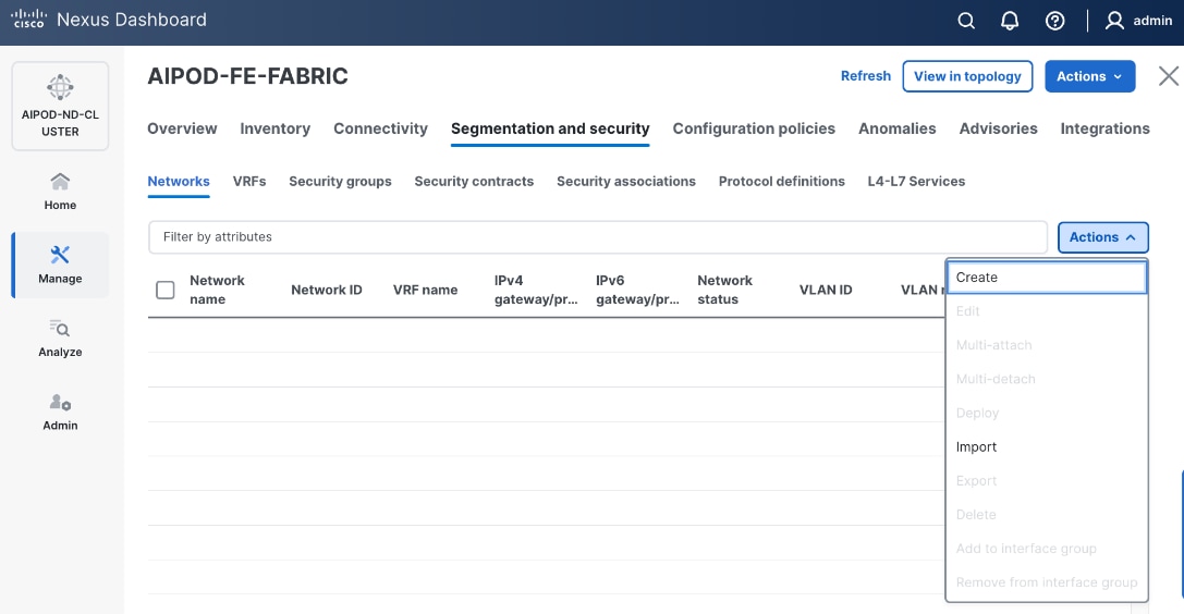
Step 5. In the Create Network window, specify the following:
● Network nameNetwork name for the IB-MGMT network.
● Leave unchecked the Layer 2 only Layer 2 only checkbox as IB-MGMT is a layer 3 overlay network.
● VRF nameVRF name. If a VRF hasn't been created already, you have an option from this window to also create a VRF.
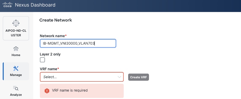
● To create a new VRF, click Create Create VRF. In the Create VRF Create VRF window, specify VRF ID (VRF ID (or use default), VLAN ID (VLAN ID (or click Propose VLAN Propose VLAN to let system define a VLAN), and optionally other parameters as shown below:
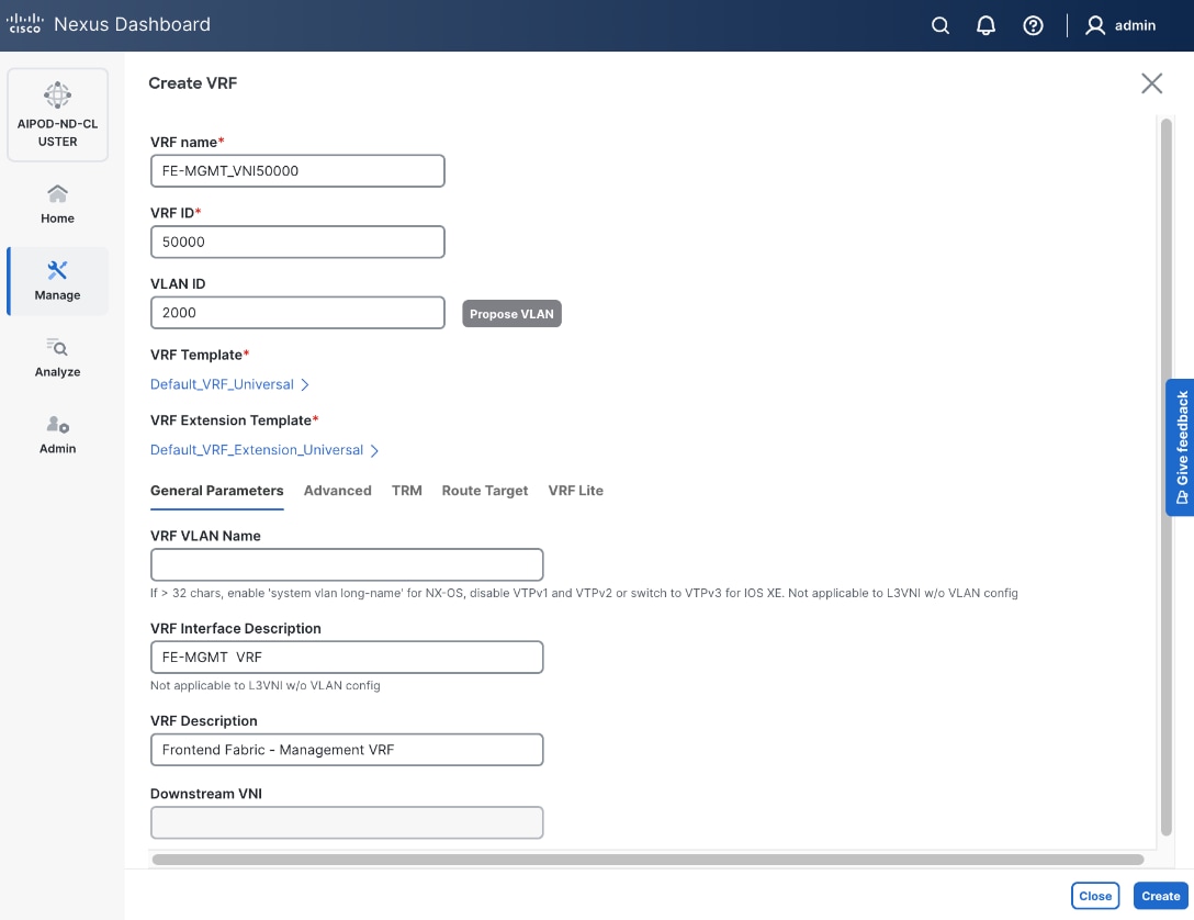
Step 6. Click Create to create the VRF and return to the Create Network window.
Step 7. In the Create Network window, specify the following:
● Network IDNetwork ID or use default.
● VLAN ID VLAN ID or click Propose VLAN Propose VLAN button to let system define a VLAN.
● In the General Parameters tab, specify IP Gateway/Netmask, VLAN Name and Interface Description.
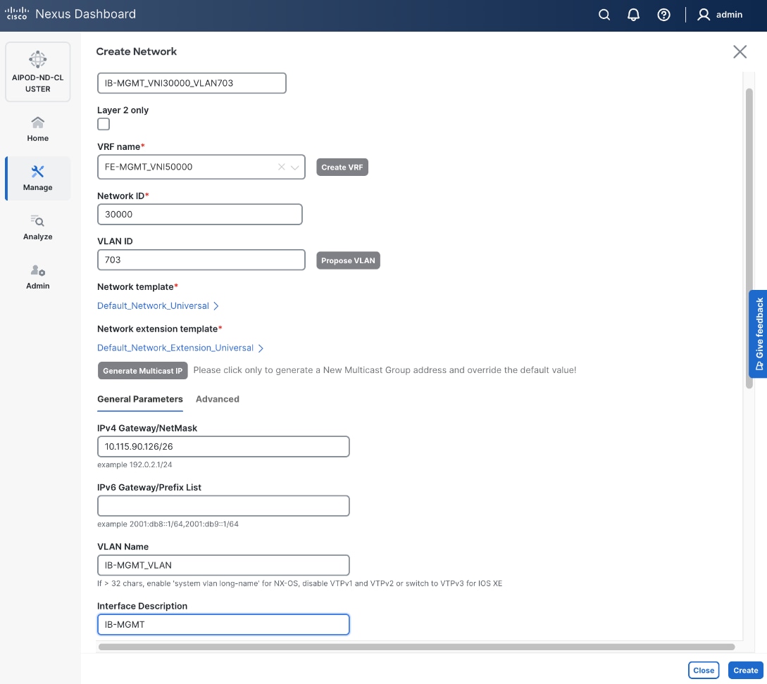
Step 8. Click Create to create the Network.
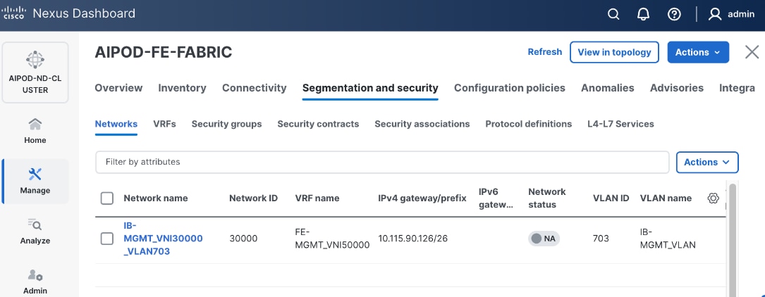
Step 9. Select newly created network and deploy it on both leaf pairs. Click the lower Actions button and select Multi-attach from the list.
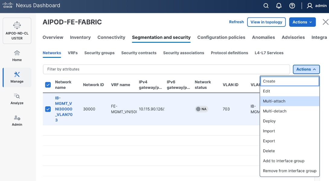
Step 10. Select the Leaf switch pairs. Enabling this network on storage leaf pairs as shown below may not be necessary in all deployments.
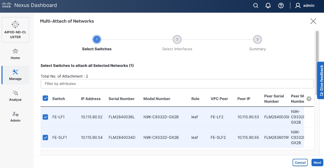
Step 11. Click Next.
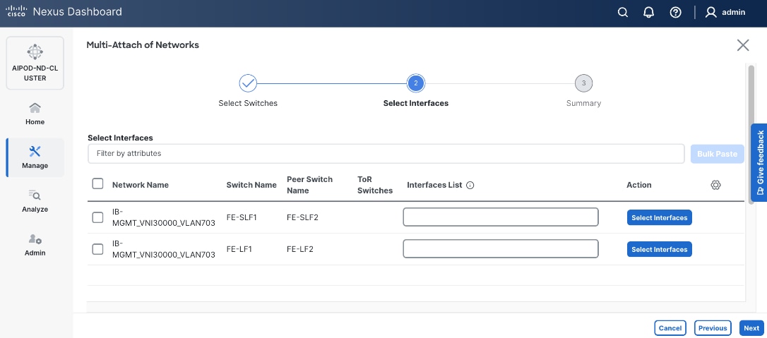
Step 12. Select each switch pair in the list and click Select interfaces button on the right to deploy this network as a trunked VLAN (VLAN 703) on the selected interfaces. For now, select the interfaces on the compute leaf switches that connect to the UCS GPU nodes. Additional interfaces can be added later as needed.
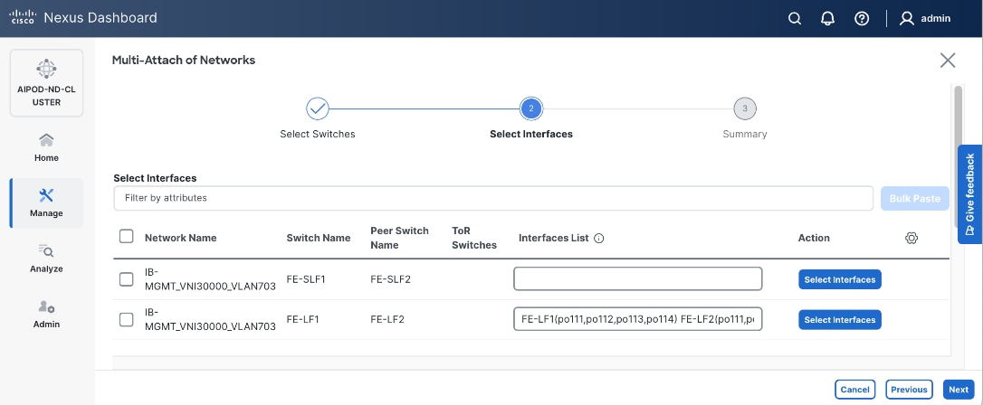
Step 13. Click Next.
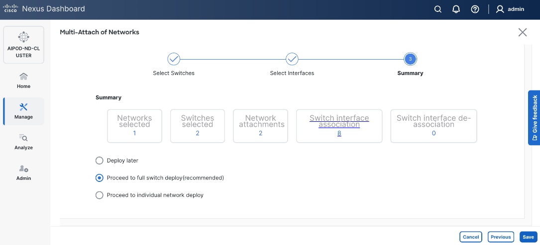
Step 14. Click Save.
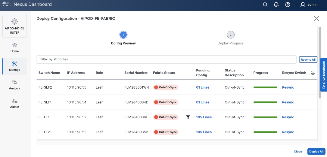
Step 15. Click Pending Config to see the configuration being deployed. The pending configuration on one leaf switch is provided as a reference at the end.
Step 16. Click Deploy All.
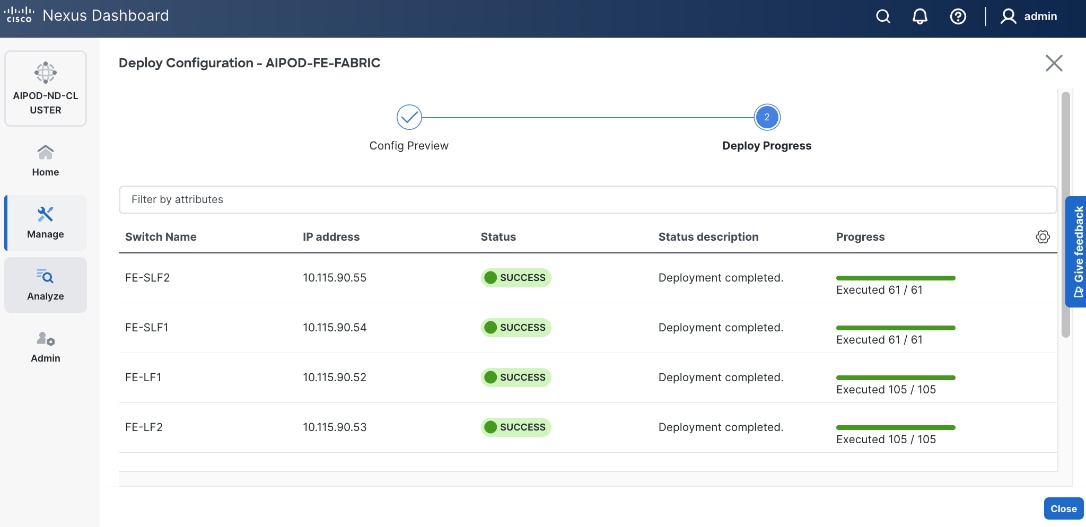
Step 17. Click Close.
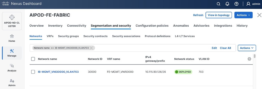
Step 18. Click the Network name to verify that the network was successfully deployed on the relevant switches and interfaces.
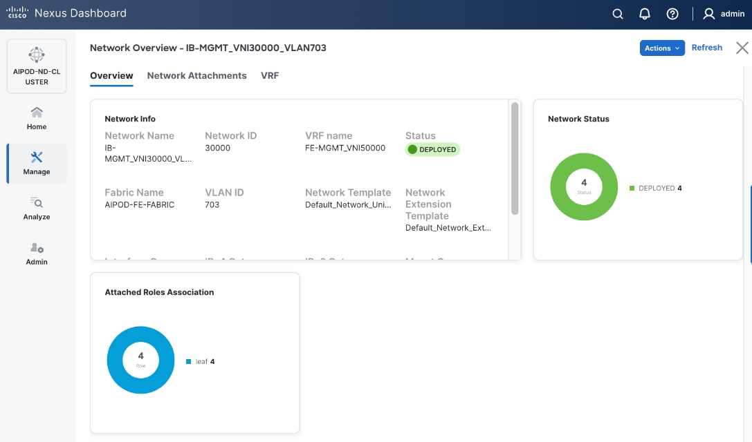
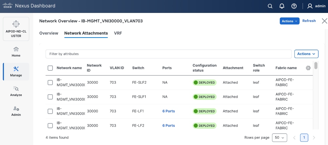
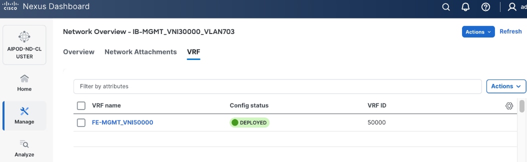
The configuration deployed on one compute leaf switch is provided below as a reference. For complete switch configs, see AI POD GitHub repo.
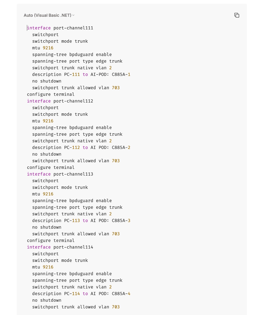
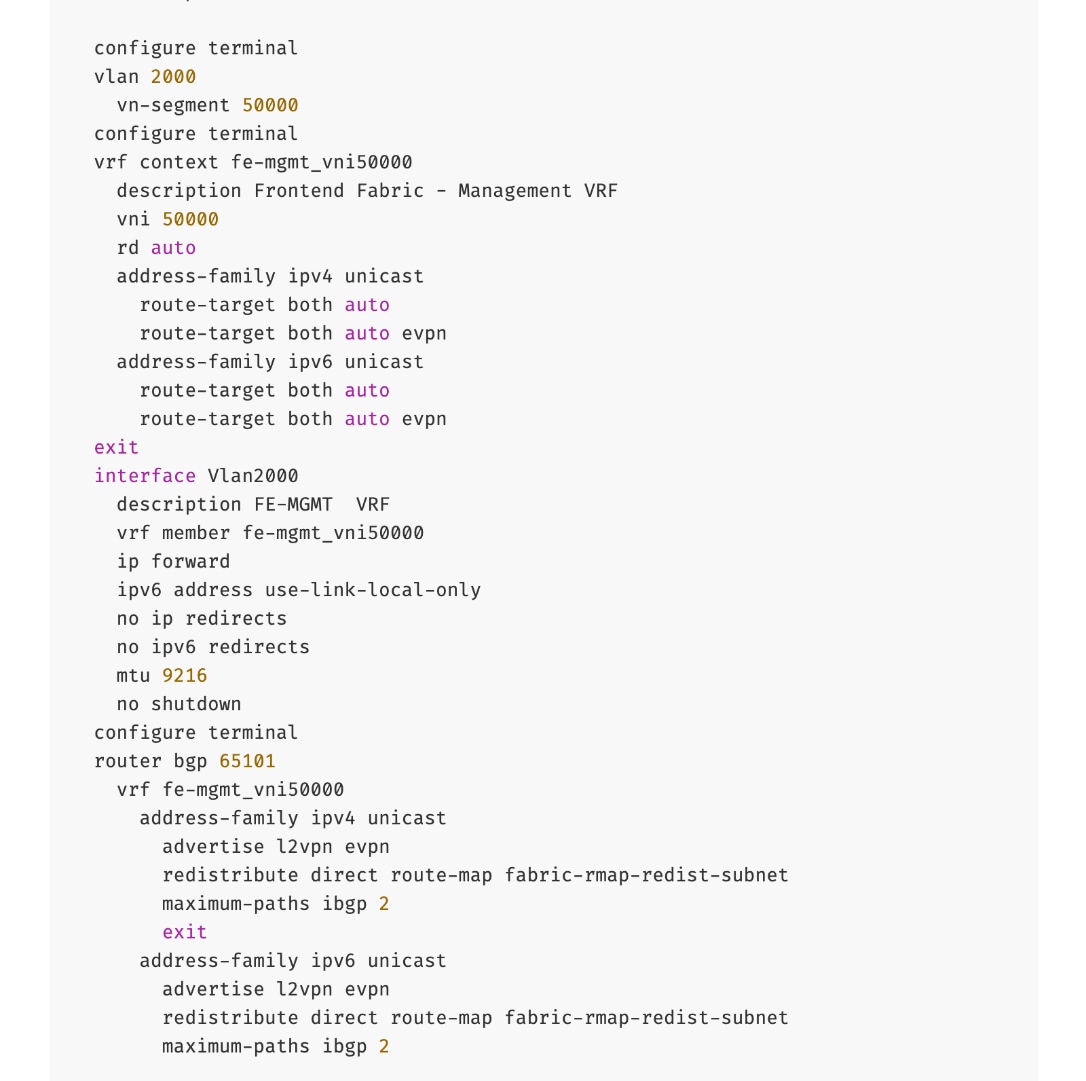
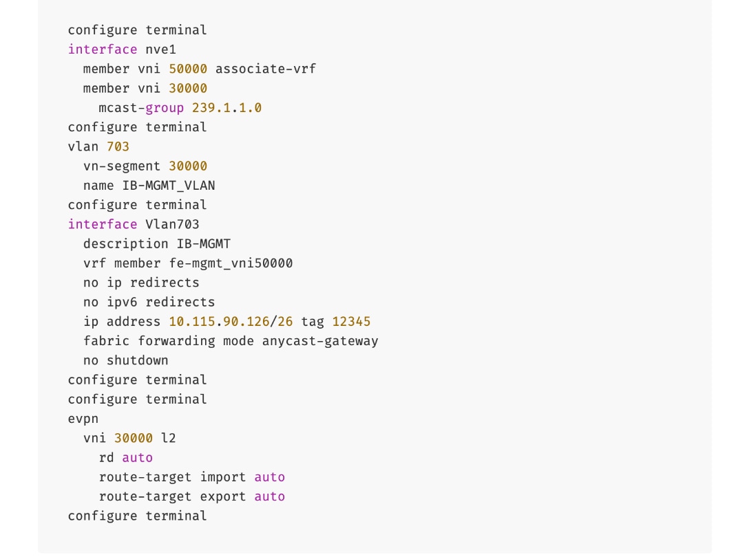
To deploy in-band management connectivity to Management UCS X-Direct on the compute leaf switches in the frontend fabric, follow the procedures below.
Procedure 2. Deploy in-band management connectivity for management UCS X-Direct chassis
Step 1. From a browser, go to Nexus Dashboard. Use the management IP of any node in the ND cluster. Log in using admin account.
Step 2. From the left navigation menu, go to Manage > Fabrics.
Step 3. Select the frontend fabric and go to Segmentation and Security > Networks tab.
Step 4. Select the previously deployed in-band management network from the list.
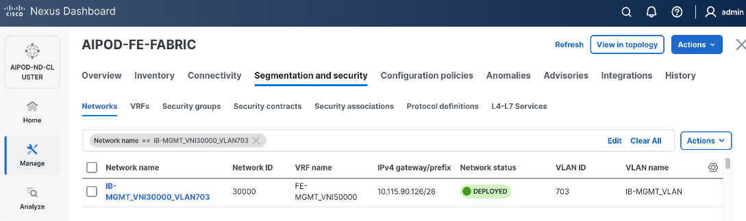
Step 5. Click the lower Actions button and select Multi-attach from the list.
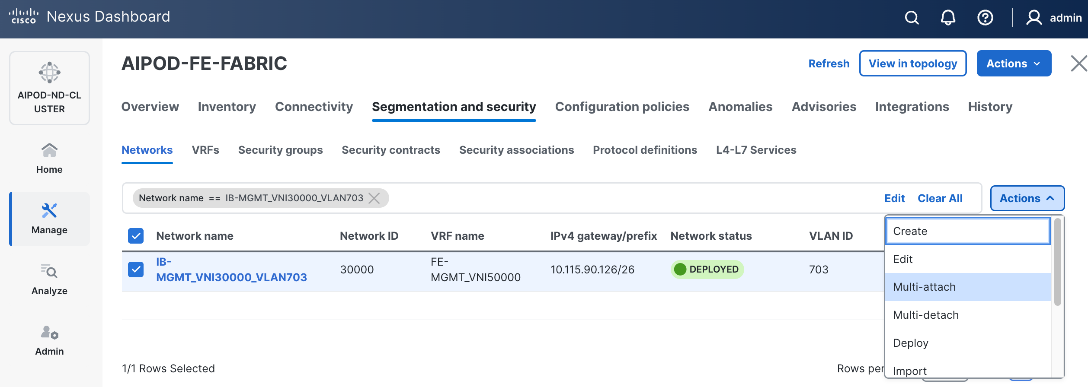
Step 6. Select the leaf switch pair from the list that the UCS X-Direct system connects to.
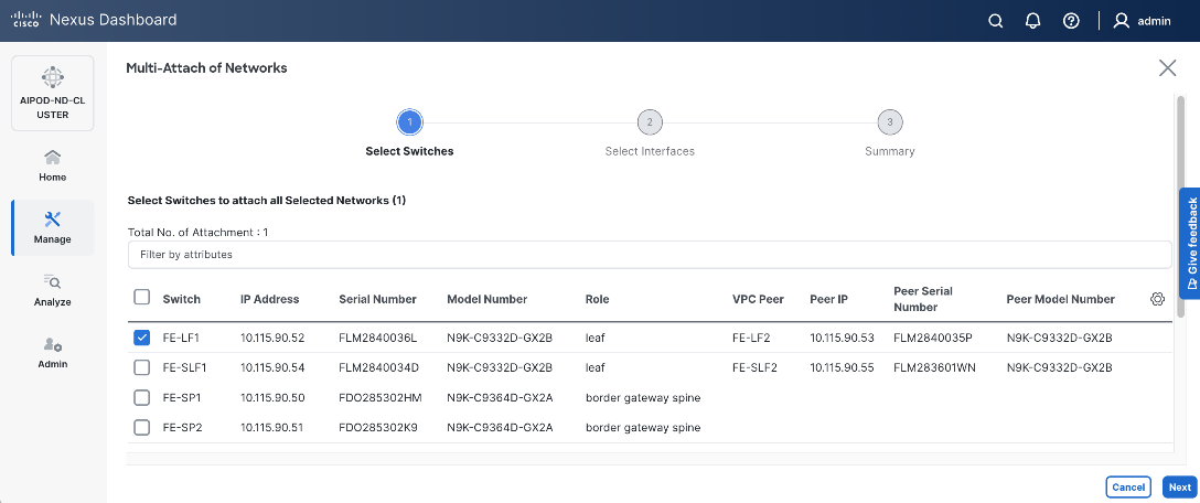
Step 7. Click Next.
Step 8. Click Select Interfaces button to the right of the leaf switch pair to add the interfaces that connect to management UCS X-Direct.
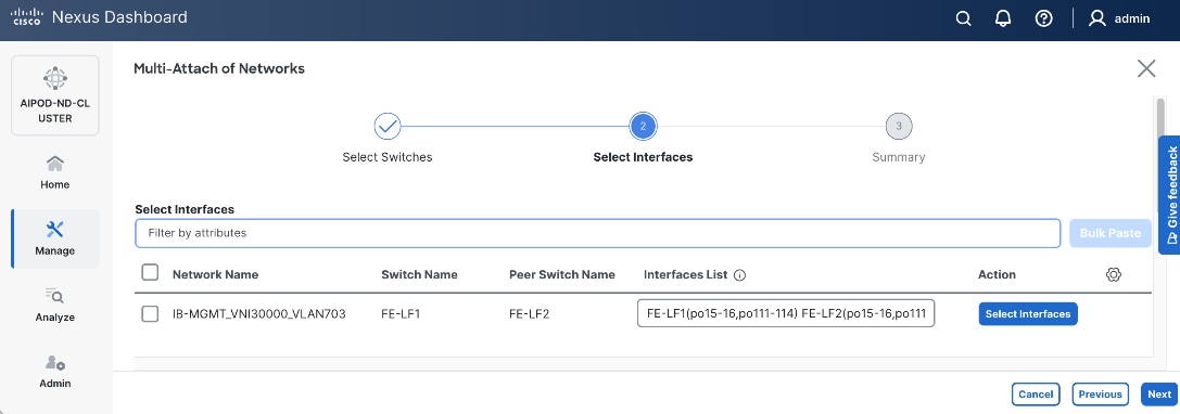
Step 9. Click Next.
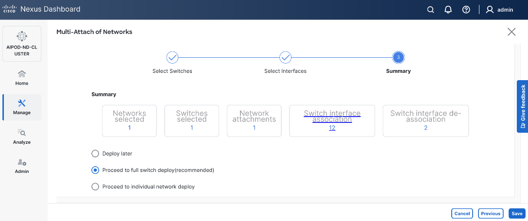
Step 10. Click Save.
Step 11. Click Deploy All.
Step 12. Click Close.
Step 13. Click the Network name to verify that the network was successfully deployed on the relevant switches and interfaces.
Step 14. The configuration deployed on one compute leaf switch is provided below as a reference. For complete switch configs, see solution GitHub repo.
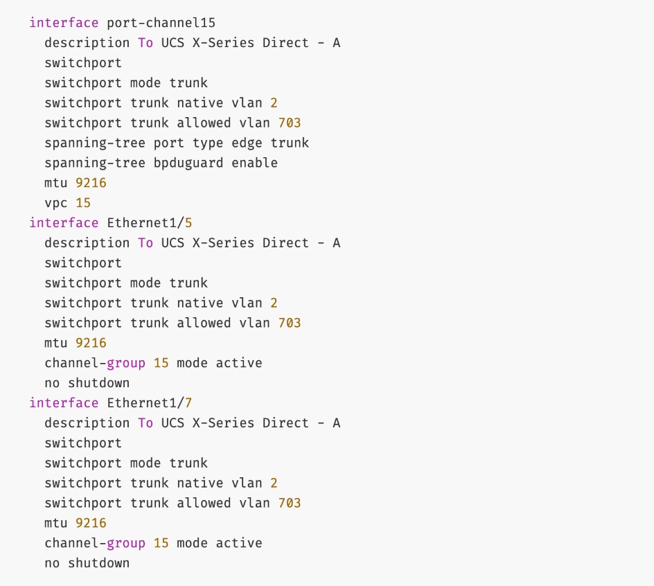
Enable Layer 2 Connectivity to Everpure from FE Fabric
To enable Layer 2 connectivity from the frontend fabric to Everpure FlashBlade, you will configure one vPC on the storage leaf switch pair. The vPC will use two ports on each switch to connect to the first XFM (XFM-1) and two ports to connect to the second XFM (XFM-2). A virtual peer link is used within the frontend fabric, avoiding the need for additional cross-links between storage leaf switches. The detailed connectivity design is shown in Figure 16.
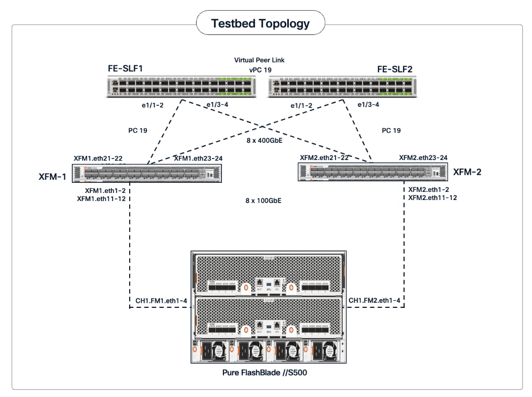
Assumptions and Prerequisites
● Storage leaf switches deployed as a vPC pair
● Everpure XFMs cabled and connect to both storage leaf switches using multiple links
Setup Information
Table 15. Setup Parameters for FE Fabric: Layer 2 Connectivity to Pure FlashBlade//S
| Parameter Type |
Parameter Name | Value |
Parameter Type |
| Leaf Switches |
FE-SLF1, FE-SLF2 |
|
| Everpure FlashBlade |
1 vPCs to both Everpure XFMs |
|
| Virtual Port Channel (vPC) |
To UCS C885As |
UCS GPU Nodes |
| vPC/PC - ID |
19 |
|
| vPC Pair |
FE-SLF1, FE-SLF2 |
|
| Ports |
1/1-2 |
On each Leaf switch (connects to p21-22 on each XFM) |
| Ports |
1/3-4 |
On each Leaf switch (connects to p23-24 on each XFM) |
| VLANs |
|
|
| Pure-NFS_VLAN_3054 |
3054 |
For NFS Storage Data Access |
| Pure-S3-OBJ_VLAN |
570 |
For Object Store Data Access |
Deployment Steps
To enable Layer 2 connectivity from the frontend fabric to Everpure FlashBlade, follow the procedures below.
Procedure 1. Deploy vPC to Everpure FlashBlade
Step 1. From a browser, go to Nexus Dashboard. Use the management IP of any node in the ND cluster. Log in using admin account.
Step 2. From the left navigation menu, go to Manage > Fabrics.
Step 3. Select the frontend fabric and go to Connectivity > Interfaces tab.
Step 4. Click the lower Actions button and select Create interface.
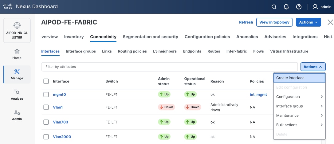
Step 5. In the Create interface window:
● Specify the TypeType of interface as virtual Port Channel (vPC)virtual Port Channel (vPC) from the drop-down list.
● For the Select a vPC pairSelect a vPC pair, select the storagestorage leaf switch VPC pair from the drop-down list.
● Specify a vPC IDvPC ID for the vPC to the Everpure XFMs. Peer-1 and Peer-2 Port-Channel ID should match that of the vPC ID.
● Leave the Policy as int_vpc_trunk_hostint_vpc_trunk_host.
● Enable the checkbox for Config MirroringConfig Mirroring.
● Specify Peer-1 Member InterfacesPeer-1 Member Interfaces that connect to the Everpure XFMs.
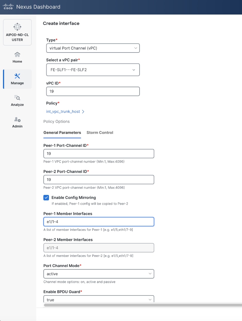
● Specify Peer-1 PO Description.
● EnableEnable checkbox for Copy PO DescriptionCopy PO Description to copy PO description to all member interfaces
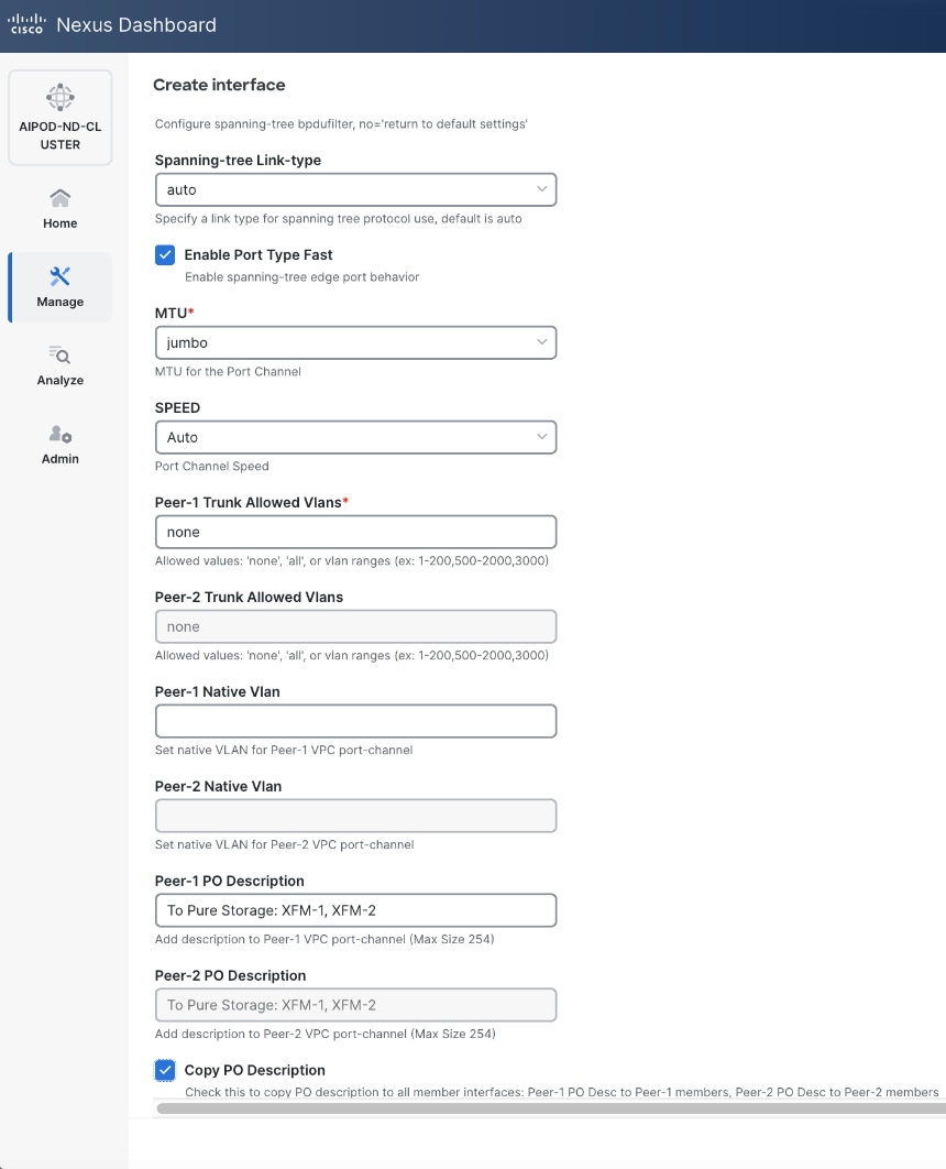
Step 6. Additional configuration changes can be made later as needed. Click Save.
Step 7. Click Preview to view the Pending config changes.
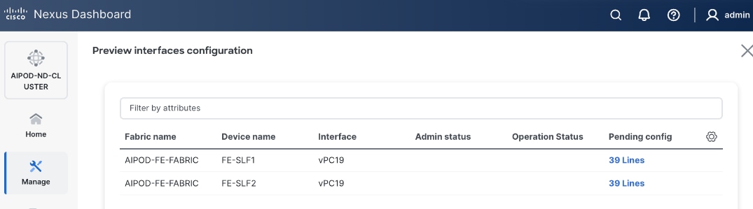
Step 8. Click the Pending Config for each switch to see the configuration.
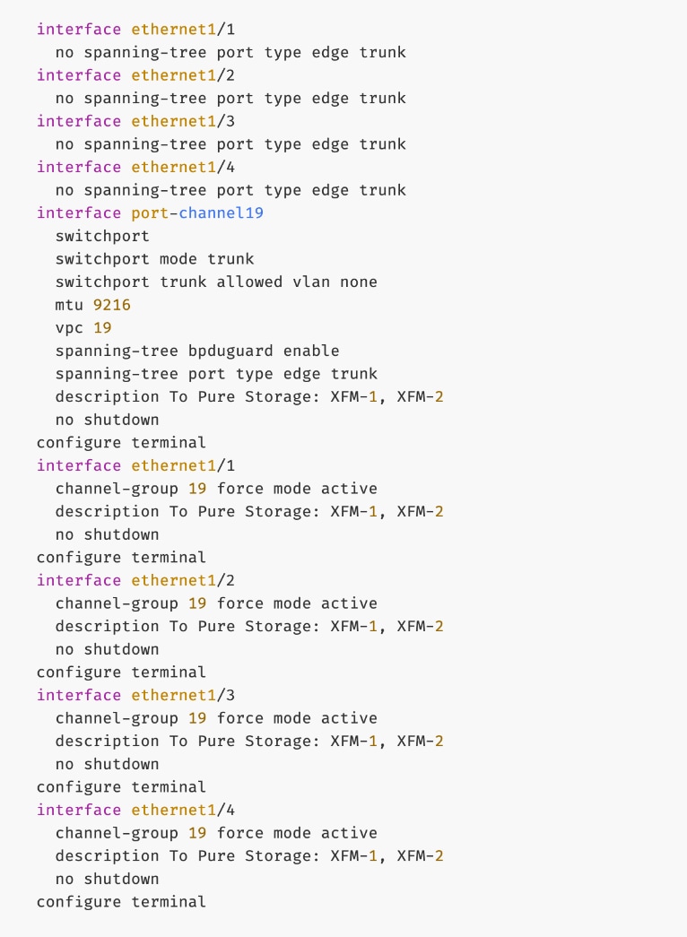
Step 9. Click the X in the top right corner and select Deploy and Deploy config to deploy the Pending config changes.
Step 10. Click Close when deployment completes successfully.
Step 11. Verify that all the interfaces and port-channel is up on each switch in the leaf switch pair that connects to Everpure XFM-1 and XFM-2. It may take a few minutes for the vPC to go from Not discovered to consistent state.
Everpure - Enable NFS Storage Data Access to Everpure FlashBlade//S
Assumptions and Prerequisites
● Layer 2 connectivity in place from frontend fabric to Everpure FlashBlade//S
● Layer 2 connectivity in place from frontend fabric to UCS worker nodes
Setup Information
Table 16. Setup Parameters for FE Fabric: NFS Storage Data Access to Everpure FlashBlade//S
| Parameter Type |
Parameter Name | Value |
Parameter Type |
| NFS Storage Data Network(s) |
|
|
| Name |
Pure-NFS_VNI_33054 |
|
| Layer 2 Only |
Enable checkbox |
|
| Network ID |
33054 |
|
| VLAN ID |
3054 |
|
| VLAN Name |
Pure-NFS_VLAN_3054 |
|
| Interface Description |
Pure-NFS |
|
|
|
|
|
| Everpure FlashBlade |
|
|
| Leaf Switch Pair |
FE-SLF1, FE-SLF2 |
|
| vPC |
19 |
|
| Port Channel |
19 |
Members: e1/1-4 |
| Leaf Switch Pair |
FE-LF1, FE-LF2 |
|
| vPC |
15,16, 111-114 |
To Management UCS-X Direct, UCS C885A GPU Nodes |
| Port Channel |
15,16, 111-114 |
Members: e1/1-4 |
Deployment Steps
To enable NFS storage data access from the frontend fabric to Everpure FlashBlade, follow the procedures below using the setup information provided in this section.
Procedure 1. Enable NFS Storage Data Access to Everpure FlashBlade
Step 1. From a browser, go to Nexus Dashboard. Use the management IP of any node in the ND cluster. Log in using admin account.
Step 2. From the left navigation menu, go to Manage > Fabrics.
Step 3. Select the frontend fabric and go to Segmentation and Security > Networks tab.
Step 4. Click the lower Actions button and select Create from the menu.
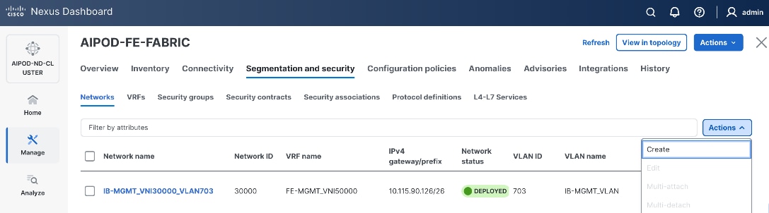
Step 5. In the Create Network window, specify the following:
● Network name
● Enable checkbox for Layer 2 only Layer 2 only.
● Network IDNetwork ID or use default.
● VLAN ID VLAN ID or click Propose VLAN Propose VLAN button to let system define a VLAN.
● In the General Parameters tab, specify VLAN Name and Interface Description.
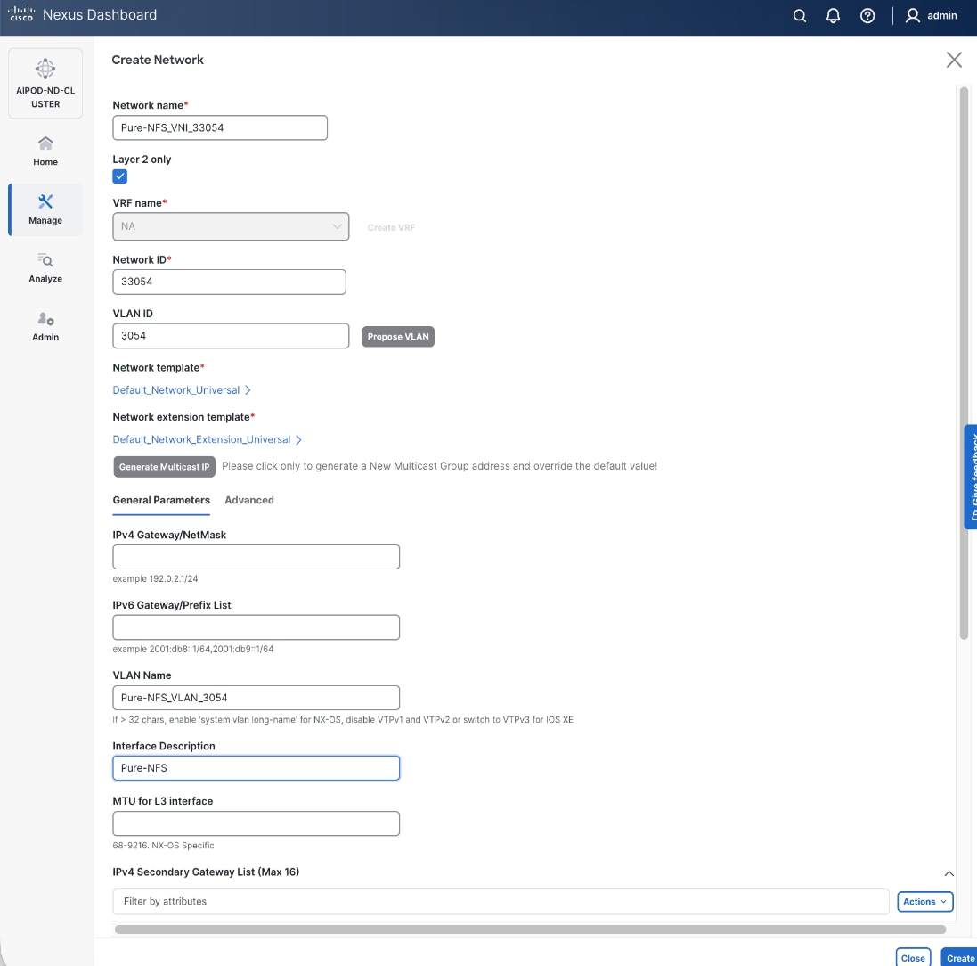
Step 6. Click Create to create the NFS Storage Data Network.
Step 7. Select the newly created network. Click the lower Actions button and select Multi-attach from the list.
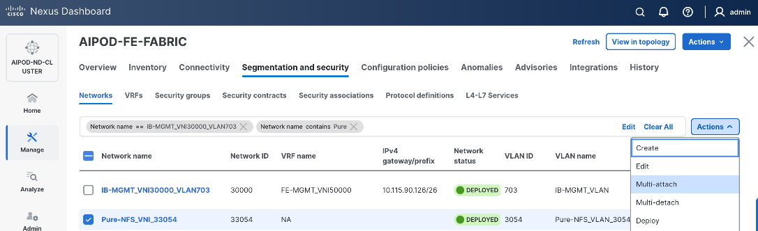
Step 8. Select the compute and storage Leaf switch pairs.
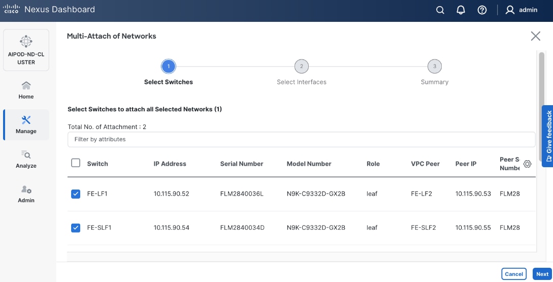
Step 9. Click Next.
Step 10. Select the Network Name and the first leaf pair to add the network to from the list.
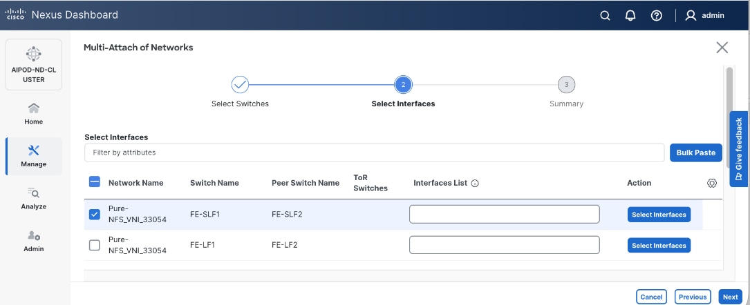
Step 11. Click Select interfaces button on the right to deploy this network as a trunked VLAN on the selected interfaces.
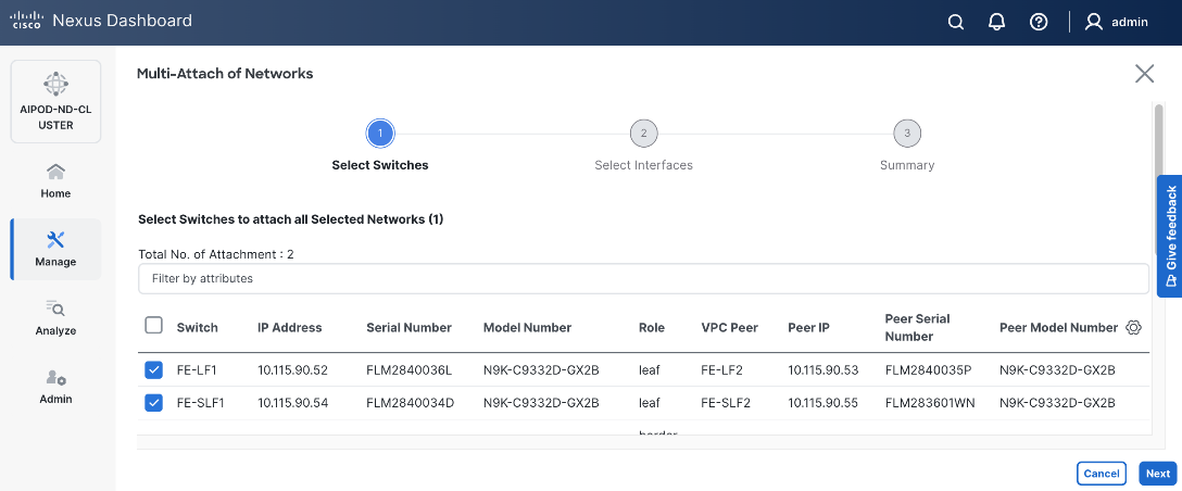
Step 12. Click Save.
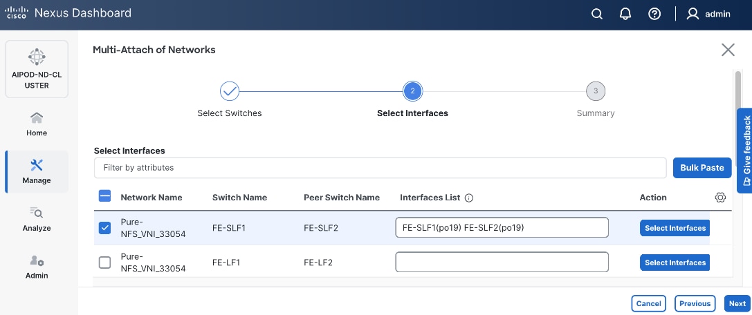
Step 13. Repeat steps 1 - 12 to add the same network to the second leaf pair interfaces. The interfaces in this case will be to UCS compute nodes that will access NFS storage on Everpure FlashBlade. Additional interfaces can be added later as needed.
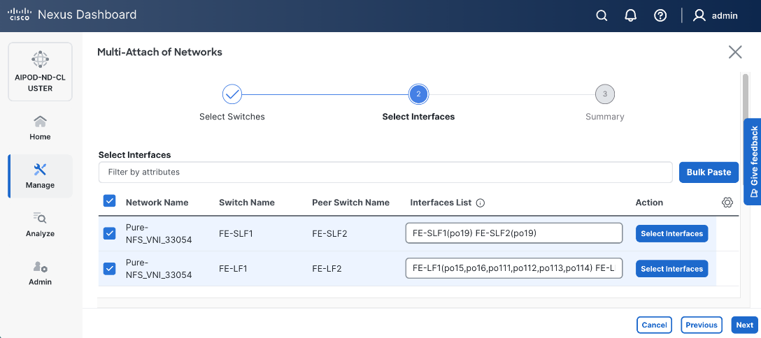
Step 14. Click Next.
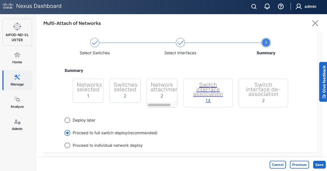
Step 15. Click Save.
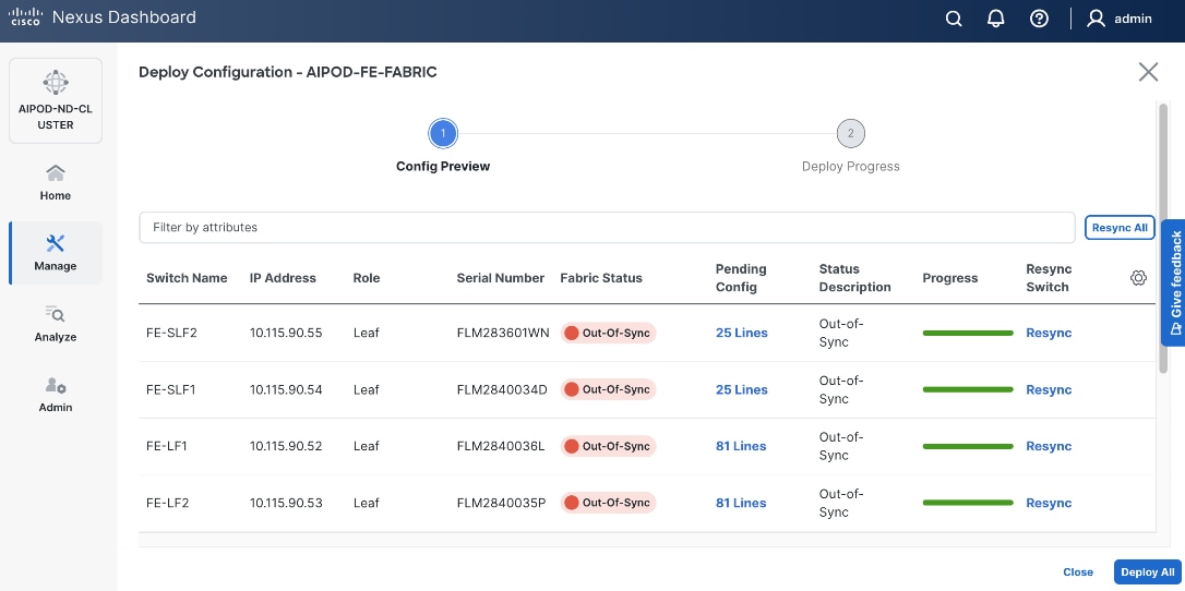
Step 16. Click Pending Config to see the configuration being deployed. The pending configuration from one leaf switch is provided as a reference at the end.
Step 17. Click Deploy All.
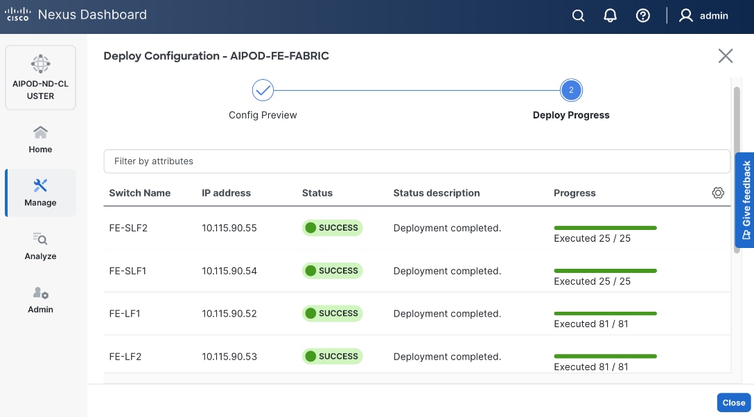
Step 18. Click Close.
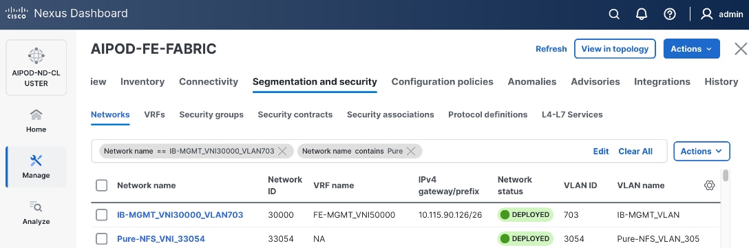
Step 19. Click the Network name to verify that the network was successfully deployed on the relevant switches and interfaces.
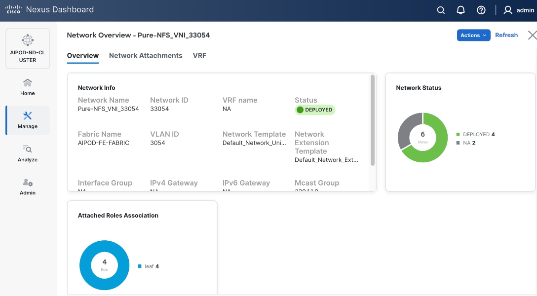
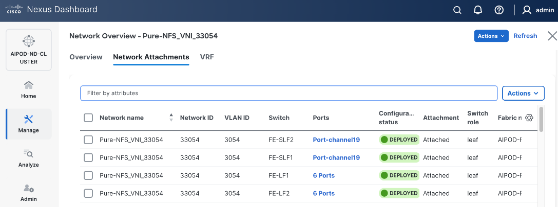
Step 20. The configuration deployed on one storage and compute leaf switch is provided below as a reference. For complete switch configs, see solution GitHub repo.
● Storage LeafStorage Leaf – Deployed Configuration
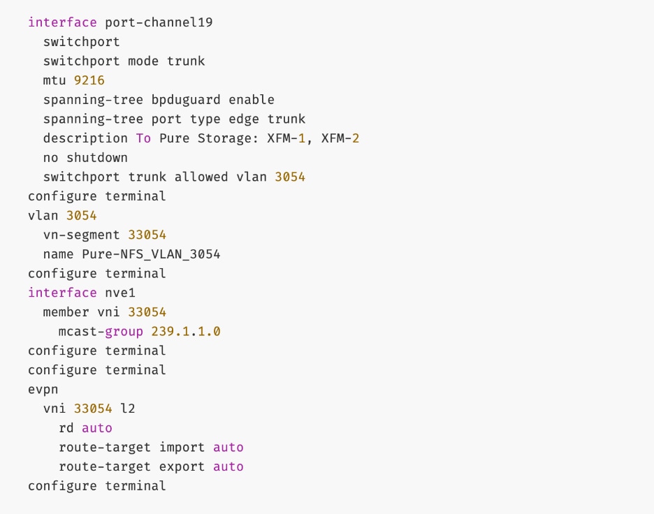
● ComputeCompute LeafLeaf – Deployed Configuration
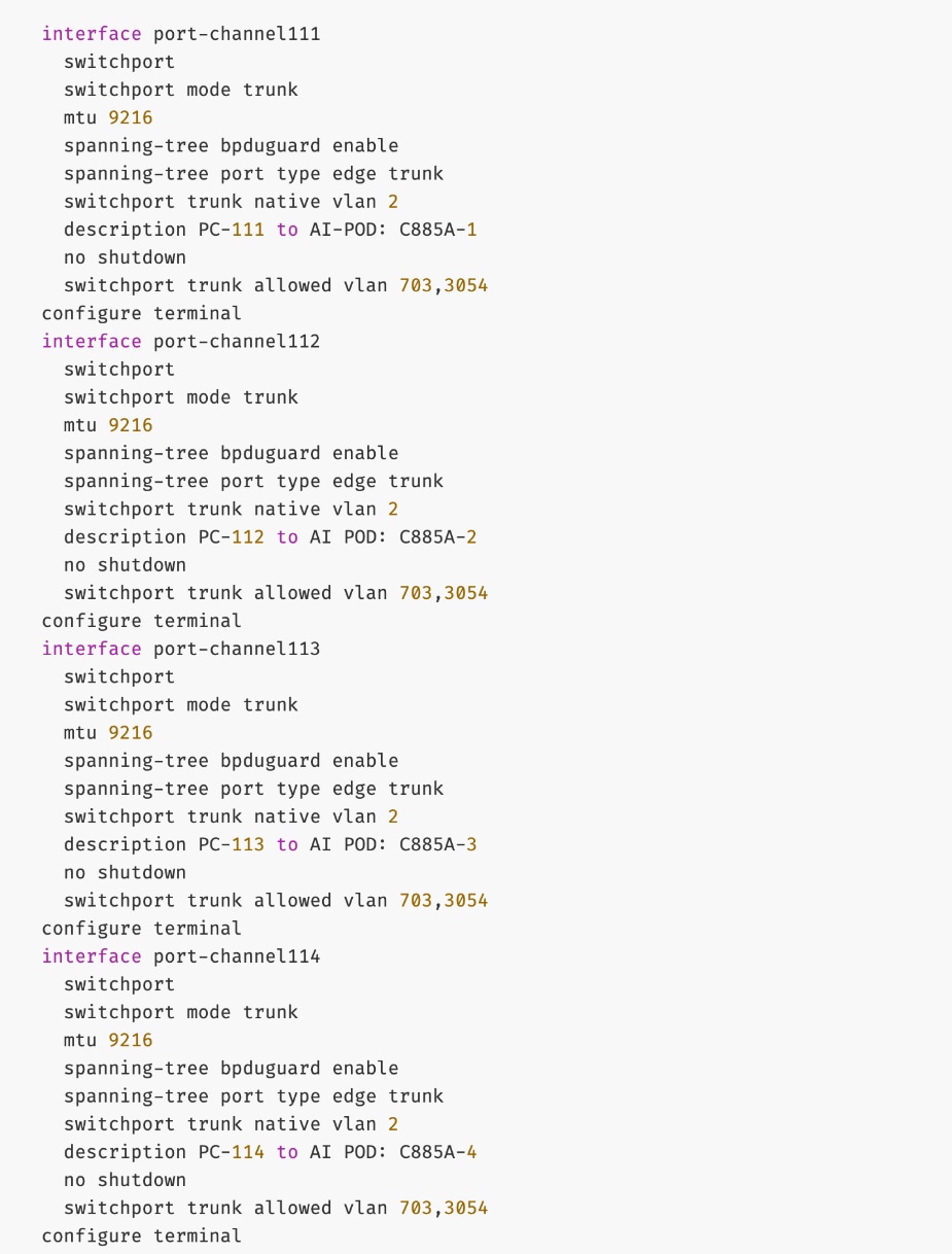
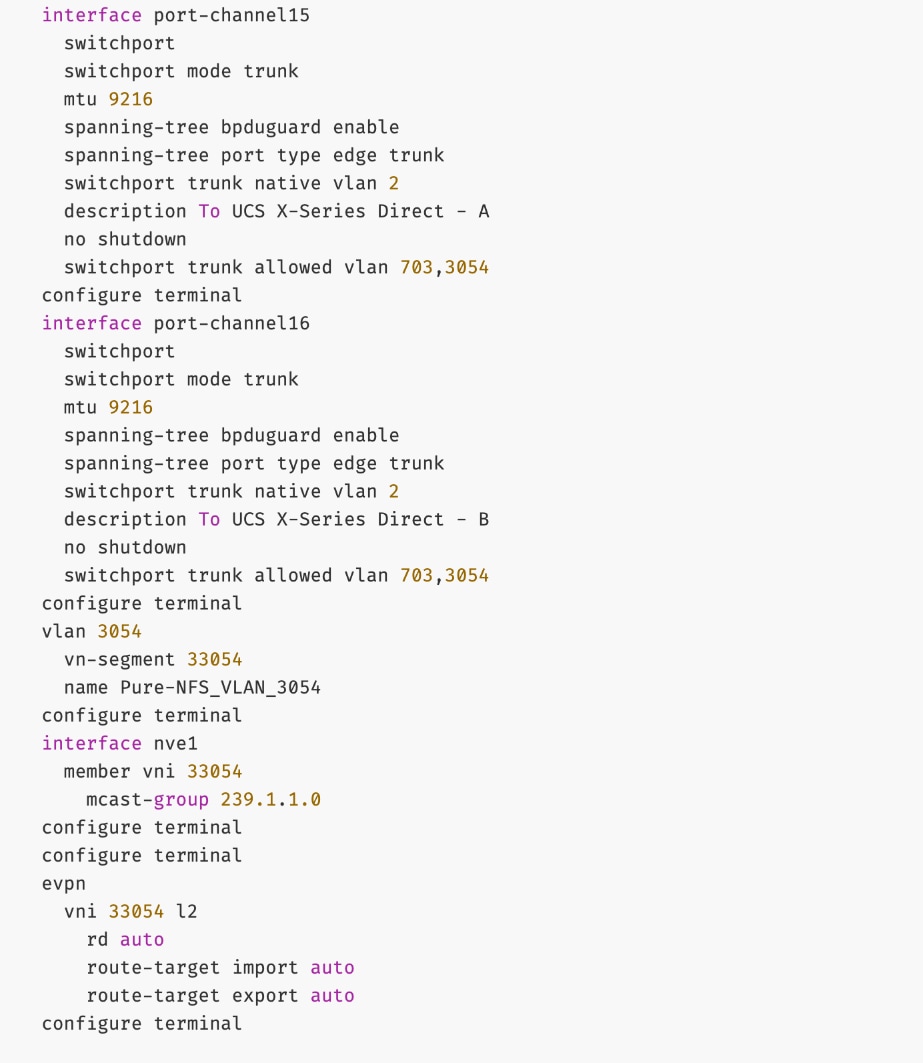
Everpure - Enable S3-compatible Object Store Data Access to Everpure FlashBlade//S
Assumptions and Prerequisites
● Layer 2 connectivity in place from frontend fabric to Everpure FlashBlade//S
● In-Band management connectivity to UCS worker nodes in place
Setup Information
Table 17. Setup Parameters for FE Fabric: Object Store Data Access to Everpure FlashBlade//S
| Parameter Type |
Parameter Name | Value |
Parameter Type |
| Object Store Data Network(s) |
|
|
| Name |
Pure-S3-OBJ_VNI_30570 |
|
| Layer 2 Only |
No |
|
| IB-MGMT VRF |
|
|
| VRF Name |
FE-MGMT_VN50000 |
|
| VRF ID |
50000 |
(System Proposed) |
| VLAN ID |
2000 |
(System Proposed) |
| VRF Interface Description |
FE-MGMT VRF |
|
| VRF Description |
Frontend Fabric – Management VRF |
|
| S3-OBJ Network |
|
|
| Network ID |
30570 |
Network ID |
| VLAN ID |
570 |
VLAN ID |
| IPv4 Gateway/Netmask |
10.115.90.214/29 |
|
| VLAN Name |
Pure-S3-OBJ_VLAN |
|
| Interface Description |
Pure-S3-OBJ |
|
| Everpure FlashBlade |
|
|
| Leaf Switch Pair |
FE-SLF1, FE-SLF2 |
|
| vPC |
19 |
|
| Port Channel |
19 |
Members: e1/1-4 |
Deployment Steps
To enable S3-compatible object store data access to Everpure FlashBlade//S, complete the following steps.
Procedure 1. Enable S3-compatible object store date access
Step 1. From a browser, go to Nexus Dashboard. Use the management IP of any node in the ND cluster. Log in using admin account.
Step 2. From the left navigation menu, go to Manage > Fabrics.
Step 3. Select the frontend fabric and go to Segmentation and Security > Networks tab.
Step 4. Click the lower Actions button and select Create from the menu.
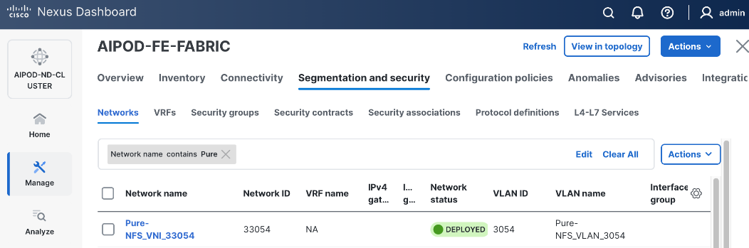
Step 5. In the Create Network window, specify the following:
● Network name
● VRF name VRF name – select the previously deployed VRF from the drop-down list.
● Network IDNetwork ID or use default.
● VLAN ID VLAN ID or click Propose VLAN Propose VLAN button to let system define a VLAN.
● In the General Parameters tab, specify IP Gateway/NetmaskIP Gateway/Netmask, VLAN NameVLAN Name, and Interface DescriptionInterface Description.
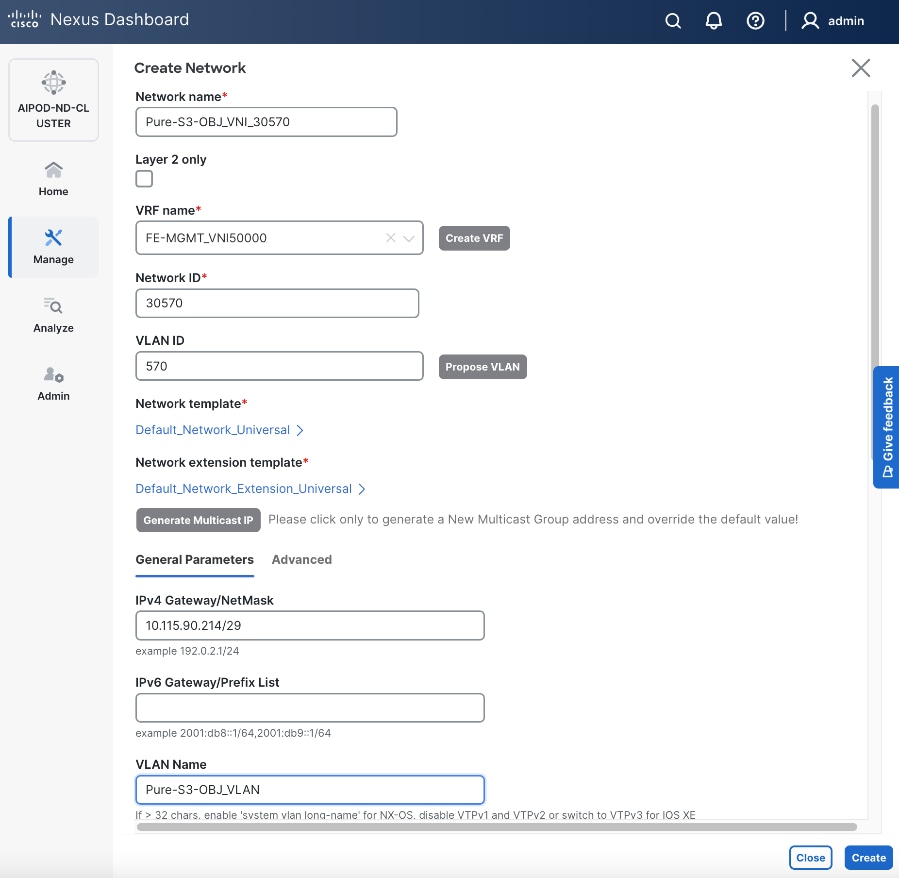
Step 6. Click Create to create the Object Store Data Network.
Step 7. Select the newly created network.
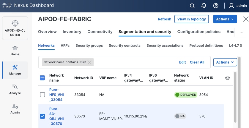
Step 8. Click the lower Actions button and select Multi-attach from the list.
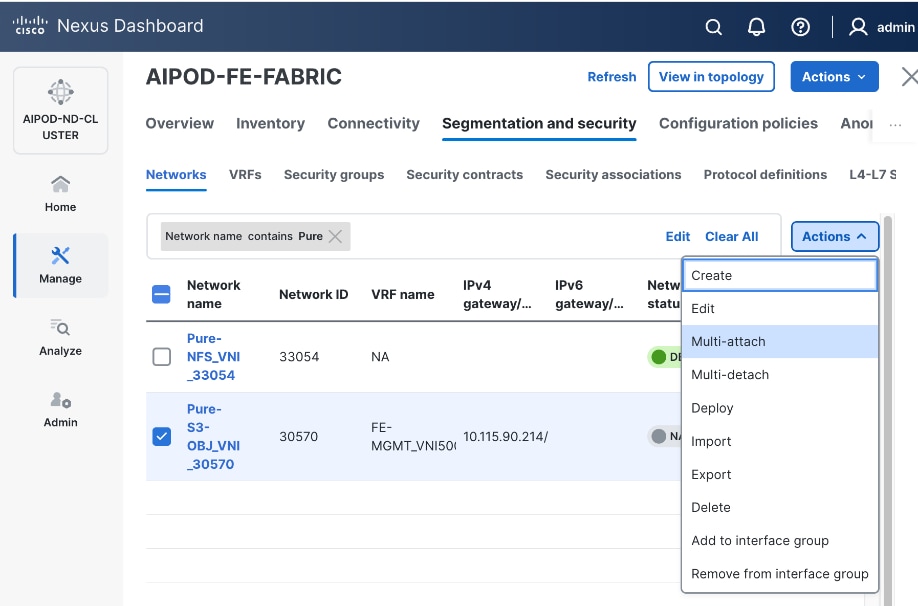
Step 9. Select the storage Leaf switch pairs.
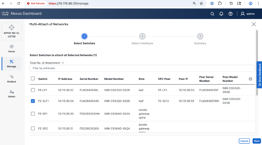
Step 10. Click Next.
Step 11. Select the Network Name associated with storage leaf pair to add the network to from the list.
Step 12. Click Select interfaces on the right of the Network Name to deploy this network as a trunked VLAN on the selected interface(s).
Step 13. Click Save.
Step 14. Click Next.
Step 15. Click Save.
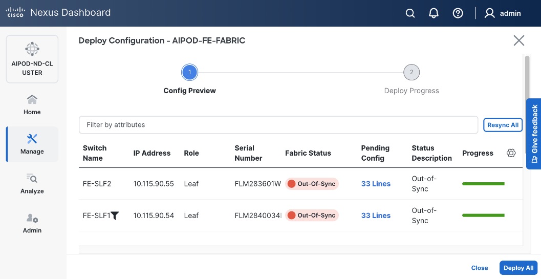
Step 16. Click Pending Config to see the configuration being deployed. The pending configuration from one leaf switch is provided below as a reference.
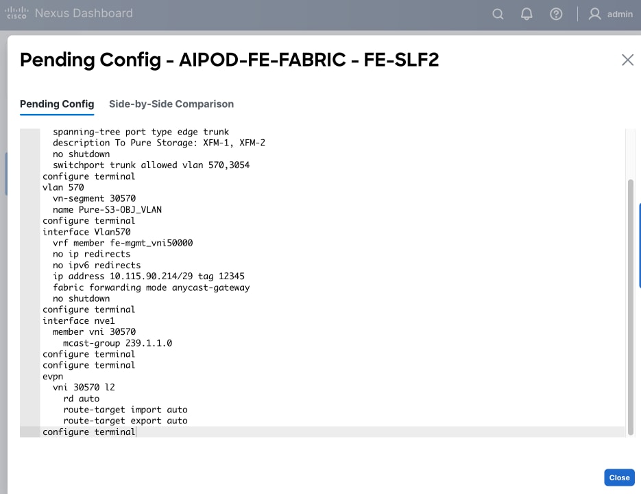
Step 17. Click Close or X in the top right corner to close.
Step 18. Click Deploy All.
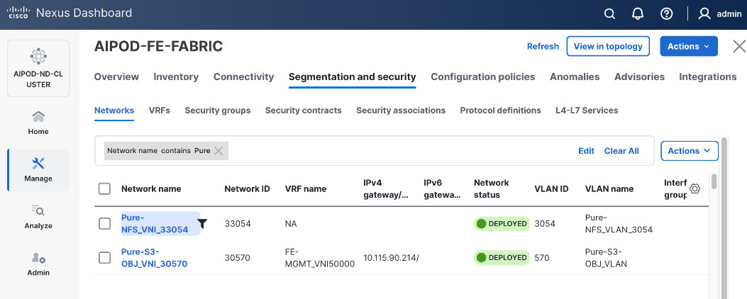
Step 19. Click Close.
Step 20. Click the Network name to verify that the network was successfully deployed on the relevant switches and interfaces.
Enable External Connectivity from Frontend Fabric
This is a placeholder to enable external connectivity to access SaaS services such as Cisco Intersight and Red Hat Hybrid Cloud Console that will be required later to complete the setup. External connectivity will depend on the organization’s existing policies and therefore the configuration for this is outside the scope of this CVD. However, the configuration used in this CVD setup is included in the Nexus switch configurations provided in the AI POD GitHub repo – this access is provided via the Spine switches in the setup, serving as Border Gateways to the rest of the enterprise and external networks.
Enable QoS for Frontend Fabric
To provide low-latency, lossless RDMA connectivity for storage data access using either NFS over RDMA and GPUDirect Storage, a QoS policy is deployed in the frontend fabric as detailed in this section.
Assumptions and Prerequisites
Frontend fabric has been deployed and setup.
Setup Information
Table 18. Setup Parameters for FE Fabric: QoS
| Parameter Type |
Parameter Name | Value |
Parameter Type |
| Modified QoS Policy |
|
|
| Name |
AIPOD-FE-QOS-200G |
|
| Priority Flow Control (PFC) MTU |
9216 |
Default = 4200 |
| Fabric Settings |
|
|
| AI QoS and Queueing Policies |
Enable |
Checkbox |
| AI QoS and Queueing Policy |
AIPOD-FE-QOS-200G |
Select modified policy from drop-down list |
| Interface Settings |
|
|
| Priority Flow Control |
Enable |
Checkbox |
| QoS |
Enable |
Checkbox |
Deployment Steps
To deploy QoS on the frontend fabric, follow the procedure below.
Procedure 1. Modify default QoS policy for FE fabric
Step 1. From a browser, go to Nexus Dashboard. Use the management IP of any node in the ND cluster. Log in using admin account.
Step 2. From the left navigation menu, go to Manage > Template Library.
Step 3. Use Filter to view all templates that contain QOS in the name.
Step 4. Select the AI_Fabric_QoS_100G policy.
Step 5. Click the lower Actions button and select Duplicate template from the menu.
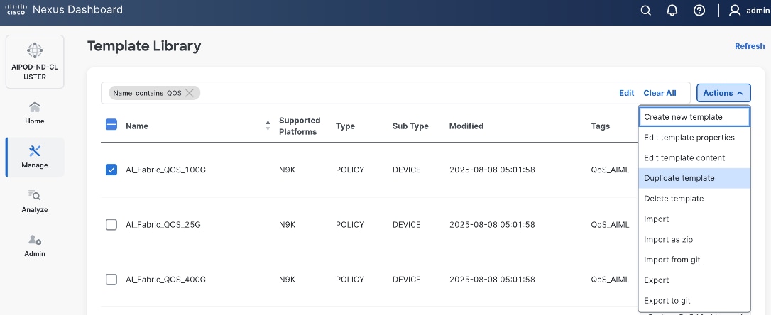
Step 6. For Template Properties, specify a Template Name for the new template. Adjust the Description as needed.
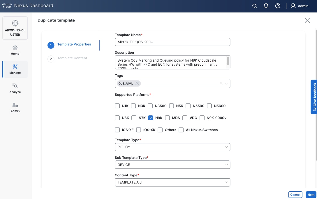
Step 7. Click Next.
Step 8. For Template Content, scroll down to policy-map type network-qos qos_network, and change the MTU for PFC from 4200 to default of 9216 as shown below.
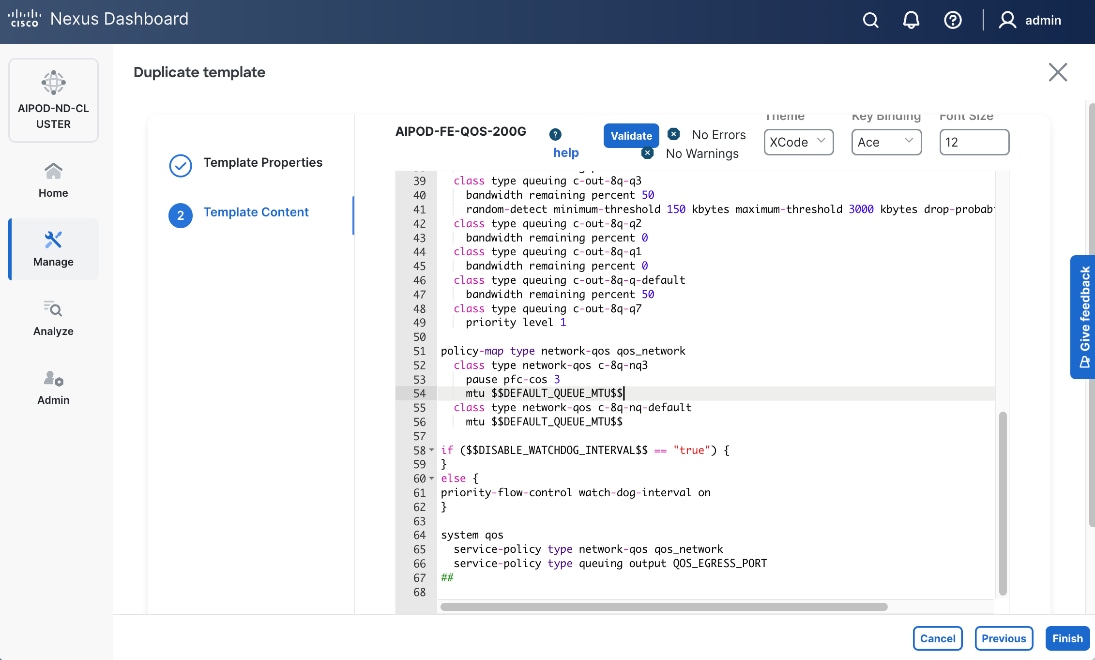
Step 9. Click Finish.
Procedure 2. Deploy modified QoS policy in Frontend Fabric
Step 1. From a browser, go to Nexus Dashboard. Use the management IP of any node in the ND cluster. Log in using admin account
Step 2. From the left navigation menu, go to Manage > Fabrics.
Step 3. Select the frontend fabric.
Step 4. Click the upper Actions button and select Edit fabric settings.
Step 5. Go to Fabric management > Advanced.
Step 6. Scroll down and enable the checkbox for Enable AI QoS and Queuing Policies.
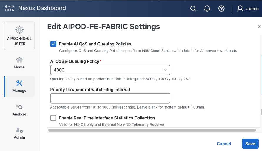
Step 7. For AI QoS & Queuing Policy, select the modified QoS policy from the drop-down list.
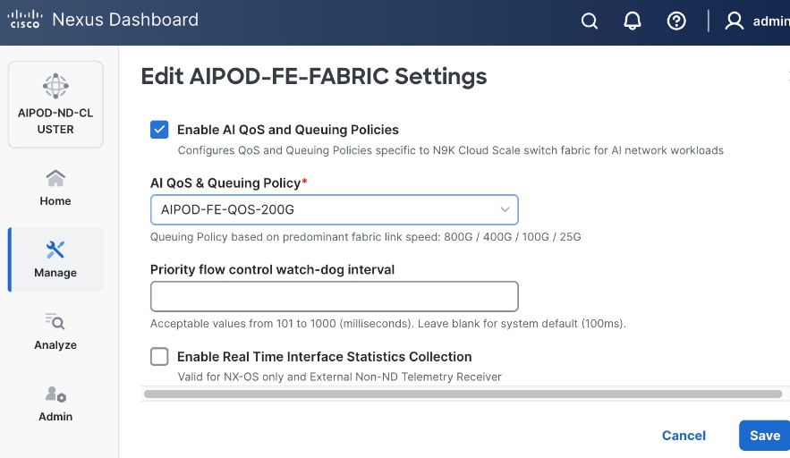
Step 8. Click Save.
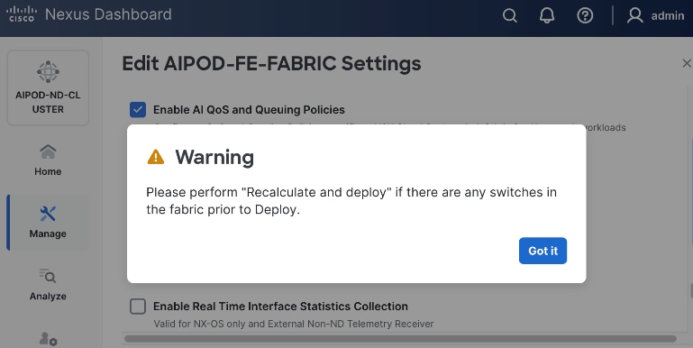
Step 9. In the pop-up window, review the warning and click Got It.
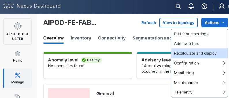
Step 10. Click the upper Actions button and select Recalculate and deploy from the menu.
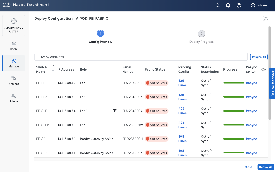
Step 11. Click Deploy All.
Step 12. Click Close.
Procedure 3. Enable Priority Flow Control on interfaces
Step 1. From a browser, go to Nexus Dashboard. Use the management IP of any node in the ND cluster. Log in using admin account.
Step 2. From the left navigation menu, go to Manage > Fabrics.
Step 3. Select the frontend fabric and go to Connectivity > Interfaces.
Step 4. Select the first interface and click the lower Actions button and select Edit interface.
Step 5. Scroll down to the bottom and enable the following QoS related settings.
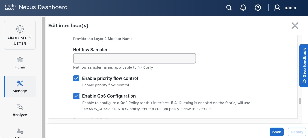
Step 6. Click Save.
Step 7. Click Deploy.
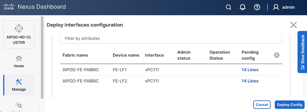
Step 8. Click Pending config to see configuration that will be deployed on the interface on each switch.
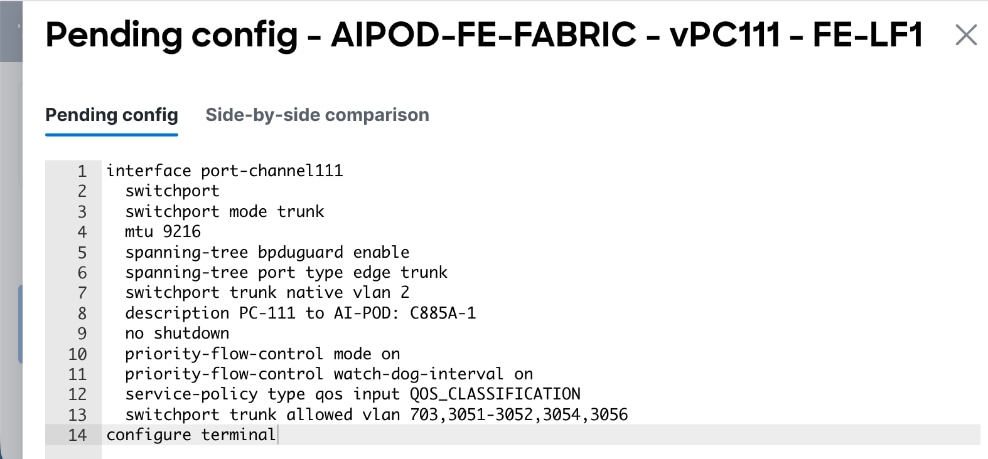
Step 9. Click Deploy Config.
Step 10. Repeat this procedure for all remaining interfaces on both leaf switches access the storage system.
Deploy Backend Fabric using Nexus Dashboard
The procedures detailed in this section use Cisco Nexus Dashboard, specifically the fabric templates provided by ND, to deploy the backend fabric in the AI POD solution. This fabric is a 2-tier, 3-stage spine-leaf Clos topology, built using Cisco Nexus 9000 series data center switches. Once the fabric is deployed, ND will be used to provision GPU-to-GPU connectivity between UCS GPU nodes in the AI POD training cluster. The UCS GPU nodes will using the backend (E-W) NICs to connect to the backend fabric.
The procedures in this section:
● Deploy a VXLAN EVPN fabric using Nexus Dashboard templates. The backend leaf and spine switches are connected in a 2-tier spine-leaf topology
● Modify default QoS policies to support AI training workloads
● Enable GPU-to-GPU networking between UCS GPU nodes across the backend fabric
Deploy VXLAN EVPN Fabric using Nexus Dashboard Templates
Assumptions and Prerequisites
● Nexus Dashboard cluster deployed
● All switches in the backend fabric cabled in a spine-leaf topology
● Reachability from ND cluster to switches so that they can be discovered and added to the fabric
Setup Information
Table 19. Setup Information for BE Fabric
| Parameter Type |
Parameter Name | Value |
Parameter Type / Other Info |
| Fabric Template |
|
|
| Fabric Type |
AI > AI VXLAN Fabric |
Radio button |
| Settings |
|
|
| Configuration Mode |
Default |
Radio button |
| Fabric Name |
AIPOD- BE-Fabric |
|
| Location |
Raleigh, US |
Dropdown list |
| BGP ASN |
65200 |
Select a value from private ASN range (64512 – 65535), different from that used on the FE fabric |
| Licensing tier for fabric |
Premier |
Radio button |
| Enable Features |
Telemetry |
Radio button |
| Add Switches without Reload |
enable |
Fabric Management > Advanced |
| Switch Discovery |
|
|
| Seed IP |
<specify> |
|
| Authentication/Privacy |
MD5 |
Other options available |
| Username and Password |
<specify> |
|
| Max Hops |
1 |
|
| Preserve Config |
Disable Checkbox |
This will remove the config on the switch when it is added to the fabric |
| Switch Role |
See next table |
|
In this setup, the Nexus Backend Fabric consisted of 2 spine and 2 leaf switches. The fabric switch details are listed in Table 20.
Table 20. Setup Information for BE Fabric: Fabric Switch Details
| Switch |
Role |
OOB IP |
Firmware |
Model |
| BE-LF1 |
Leaf |
10.115.90.58 |
10.4(5) |
Cisco Nexus 9332D-GX2B |
| BE-LF2 |
Leaf |
10.115.90.59 |
10.4(5) |
Cisco Nexus 9332D-GX2B |
| BE-SP1 |
Spine |
10.115.90.60 |
10.4(5) |
Cisco Nexus 9364D-GX2A |
| BE-SP2 |
Spine |
10.115.90.61 |
10.4(5) |
Cisco Nexus 9364D-GX2A |
Deployment Steps
To deploy the backend fabric, follow the procedures below using the setup information provided above.
Procedure 1. Deploy BE Fabric using Nexus Dashboard Template
Step 1. From a browser, go to Cisco Nexus Dashboard. Use the management IP of any node in the ND cluster. Log in using admin account.
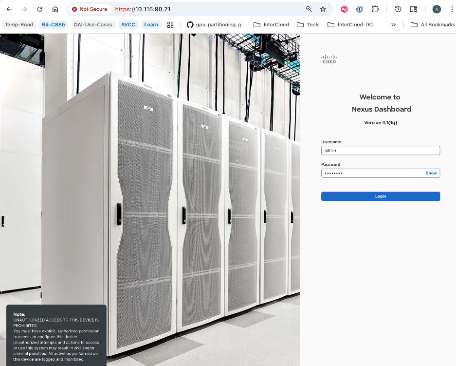
Step 2. Go to Manage > Fabrics.
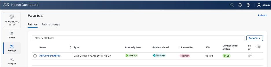
Step 3. Click Actions.
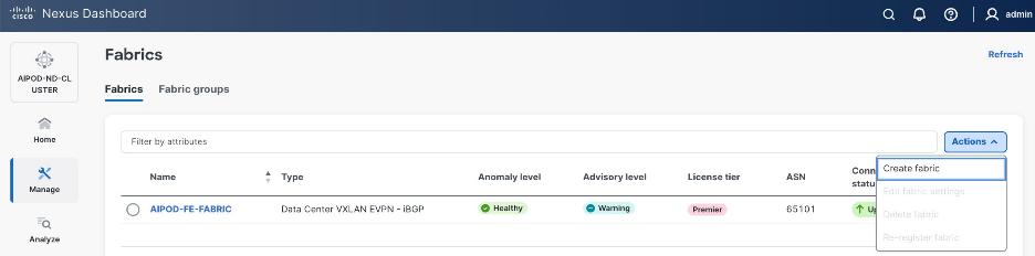
Step 4. Select Create Fabric from the drop-down list.
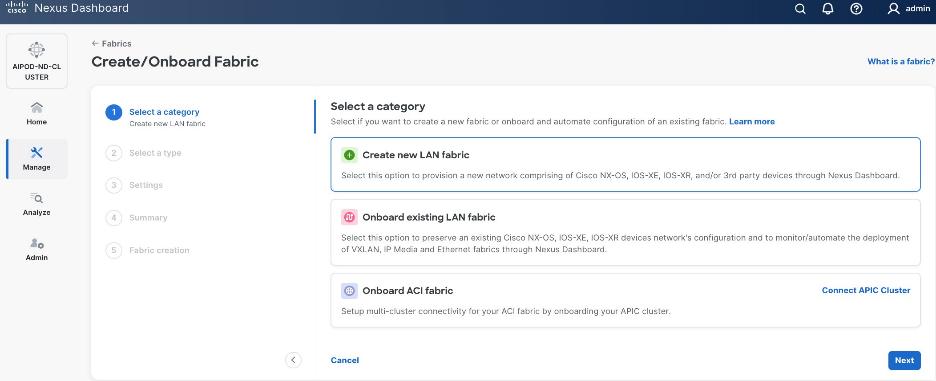
Step 5. Select Create a new LAN fabric. Click Next.
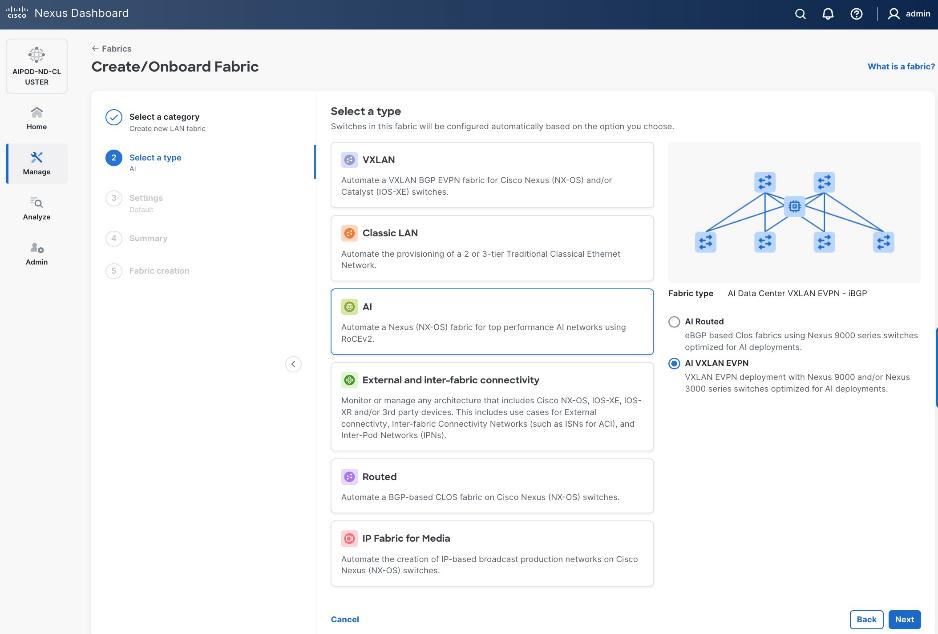
Step 6. For the Backend (E-W) AI/ML fabric, go to AI > AI VXLAN EVPN to manage and setup a high-speed 400GbE fabric for GPU-to-GPU connectivity. Click Next.
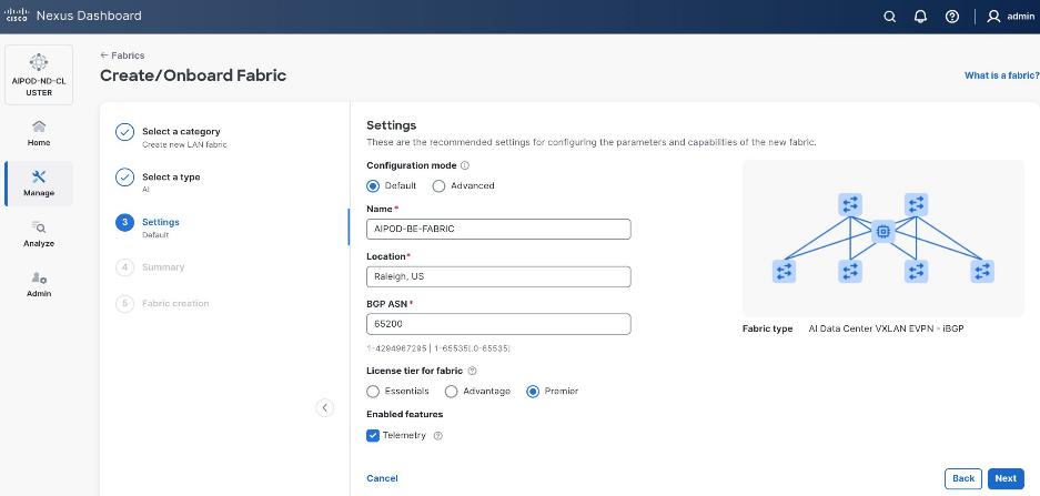
Step 7. To configure the backend fabric, under Configuration Mode, specify the following:
● Leave the radio button enabled for Default.
● Specify Name, Location, and BGP ASN (from the private ASN range: 64512 – 65535).
● Select a Licensing tier for the BE fabric - see "?" icon to get more details on the available options.
● (Optional) Enable Telemetry feature.
Step 8. Enable the radio button for Advanced in the Configuration Mode section to see additional configuration options for the fabric.
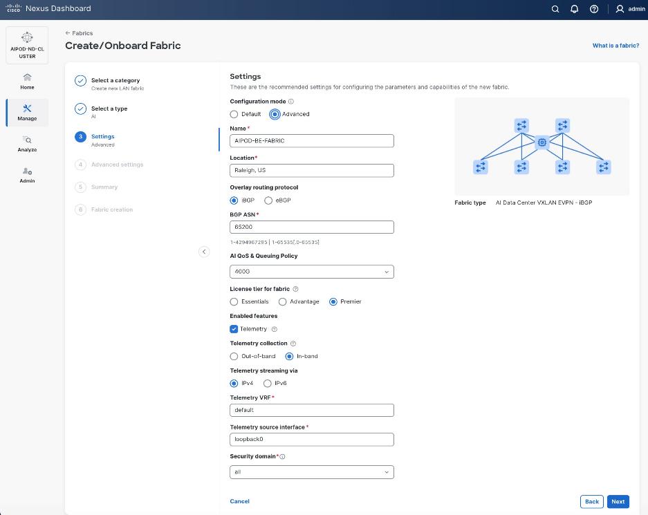
Step 9. Verify QoS and Telemetry settings. Adjust as needed for your setup. Click Next.
Step 10. In the Advanced Settings menu, select the Resource tab. Note that the ND provided IP addressing scheme is in place for the underlay.
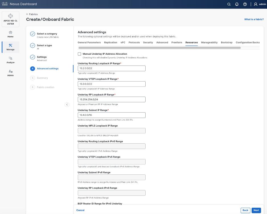
Step 11. Change the IP address for this fabric from the default values to prevent overlap with frontend fabric, also managed by the same Nexus Dashboard.
Note: For this CVD validation, the first octet was changed from 10 to 20. The backend fabric is isolated from other networks with no external connectivity so the addressing could be kept the same as frontend, but the Nexus dashboard will generate alerts and warnings to indicate this overlap so changing it to avoid this.
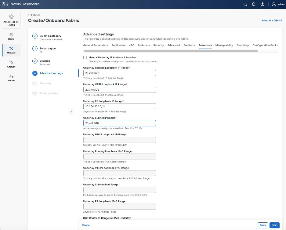
Step 12. Scroll down and change the VRF Lite Subnet IP Range. Click Next.
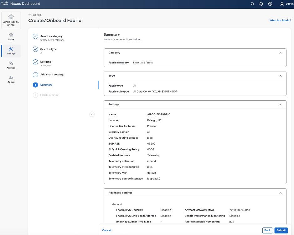
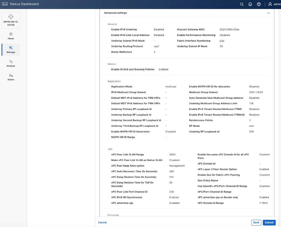
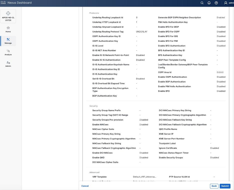
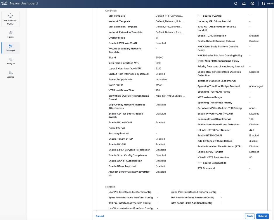
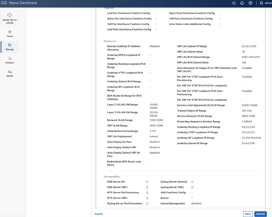
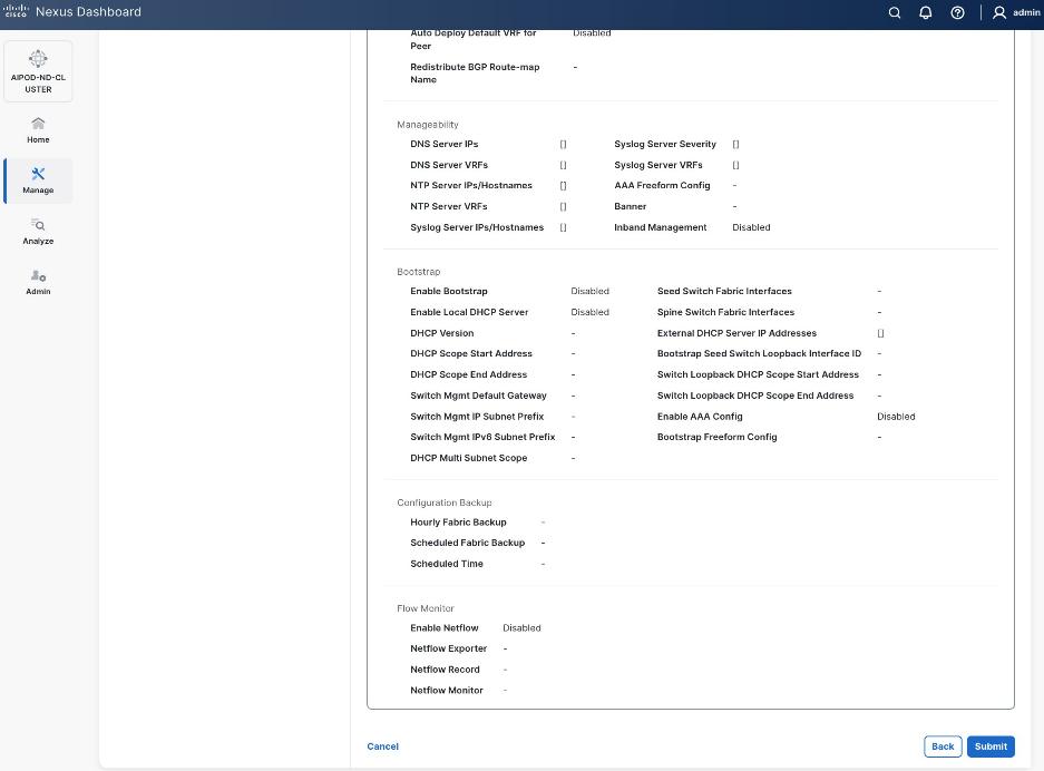
Step 13. Review the Fabric Summary settings.
Step 14. Click Submit.
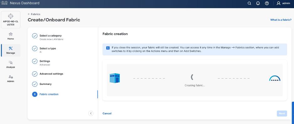
Step 15. Wait for the Fabric creation to complete.
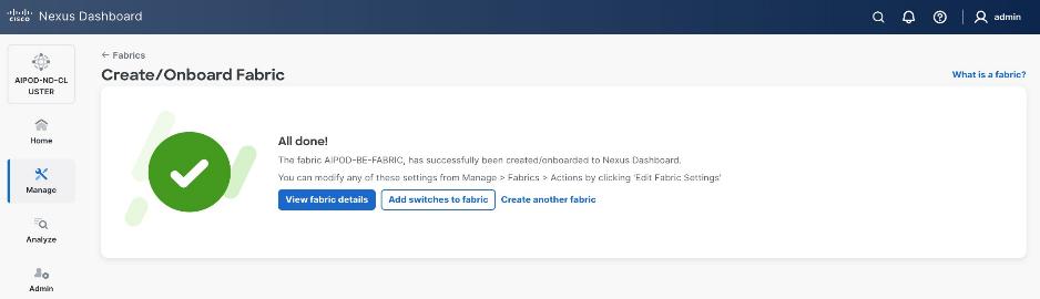
Step 16. Click View fabric details to see the dashboard for the newly created backend fabric.
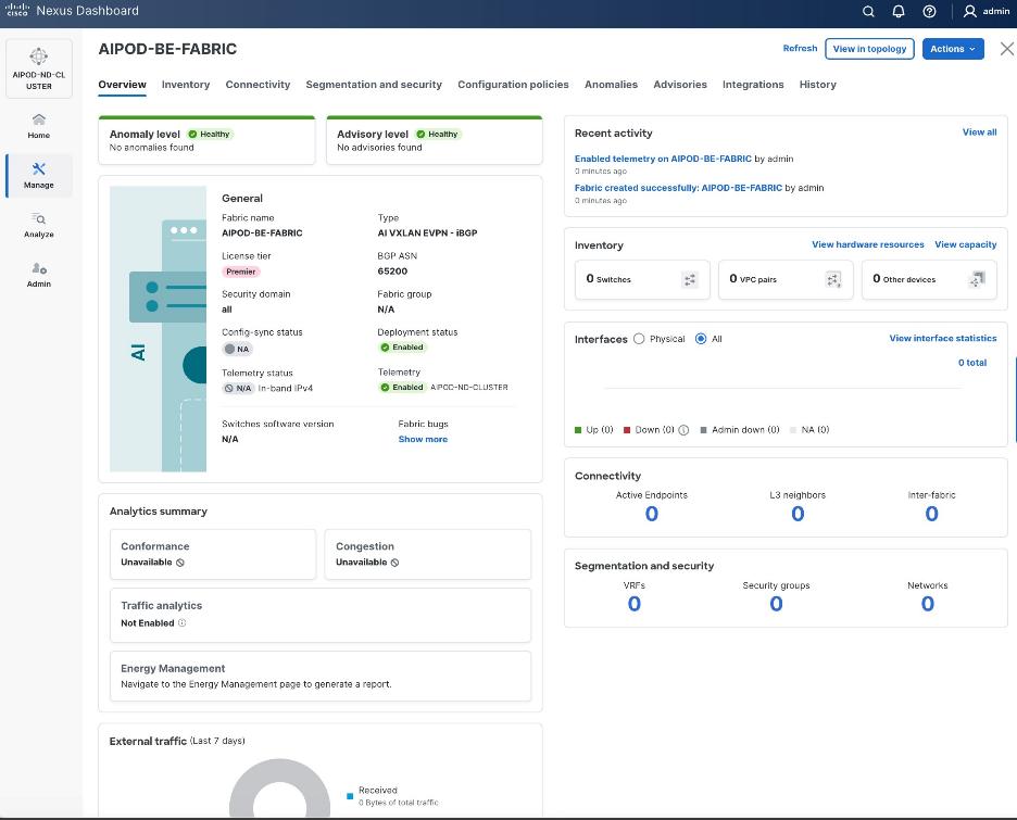
Procedure 2. (Optional) Disable reload of switches added to the BE fabric
Step 1. By default, any switches added to the fabric will go through a reload. To add switches without a reload, go to Manage > Fabrics.
Step 2. Select the radio button for the backend fabric deployed earlier.
Step 3. From the Actions menu, select Edit Fabric Settings.
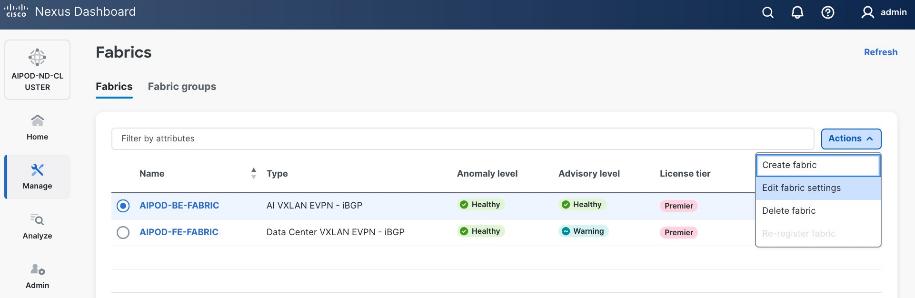
Step 4. Select Fabric Management > Advanced tabs and scroll down to find the field for Add switches without Reload. Select enable from the drop-down list. Click Save.
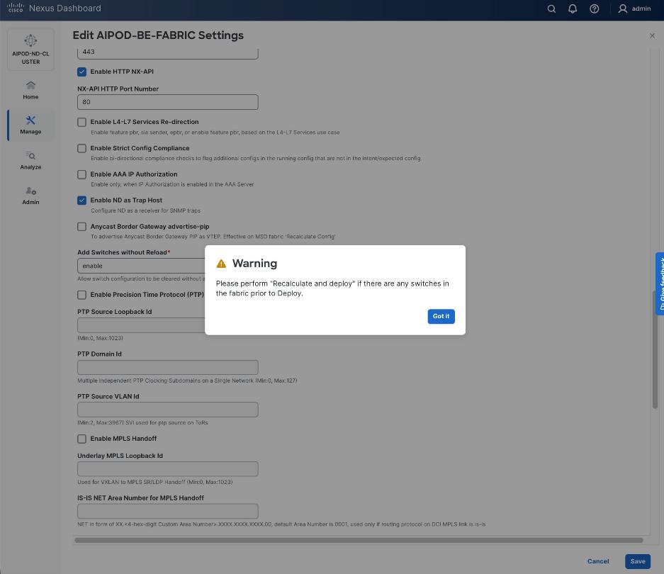
Step 5. In the pop-up Warning window, review the message and click Got it.
Procedure 3. Discover and add Spine and Leaf switches to the BE Fabric
Step 1. From the Manage > Fabrics view, click the backend fabric name to add switches to the fabric.
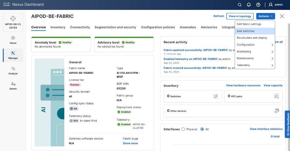
Step 2. Click Actions > Add switches. Specify the following:
● Seed IP
● Authentication/Privacy
● Username and Password
● Max Hops
● Uncheck Preserve Config
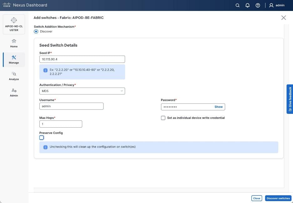
Step 3. Click Discover Switches.
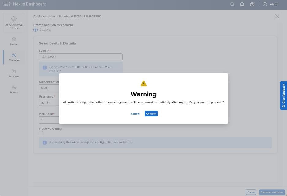
Step 4. Click Confirm. Filter the discovered switch list to view just the switches you want to add.

Step 5. Click Add Switches.
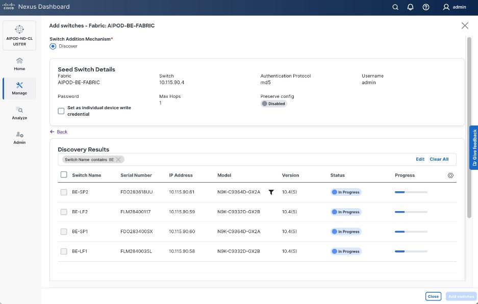
Step 6. When the Status changes from In Progress to Switch Added, click Close.
Procedure 4. Verify/change role for switches added to the BE fabric
Step 1. From the left navigation menu, select Manage > Fabrics and select the backend fabric from the list. From the fabric view, click the Inventory > Switches tab.
Step 2. For each switch in the list, verify Role is correct. To change the role, select the switch and then click Actions and select Set role from the drop-down list.
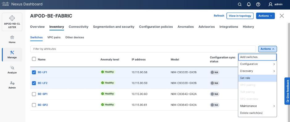
Step 3. In the Select Role pop-up window, select the correct role from the list and click Select.
Step 4. Click OK in the pop-up window with the warning to perform Recalculate and deploy to apply the change.
Step 5. Repeat steps 1 – 4 to change the role for other switches in the fabric.
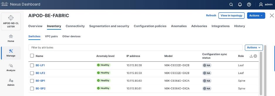
Step 6. Click the upper Actions button and select Recalculate and deploy from the drop-down list. If it says one is already in progress, wait a few minutes and repeat the steps.
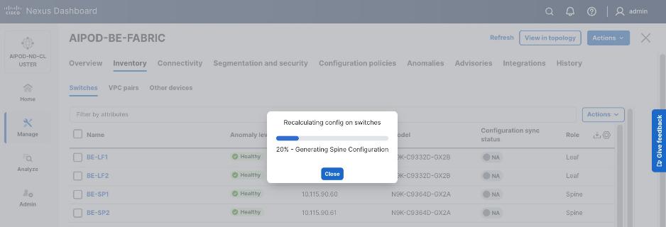
Step 7. You should see the Fabric as Out-of-sync with a count for lines of config. in the Pending Config column based on the above recalculation.
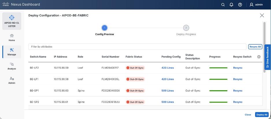
Step 8. To view the exact changes that will be deployed on each switch, click the lines of config in the Pending Config column for that switch. Click Close.
Step 9. Click Deploy All.
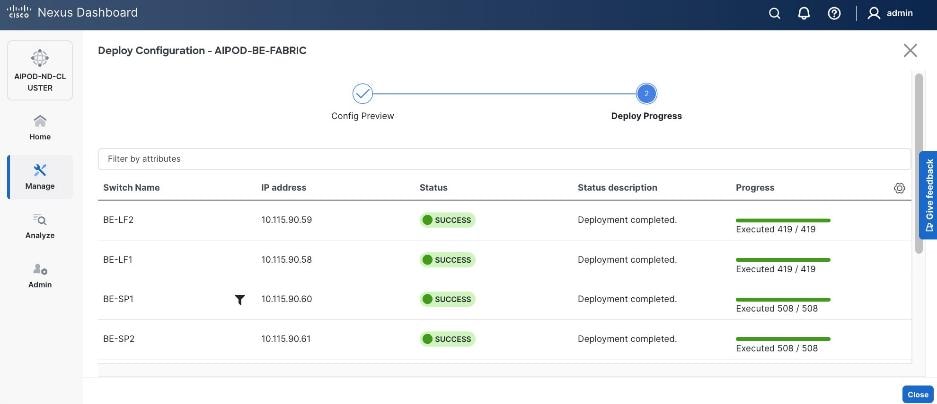
Step 10. When the configuration deployment completes successfully, click Close.
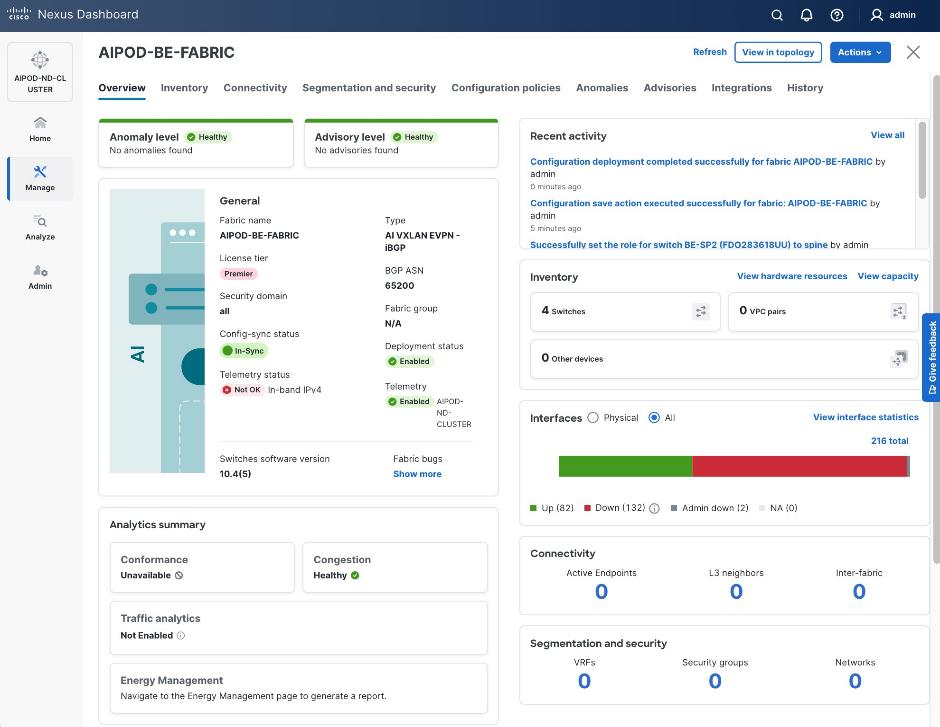
Procedure 5. Review fabric state and upgrade software as needed
Step 1. ND may identify issues in hardware, connectivity, software and so on, reflected by the Anomaly level. To view the flagged anomalies, go to Anomalies in the top menu bar. Address each anomaly to prevent issues later, either by resolving them or acknowledging them.
Step 2. Review the Advisories and resolve or acknowledge them.
Step 3. Evaluate and upgrade to the most current Cisco recommended Nexus OS release.
The backend fabric is now ready to connect to the UCS GPU nodes to enable GPU-to-GPU communication across the backend fabric.
Modify QoS Policy on backend fabric
This procedures in this section will modify the default QoS policy deployed by the AI/ML fabric template used to deploy and configure the backend fabric.
Assumptions and Prerequisites
● Backend VXLAN fabric deployed
● AI Fabric template with default QoS policy enabled
Table 21. Setup Information for BE Fabric QoS
| Parameter Type |
Parameter Name | Value |
Parameter Type / Other Info |
| QoS Policy Template |
|
|
| Default/Original Policy Template Name |
400G | AI_Fabric_QOS_400G |
|
| New Policy Template Name |
AIPOD-BE-QOS-400G |
|
| PFC MTU |
9216 |
Default for this release: 4200 |
| Bandwidth Percent for ‘c-out-8q-q3’ |
90 |
Default = 50 |
| Bandwidth Percent for ‘c-out-8q-q-default’ |
90 |
Default = 50 |
Deployment Steps
To change the QoS policy deployed in the backend fabric, follow the procedures below using the setup information provided in this section.
Procedure 1. Create new template from default QoS policy template
Step 1. From a browser, go to Cisco Nexus Dashboard. Use the management IP of any node in the ND cluster. Log in using admin account.
Step 2. Go to Manage > Template Library.
Step 3. Filter on QOS in the top search bar.
Step 4. Select the default QoS policy that was applied when the backend fabric was deployed using the default AI fabric template.
Step 5. Click Actions.
Step 6. Select Duplicate template from the drop-down list.
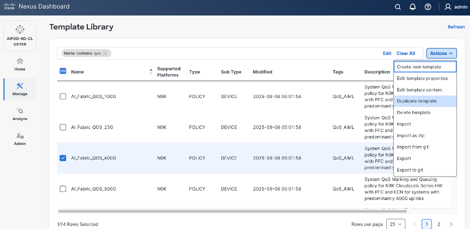
Step 7. In the Template Properties section, specify a new name for the QoS policy template.
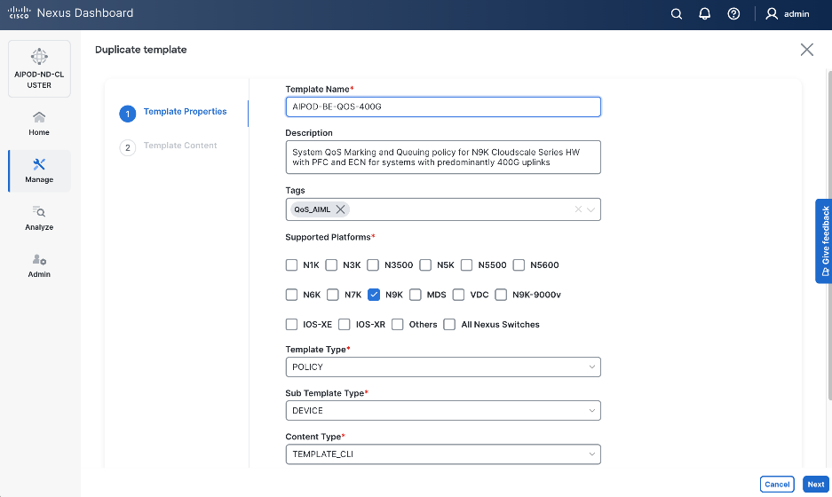
Step 8. In the Template Content section, modify the bandwidth percent for two queues: c-out-8q-q3 to 90 and c-out-8q-q to 10. Also, scroll down and change PFC MTU to 9216.
Note: Bandwidth Percent for the above queues can be adjusted as needed for your environment.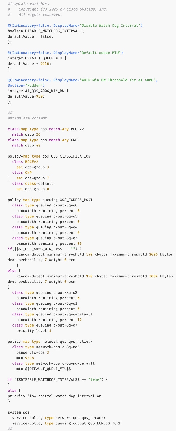
Step 9. Go to Manage > Fabrics. Select the backend fabric from the list and click the backend fabric name.
Step 10. Go to Actions and Edit Fabric Settings from the drop-down list. In the General tab, select the new QoS policy template from the drop-down list for AI QoS & Queueing Policy.
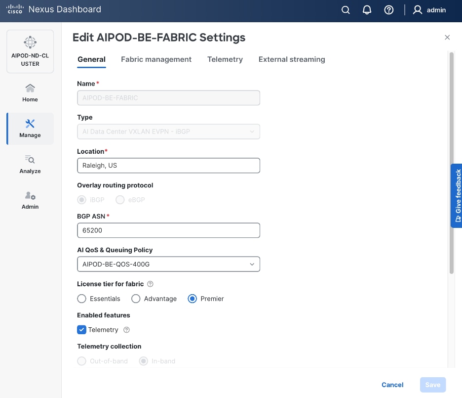
Step 11. To view the applied QoS configuration on the backend fabric switches, see the UCS Solutions GitHub Repo for the CVD. The complete configs for each switch in the fabric are provided in the GitHub repo (Nexus folder).
Enable GPU-to-GPU Networking between UCS GPU Nodes across Backend Fabric
Assumptions and Prerequisites
● Backend VXLAN EVPN fabric deployed
Setup Information
Table 22. Setup Information for GPU-to-GPU networking across BE Fabric
| Parameter Type |
Parameter Name | Value |
Parameter Type / Other Info |
| BE Network |
|
|
| Network Name |
BE-MLPerf_VNI_33590 |
|
| Layer 2 Only |
Enable checkbox |
|
| Network ID |
33590 |
|
| VLAN ID |
3590 |
|
| VLAN Name |
BE-MLPerf_VLAN_3590 |
|
| Interface Description |
BE-MLPerf_VLAN |
|
| Ports Connecting to UCS Servers |
Assumed to be same on all leaf switches |
|
| Interface List |
Ethernet 1/1-8 |
|
| Port type |
Access port (int_access_host) |
Default = trunk port (int_trunk_host) |
| Enable port type fast |
Enable checkbox |
|
Deployment Steps
To enable GPU-to-GPU network between UCS GPU nodes across the backend fabric, follow the procedures below using the setup information provided in Table 22.
Procedure 1. Configure ports going to UCS GPU nodes
Step 1. Filter the relevant interfaces going to UCS GPU nodes.
Step 2. Select the ports. Click the second of two Actions and select Configuration > Shutdown from the drop-down list to administratively shut the ports going to UCS GPU nodes.
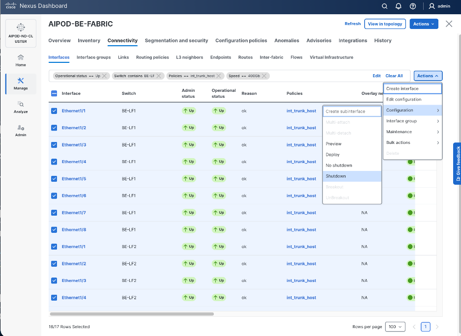
Step 3. Select the shutdown ports. Click the lower Actions button and select Edit Configuration to configure all ports going to UCS GPU nodes.
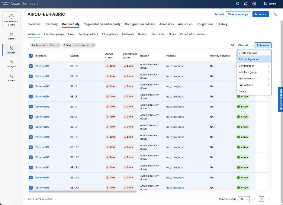
Step 4. Configure the first port from the list.
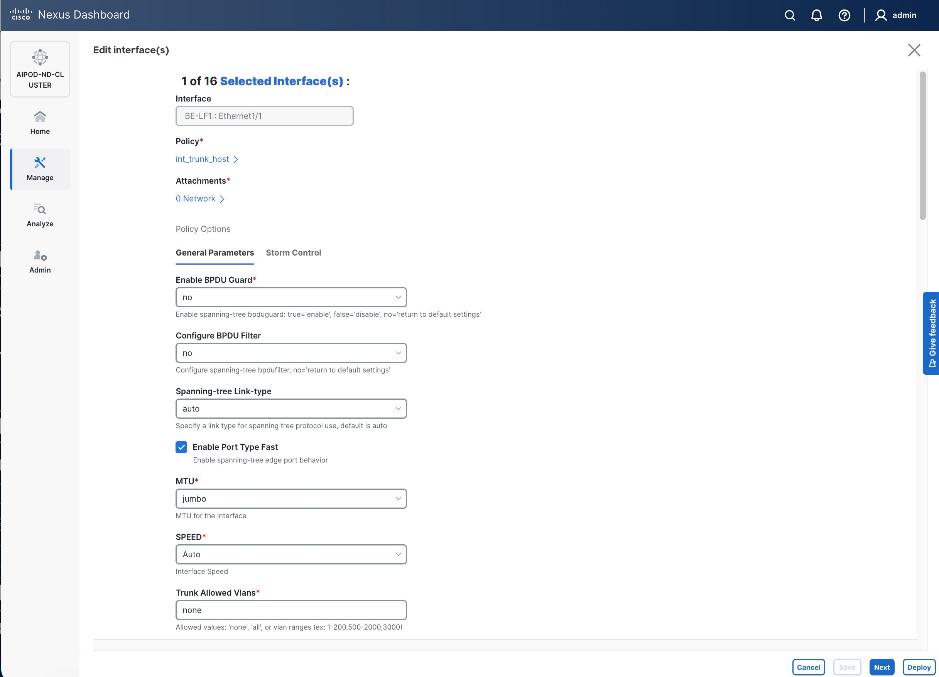
Step 5. Click int_trunk_host under Policy. In the Select Attached Policy Template pop-up window, select int_access_host from the drop-down list.
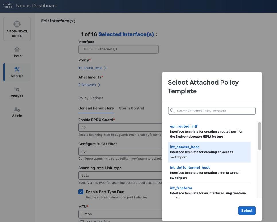
Step 6. Click Select.
Step 7. Make any other changes as needed. Click Save and click Next until all ports have been configured.
Step 8. Click Save.
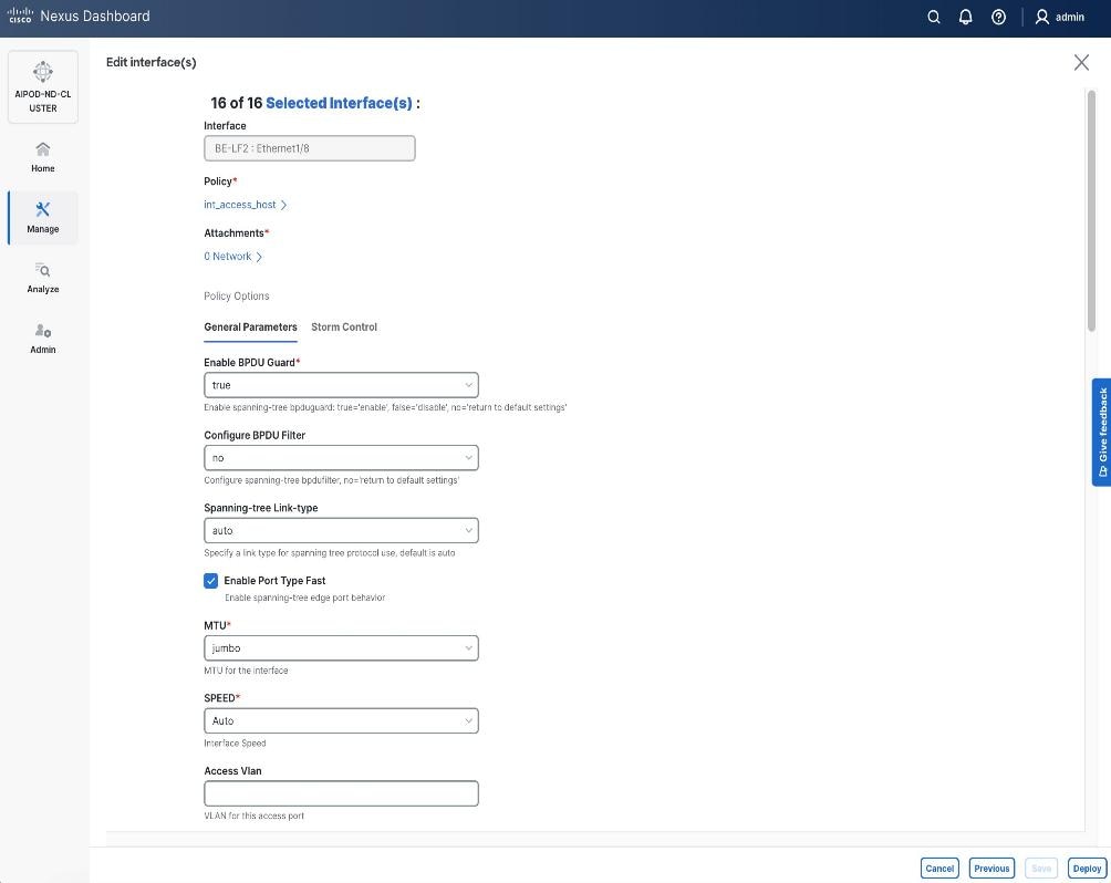
Step 9. Click Deploy.
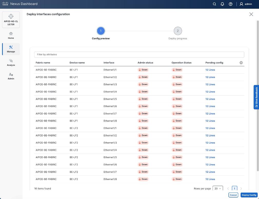
Step 10. Click the line count for each port in the Pending Config column to see the configuration being deployed.
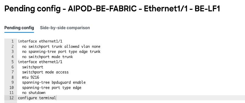
Step 11. Click Close.
Step 12. Click Deploy Config.
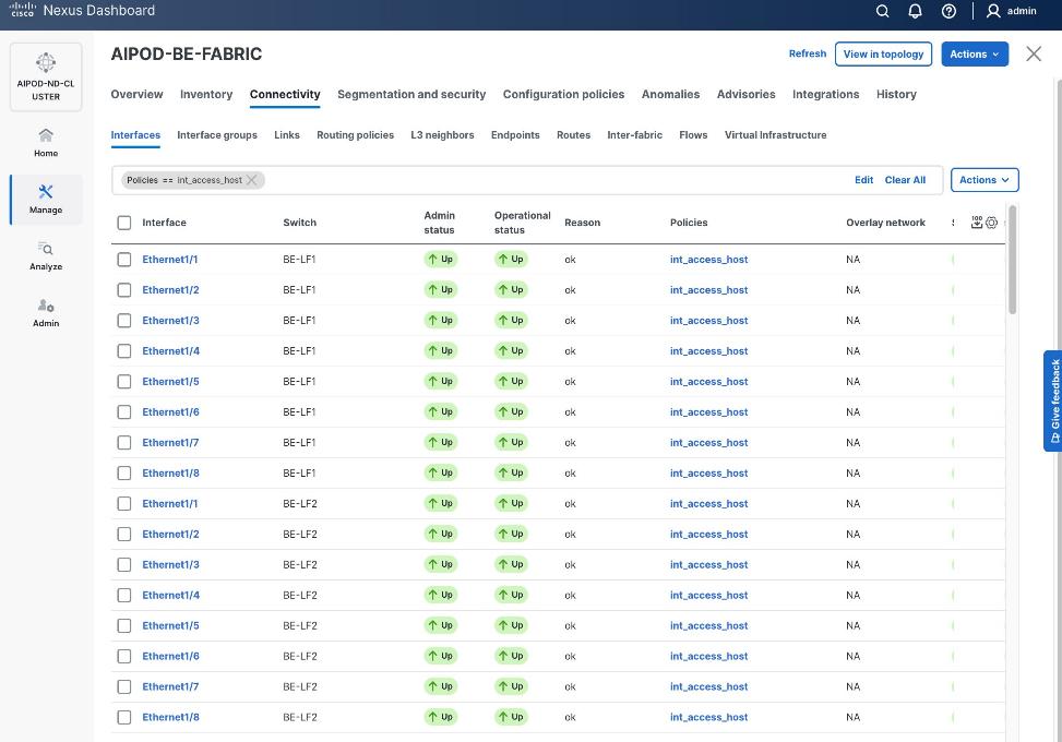
Procedure 2. Deploy L2 overlay network in the BE fabric for inter-node UCS connectivity
Step 1. From a browser, go to the Nexus Dashboard. Use the management IP of any node in the ND cluster. Log in using admin account.
Step 2. From the left navigation menu, go to Manage > Fabrics.
Step 3. Select the backend Fabric from the list and click the backend fabric name.
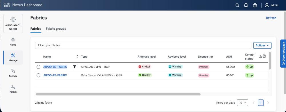
Step 4. Go to the Segmentation and Security > Networks tab. To deploy the backend network on UCS nodes, click the lower Actions button and select Create from the drop-down list.
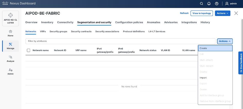
Step 5. In the Create Network window, specify the following:
● Network namename
● Enable checkbox for Layer 2Enable checkbox for Layer 2 onlyonly or VRF name if it is a Layer 3 network
● Network IDNetwork ID (or use default)
● VLAN IDVLAN ID (or use Propose VLAN for system to allocate).
● For a Layer 3 network, if VRF hasn't been created already, you have an option from this window to also create a VRF (click Create VRF).
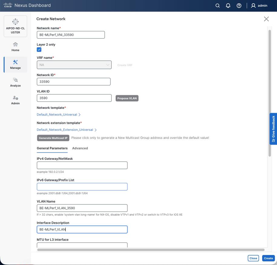
Step 6. Click Create to create the Layer 2 overlay network.
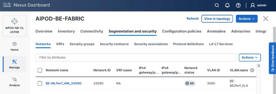
Step 7. Select the newly created network and deploy it on both leaf pairs. Click the lower Actions button and select Multi-attach from the list.
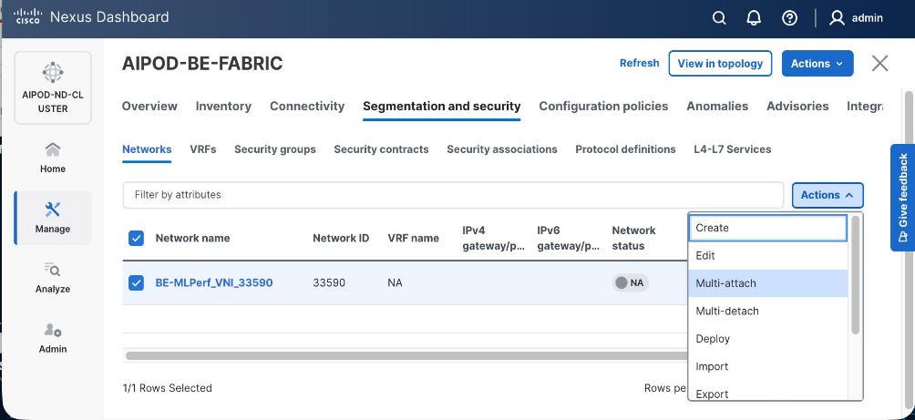
Step 8. Select both backend Leaf Switches.
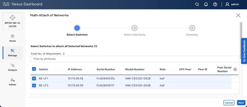
Step 9. Click Next. Select the row for the first switch and click Select Interfaces on the far right to select the interfaces going to the UCS C885A nodes on that switch.
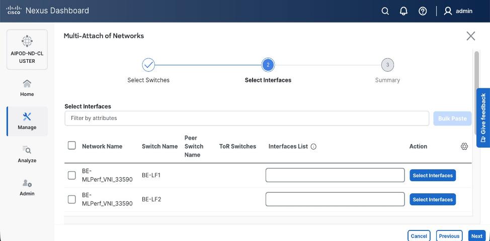
Step 10. Select all ports on the first switch that connect to UCS GPU nodes.
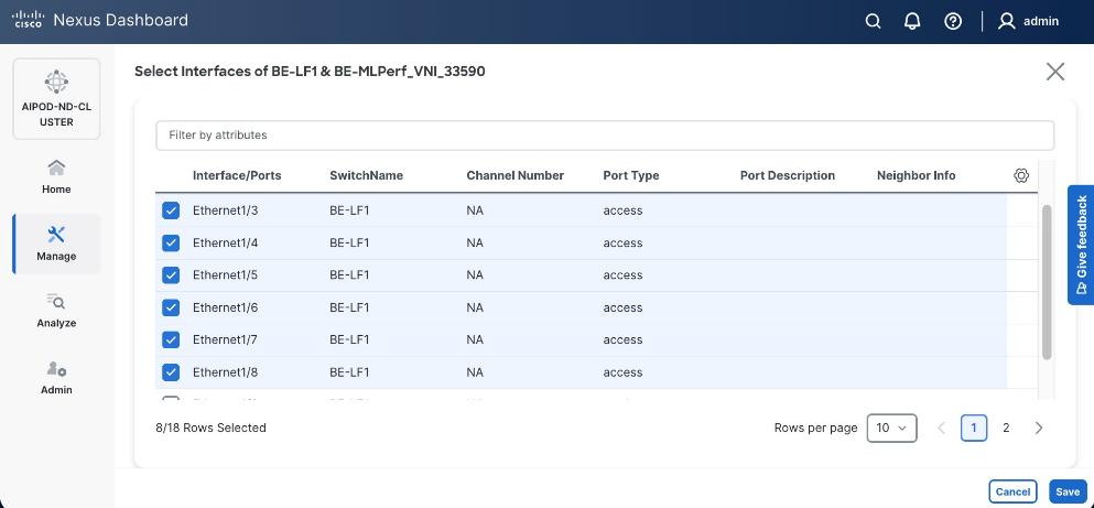
Step 11. Click Save.
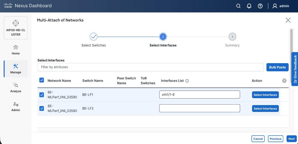
Step 12. Repeat steps 1 – 11 for the second leaf switch to select the ports going to the UCS GPU nodes on that switch. Repeat for any remaining leaf switches if you have more than two.
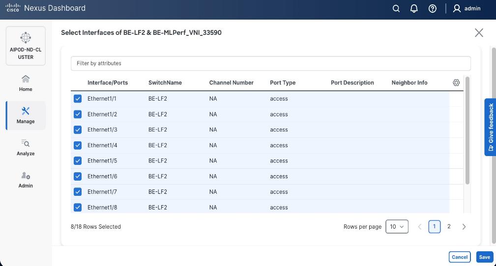
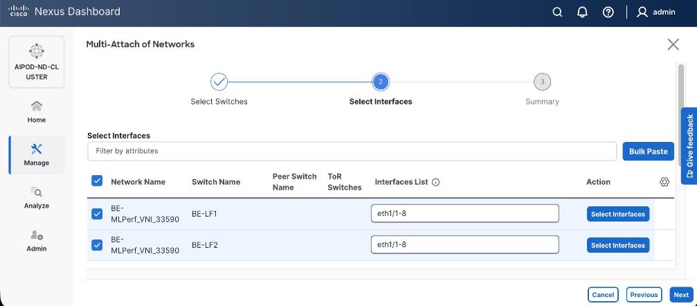
Step 13. Click Next.
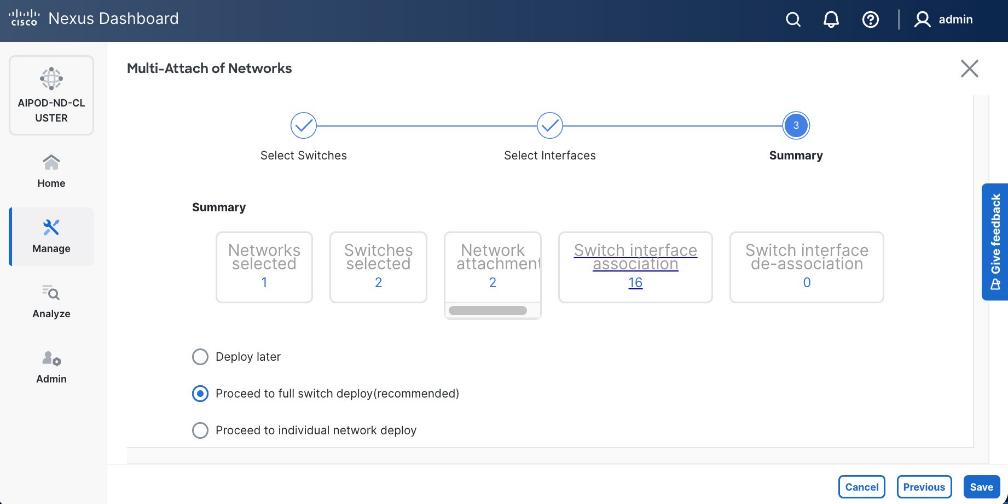
Step 14. Click Save.
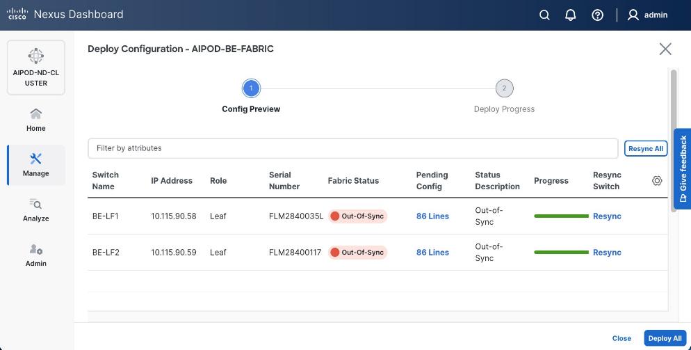
Note: Pending configuration being deployed on leaf switches is included at the end as a reference.
Step 15. Click Deploy All.
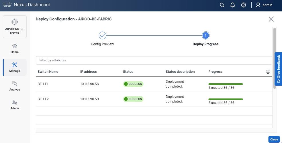
Step 16. Click Close.
Step 17. Click the network name and verify status is deployed.
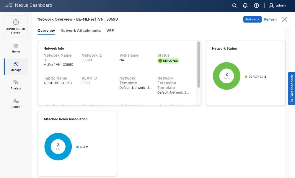

Step 18. Click X in the top right corner to close this window.
Step 19. Filter the newly deployed network 16 ports. Verify the status of all ports.
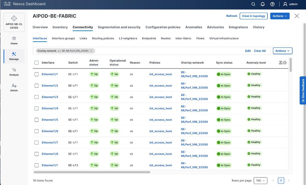
Step 20. Verify that ports on both switches are Up with an In-Sync status
Deploy NFS Storage on Everpure FlashBlade
This section outlines the procedures for provisioning NFS storage on Everpure FlashBlade. Portworx use this NFS storage as backend to provision persistent storage for the AI/ML workloads running on Cisco UCS C885A worker nodes in the AI POD training cluster.
The datastores are provisioned using management portal running on Everpure FlashBlade. The portal is accessible through an out-of-band management interface. The UCS GPU nodes will use the frontend fabric NIC to access storage on Everpure FlashBlade. When Red Hat OpenShift is deployed and Cisco UCS C885As nodes are added to this cluster as worker nodes (later in the document), NFS storage data access can be validated from each Cisco UCS C885A GPU node by performing controlled read and write operations using native NFS tooling. Successful NFS mount and file I/O confirm network connectivity, protocol access, and permissions. Once workloads are deployed, access can be additionally confirmed by observing active client connections and data activity from the FlashBlade management and data flow over the frontend interfaces.
Deploying NFS storage on Everpure FlashBlade involves the following tasks:
● Configure subnet for NFS storage access
● Create NFS endpoint for NFS storage access
● Export NFS filesystem and specify access policies
Assumptions and Prerequisites
● Initial setup and configuration of Everpure FlashBlade is complete and ready for provisioning datastores
● Network connectivity from storage leaf pairs in the frontend fabric to Everpure FlashBlade has been provisioned for NFS.
● LAG interface provisioned on Everpure FlashBlade
● Server provisioned on Everpure FlashBlade
Setup Information
Table 23. Setup Parameters for NFS Storage Setup on Everpure FlashBlade
| Parameter Type |
Parameter Name | Value |
Parameter Type |
| NFS Subnet |
|
|
| Subnet Name |
Pure-NFS-v3054 |
|
| Prefix |
192.168.54.0/24 |
|
| VLAN |
3054 |
|
| Gateway IP |
N/A |
L2; Not routed |
| MTU |
9000 |
|
| LAG |
uplink |
See prerequisite list above |
| NFS Network |
|
|
| Interface Name |
NFS-2_INT |
|
| Subnet |
Same as Subnet Name above |
|
| Address |
192.168.54.15 |
|
| Services |
data |
|
| Selected Server |
_array_server |
See prerequisite list above |
| Export NFS Filesystem |
|
|
| Server Name |
Same as “Selected Server’ above |
|
| File System Name |
<specify> |
|
| File System Type |
<specify> |
|
| Export Policy |
<specify> |
Enabled = True |
Deployment Steps
To deploy NFS datastores on Everpure FlashBlade, complete the procedures below using the setup information provided in this section.
Create Subnet for NFS Storage Access
Procedure 1. Subnet for NFS storage access
Step 1. From a browser, log into the management portal on Everpure FlashBlade.
Step 2. From the left navigation menu, in the network section, go to Settings > Subnets & Interfaces.
Step 3. In the Create Subnet window, specify the following:
◦ Name for Subnet used for NFS storage access
◦ Prefix – IP Subnet
◦ VLAN (if tagged)
◦ Gateway IP (if routed)
◦ MTU – should be same end-to-end
◦ LAG – interface that will carry the tagged VLAN for NFS storage access. Assumed to be setup prior to starting this configuration.
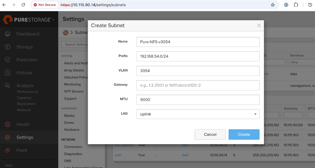
Step 4. Click Create.
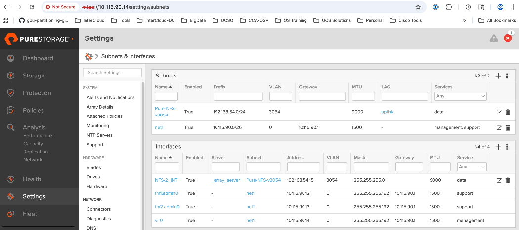
Create NFS Endpoint for NFS Storage Access
Procedure 1. NFS endpoint for NFS storage access
Step 1. From a browser, log into the management portal on Everpure FlashBlade.
Step 2. From the left navigation menu, in the network section, go to Settings > Subnets & Interfaces.
Step 3. In the Create Network Interface window, specify the following:
◦ Name for Interface used for NFS storage access
◦ Subnet – previously configured subnet for NFS storage access
◦ Address (IP address from the previously configured subnet)
◦ Services – data (for storage data as opposed to management or support)
◦ Selected Server – specify NFS server
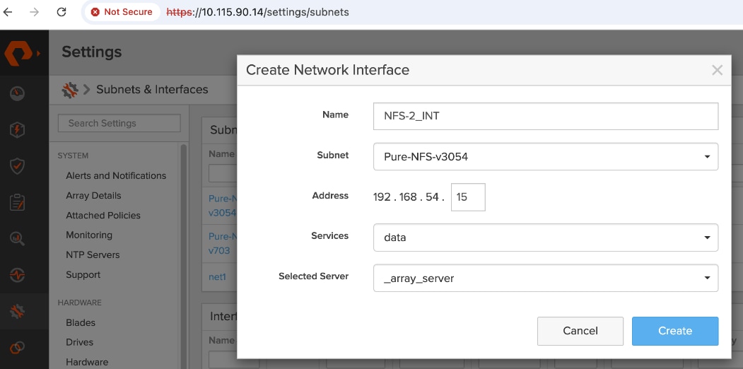
Step 4. Click Create.
Step 5. Verify the deployed configuration as shown below.
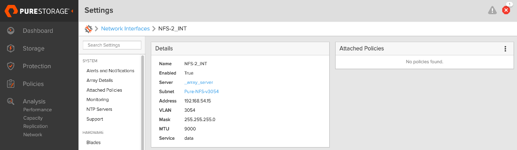
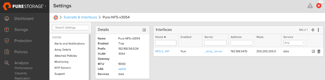
Export NFS Filesystem and Specify Access Policies
Procedure 1. NFS filesystem and access policies
Step 1. From a browser, log into the management portal on Everpure FlashBlade.
Step 2. From the left navigation menu, go to Storage > Servers.
Step 3. Click the server name specified in previous procedure.
Step 4. Edit the NFS server configuration to specify a file system to export. Specify the File System name, Type, export Policy and Enabled (True). Choose default policy or specify a policy that meets the needs of your environment.
Step 5. Verify the deployed configuration as shown below.
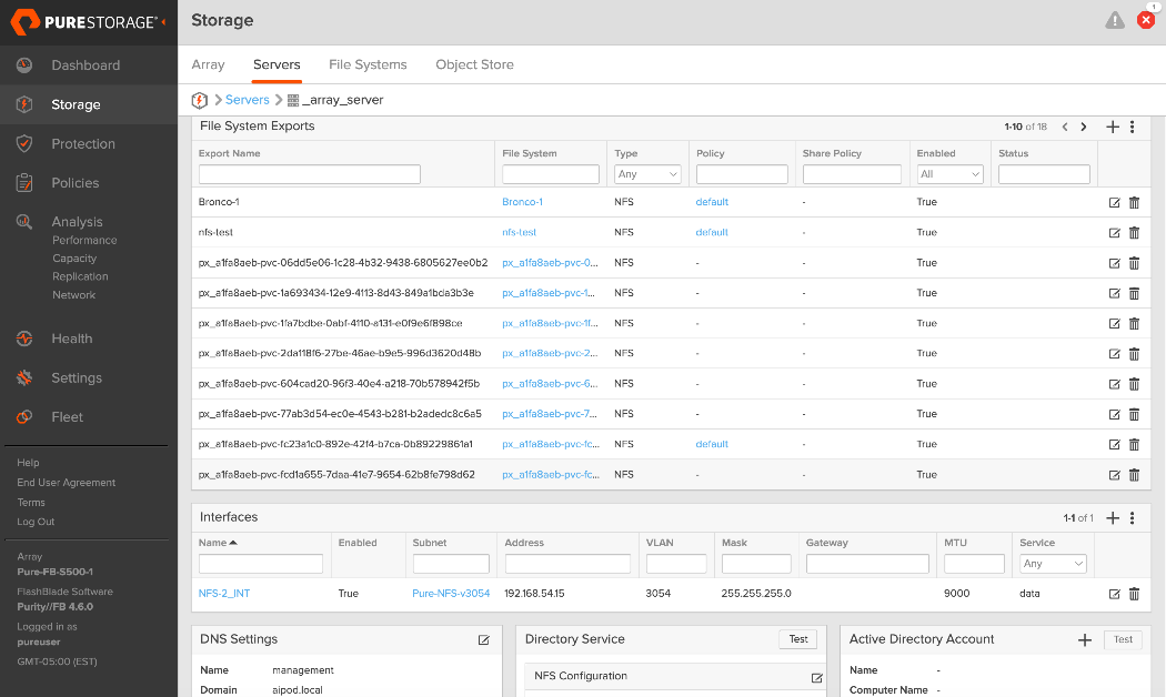
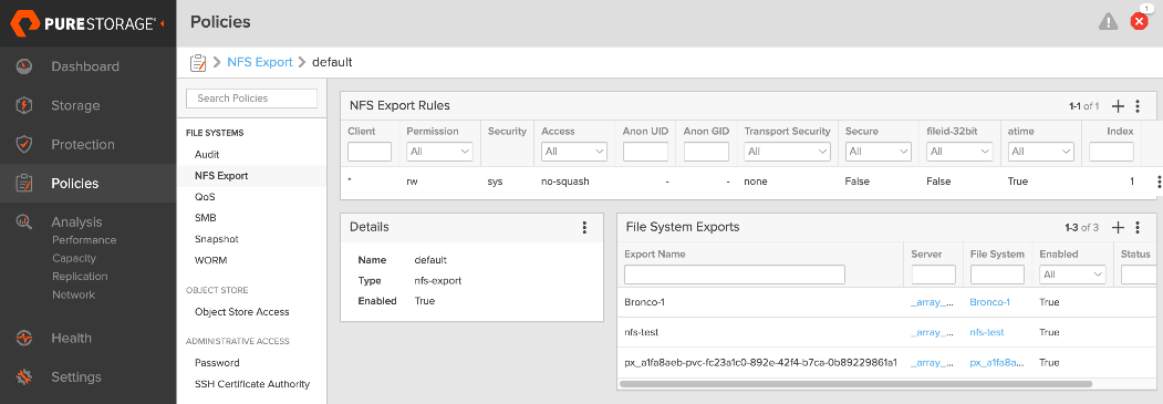
Deploy Object Store on Everpure FlashBlade
This section outlines the procedures for provisioning S3-compatible object store(s) on Everpure FlashBlade. This is needed in the different life-cycle stages of an AI/ML workload. For example, it can be used as a model repo or to store results from automated pipeline runs and related metadata.
The datastores are provisioned using the Everpure management portal running on the FlashBlade. The UCS GPU nodes will use the frontend fabric NIC to access storage on Everpure FlashBlade. When Red Hat OpenShift is deployed with Cisco UCS C885A as worker nodes in the cluster (later in the document), object store access can be validated from each Cisco UCS C885A GPU node by performing controlled read and write operations using native object store tooling. Successful object PUT/GET operations, confirm network connectivity, protocol access, and permissions. Once workloads are deployed, access can be additionally confirmed by observing active client connections and data activity from the FlashBlade management and data flow over the frontend interfaces.
Note: In an OpenShift deployment, access to the object store(s) is through the OpenShift cluster IP. In this design, traffic routed from the cluster IP subnet to the object store subnet in the same VRF.
Deploying S3-compatible object store on Everpure FlashBlade involves the following tasks:
● Configure subnetsubnet for object store access
● Create an AccountAccount and specify quotaquota for the object store account
● Create a useruser, specify access policies, and generate Access KeyAccess Key to access the S3 bucket
● Create S3 bucketS3 bucket(s) for use
Assumptions and Prerequisites
● Initial setup and configuration of Everpure FlashBlade is complete, and ready for provisioning data stores.
● Network connectivity from storage leaf pairs in the frontend fabric to Everpure FlashBlade has been provisioned for object store.
Setup Information
Table 24. Setup Parameters for Object Store on Everpure FlashBlade
| Parameter Type |
Parameter Name | Value |
Parameter Type |
| Object Store Subnet |
|
|
| Subnet Name |
S3-OBJ_NNET |
|
| Prefix |
10.115.90.208/29 |
|
| VLAN |
570 |
|
| Gateway IP |
10.115.90.214 |
L2; Not routed |
| MTU |
9000 |
|
| LAG |
uplink |
See prerequisite list above |
| Object Store Network |
|
|
| Interface Name |
S3-OBJ_INT |
|
| Subnet |
Same as Subnet Name above |
|
| Address |
10.115.90.210 |
|
| Services |
data |
|
| Selected Server |
_array_server |
See prerequisite list above |
| S3 Account and User |
|
|
| Account Name |
aipod-s3-account |
|
| Username |
rhoai-admin |
|
| S3 Bicket |
|
|
| Bucket Name |
<specify> |
|
| Quota |
<specify> |
|
Deployment Steps
To deploy S3-compatible object store on Everpure FlashBlade, complete the procedures below using the setup information provided in this section.
Create Subnet for Object Store Access
Procedure 1. Subnet for object store access
Step 1. From a browser, log into the management portal on Everpure FlashBlade.
Step 2. From the left navigation menu, in the network section, go to Settings > Subnets & Interfaces.
Step 3. In the Create Subnet window, specify the following:
◦ Name for Subnet used for Object Store access
◦ Prefix – IP Subnet
◦ VLAN (if tagged)
◦ Gateway IP
◦ MTU – should be same end-to-end
◦ LAG – previously configured interface that will carry the tagged VLAN for object store access
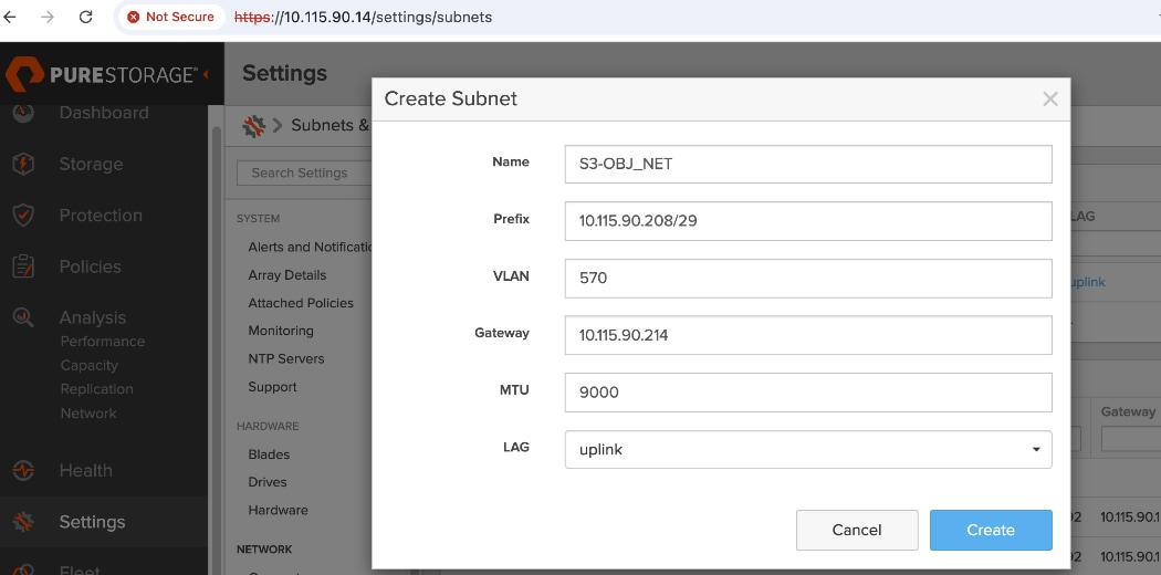
Create Network Interface for Object Store Data Access
Procedure 1. Network interface for object store data access
Step 1. From a browser, log into the management portal on Everpure FlashBlade.
Step 2. From the left navigation menu, in the network section, go to Settings > Subnets & Interfaces.
Step 3. In the Create Network Interface window, specify the following:
◦ Name for Interface used for NFS storage access
◦ Subnet – previously configured subnet for NFS storage access
◦ Address (IP address from the previously configured subnet)
◦ Services – data (for storage data as opposed to management or support)
◦ Selected Server – specify server
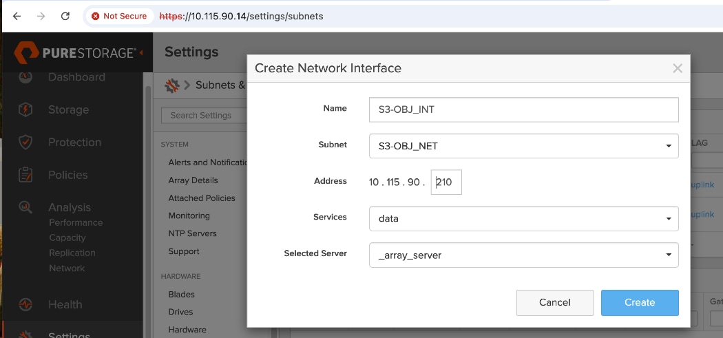
Step 4. Click Create.
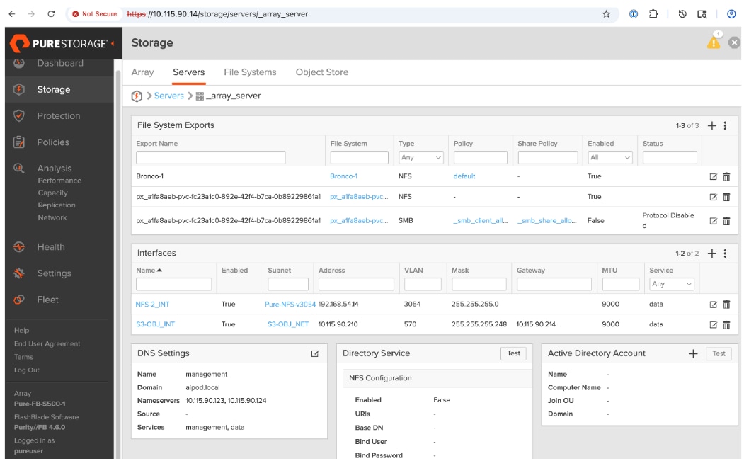
Create Account and Provision User
Procedure 1. Account and user
Step 1. From a browser, log into the management portal on Everpure FlashBlade.
Step 2. From the left navigation menu, go to Storage > Object Store.
Step 3. In the Accounts section, click '+' to create an account and specify quotas.
Step 4. Click the created account. In the Users section, click '+' to add a user.
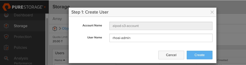
Step 5. In Step 1: Create User window, specify username. Click Create.
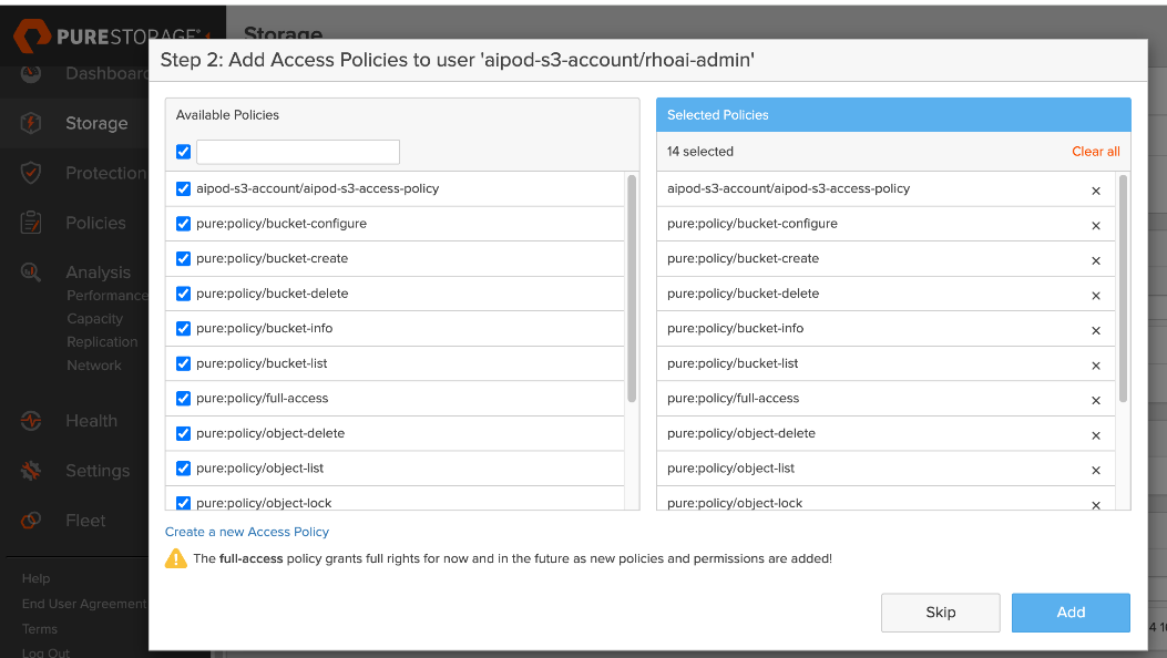
Step 6. In Step 2: Add Access Policies window, choose the relevant access policies for the newly created user. Click Add.
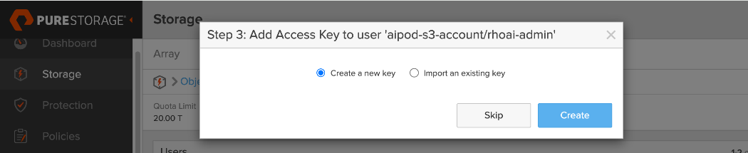
Step 7. In Step 3: Add Access Key to User window, choose the radio button for Create a new key. Click Create. This action generates the Access Key ID and Secret Access Key for the user.
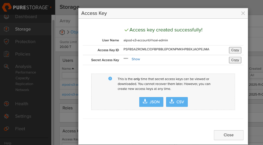
Step 8. In the Access Key window, copy and save all the information in a secure place. You will need this information to access the S3 bucket when it is created.
Deploy S3 Bucket on Everpure FlashBlade
Procedure 1. S3 bucket on Everpure FlashBlade
Step 1. From the left navigation menu, go to Storage > Object Store.
Step 2. In the Buckets section, click '+' to create a new S3 bucket. Specify a Bucket Name and Quota Limit. Click Create.
Step 3. The S3 bucket is now ready for use. Repeat this procedure as needed to deploy additional buckets.
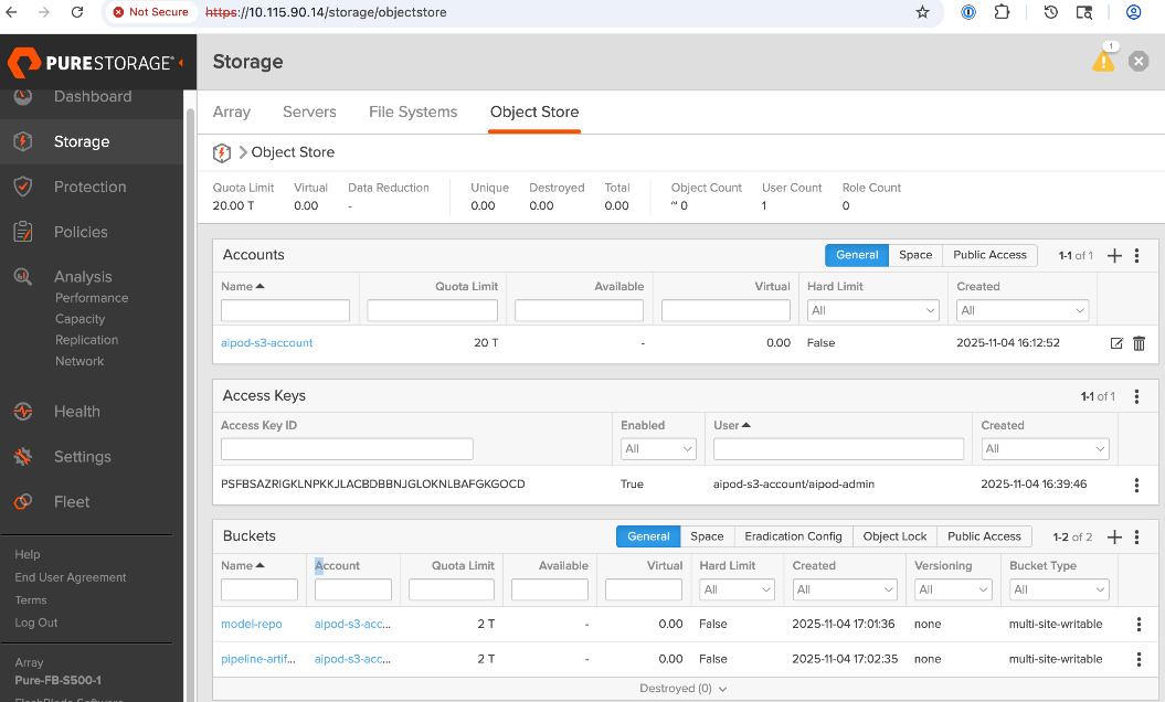
Deploy UCS Management Nodes from Cisco Intersight
This section serves as a placeholder to provision a Cisco UCS X-Direct system with 3 servers as OpenShift control nodes. This deployment is not covered in this document as this information can be found in several CVDs on Design Zone. A PDF of the relevant sections from a similar deployment will be made available in the AI POD GitHub repo (UCS section). These CVDs can be used to generate a server profile template in Cisco Intersight that captures the configuration of these servers. To provision the UCS control nodes in the cluster, the server profile template can be used to instantiate multiple server profiles to individually provision each server.
The UCS control nodes should be configured minimally with one network interface in the OpenShift Cluster management (same as IB-MGMT VLAN) network. Additional interfaces (for example, storage) can be added later using the Red Hat NMState operator in OpenShift. In this CVD, the control nodes are also worker nodes (OpenShift compact cluster) in order to host services and other virtual machines using OpenShift virtualization. The deployment of OpenShift virtualization and services VMs is outside the scope of this document.
It is important to note that Red Hat OpenShift Assisted Installer provides a key integration for Cisco Intersight that simplifies the installation of OpenShift on bare metal servers. As shown in Figure 17, the Assisted Installer workflow includes a link to add servers directly from Cisco Intersight.
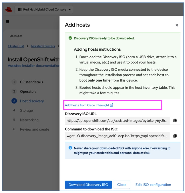
This integration allows the UCS servers managed by Cisco Intersight to be discovered within the Red Hat OpenShift Assisted Installer (Figure 18), enabling a seamless installation of either the discovery or full ISO.
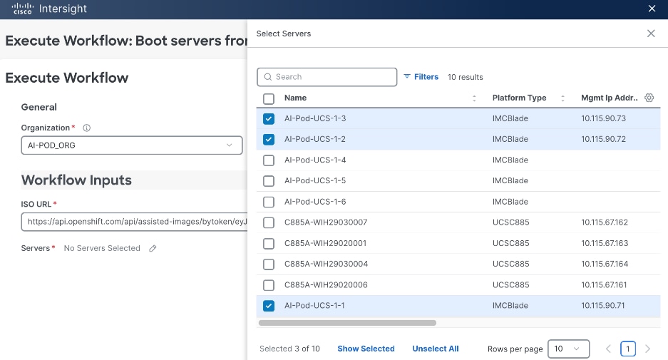
For more information on this feature, see: https://intersight.com/help/saas/orchestration/tutorial_workflow/workflow_OpenShift
Deploy Red Hat OpenShift on UCS Servers
This section details the procedures to bring up a Red Hat OpenShift cluster using Cisco UCS servers. The provisioned UCS servers (via Cisco Intersight, Redfish, or GUI) will serve as control and worker nodes in the cluster.
The cluster will first be brought up as a compact cluster where control nodes are also worker nodes. The three control nodes in this deployment will be Cisco UCS X-series M8 servers in a Cisco UCS X-Series Direct chassis.
The Cisco UCS C885A M8 GPU servers will then be added to this cluster as worker nodes.
The procedures in this section:
● Setup prerequisites for deploying the cluster such as setting up an installer workstation, DNS, DHCP, and so on
● Deploy OpenShift cluster using Assisted Installer workflow from Red Hat Hybrid Cloud Console (console.redhat.com)
● Post-deployment setup such as saving downloading oc tools, saving kubeconfig file, reserving resources for system components, NTP, and so on
Assumptions and Prerequisites
● Cisco Intersight Account and licenses to access and manage UCS servers in the OpenShift cluster
● Red Hat Account to access Red Hat Hybrid Cloud Console (console.redhat.com)
● DNS, DHCP server deployed and ready for provisioning IP and DNS info for the UCS nodes in the cluster
Setup Information
Table 25. Red Hat OpenShift Setup Information
| Parameter Type |
Parameter Name | Value |
Additional Information |
| OpenShift Installer machine |
10.115.90.65/26 |
|
| NTP |
1.ntp.esl.cisco.com 2.ntp.esl.cisco.com 3.ntp.esl.cisco.com |
Add at least two NTP sources for redundancy |
| DNS Server |
Primary: 10.115.90.123/26 Secondary: 10.115.90.124/26 |
Windows AD Server used in this CVD. Secondary is hosted on UCS Management nodes using OpenShift Virtualization |
| DHCP Server |
Primary: 10.115.90.123/26 Secondary: 10.115.90.124/26 |
Windows AD server used in this CVD. Secondary is hosted on UCS Management nodes using OpenShift Virtualization |
| Red Hat OpenShift Cluster Prerequisites: DNS Setup |
||
| Base Domain |
aipod.local |
|
| OpenShift Cluster Name |
ocp-c885 |
|
| Sub-Domain |
apps |
|
| IP subnet for OpenShift Cluster |
10.115.90.64/26 |
|
| Default Gateway IP |
10.115.90.126/26 |
|
| API VIP |
api.ocp-c885.aipod.local |
10.115.90.81/26 |
| Ingress VIP |
*.apps.ocp-c885.aipod.local |
10.115.90.82/26 |
| Red Hat OpenShift Cluster Prerequisites: DHCP Setup |
||
| OpenShift Control Nodes (UCS-X) |
10.115.90.[83-85]/26 |
vNIC: eno5 Compact Cluster so also worker nodes CIMC IPs: 10.115.90.[.71-73]/26 |
| OpenShift Worker Nodes (UCS-C885A) |
10.115.90.[86-89]/26 |
UCS GPU Nodes CIMC IPs: 10.115.67.[161-164]/26 |
| Red Hat OpenShift: Install Cluster |
||
| OpenShift Cluster Name |
ocp-c885 |
|
| Base Domain |
aipod.local |
|
Deployment Steps
To deploy Red Hat OpenShift on an AI cluster with Cisco UCS management and worker (GPU) servers, complete the procedures in this section using the setup information provided above.
Setup Prerequisites
To setup the prerequisites for installing a Red Hat OpenShift cluster, complete the procedures in this section using the setup information provided in this section.
Procedure 1. Deploy and setup an installer workstation to manage the OpenShift cluster
Step 1. Deploy a Linux (Rocky Linux, RHEL, others) workstation to manage the OpenShift cluster using CLI.
Step 2. When the workstation is up and running, enable network connectivity to the IP subnet for the OpenShift cluster being deployed.
Step 3. From the OpenShift Installer machine, create a new directory (for example: ocp-c885) for storing all data related to the new cluster being deployed.
Step 4. To enable SSH access to OpenShift cluster, go to the newly created directory and run the following commands to generate a SSH key pair to enable SSH access to the OpenShift cluster nodes.
Note: This must be done prior to cluster deployment. You can use either rsa or edcsa algorithm.
cd <new directory for cluster>
ssh-keygen -t rsa -N '' -f <path>/<file_name>
eval "$(ssh-agent -s)"
ssh-add <path>/<file_name>
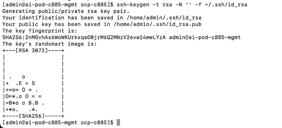
Step 5. Verify that the ssh-agent process is running and if not, start it as a background task as shown below:

Step 6. Add the SSH private key identity to the SSH agent for your local user.

Note: The SSH keys generated above will be provided to the Red Hat OpenShift Assisted Installer later in the installation process. The installer adds these keys to the ignition files used in the initial configuration of OpenShift nodes. You will then be able to SSH as user core without a password from this installer workstation once OpenShift is deployed.
Procedure 2. Add DNS records for OpenShift cluster API and Ingress IP address
Step 1. On the DNS server, create a domain (for example, ocp-c885) and sub-domain (apps) under the parent/base domain (for example, aipod.local).
Note: For this CVD, a Windows AD server is used for DNS.
The DNS configuration for this cluster is shown below:
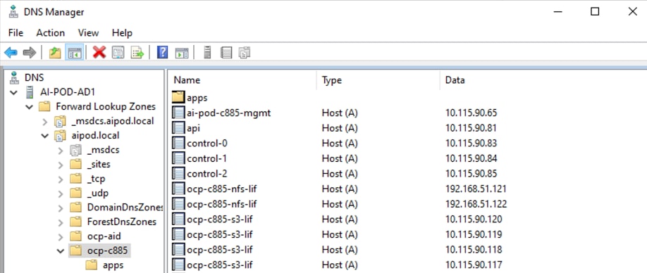
Procedure 3. Add DHCP Pools and configure the DHCP options for NTP, DNS, Gateway
Step 1. On the DHCP server, create DHCP scopes for OpenShift control and worker node subnets. For this CVD, the DHCP service is enabled on a Windows AD server. See setup information in this section for the IP addressing on the nodes.
Step 2. For each scope, the DHCP options for DNS, Router and NTP are configured as shown below:
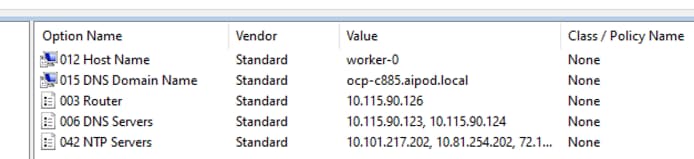
Install the Red Hat OpenShift Cluster
To deploy the Red Hat OpenShift Cluster, complete the procedures in this section using the setup information previously provided.
Procedure 1. Install OpenShift cluster using Assisted Installer from Red Hat Hybrid Cloud Console
Step 1. From a browser, go to console.redhat.com and log in with your Red Hat account.
Step 2. Go to Red Hat OpenShift > OpenShift tile.
Step 3. Click OpenShift.
Step 4. From the left navigation pane, select Cluster List.
Step 5. Click Create cluster.
Step 6. Go to the Datacenter tab.
Step 7. In the Assisted Installer section, click Create Cluster.
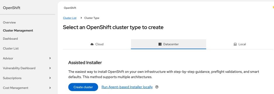
Step 8. In the Install OpenShift with the Assisted Installer workflow, for Cluster Details, specify the Cluster name and Base domain. Select the OpenShift version from the drop-down list. Leave everything else as is.
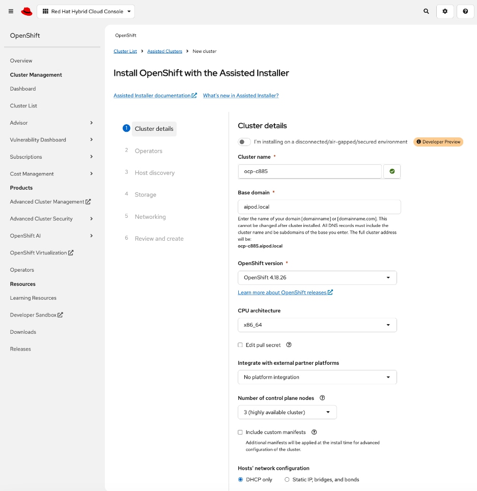
Step 9. Scroll down to the end of the page and click Next.
Step 10. For Operators, skip all options. Click Next.
Note: Multiple operators (network, GPU, storage, and so on) will be deployed later, after the cluster is deployed.
Step 11. For Host Discovery, click Add Hosts.
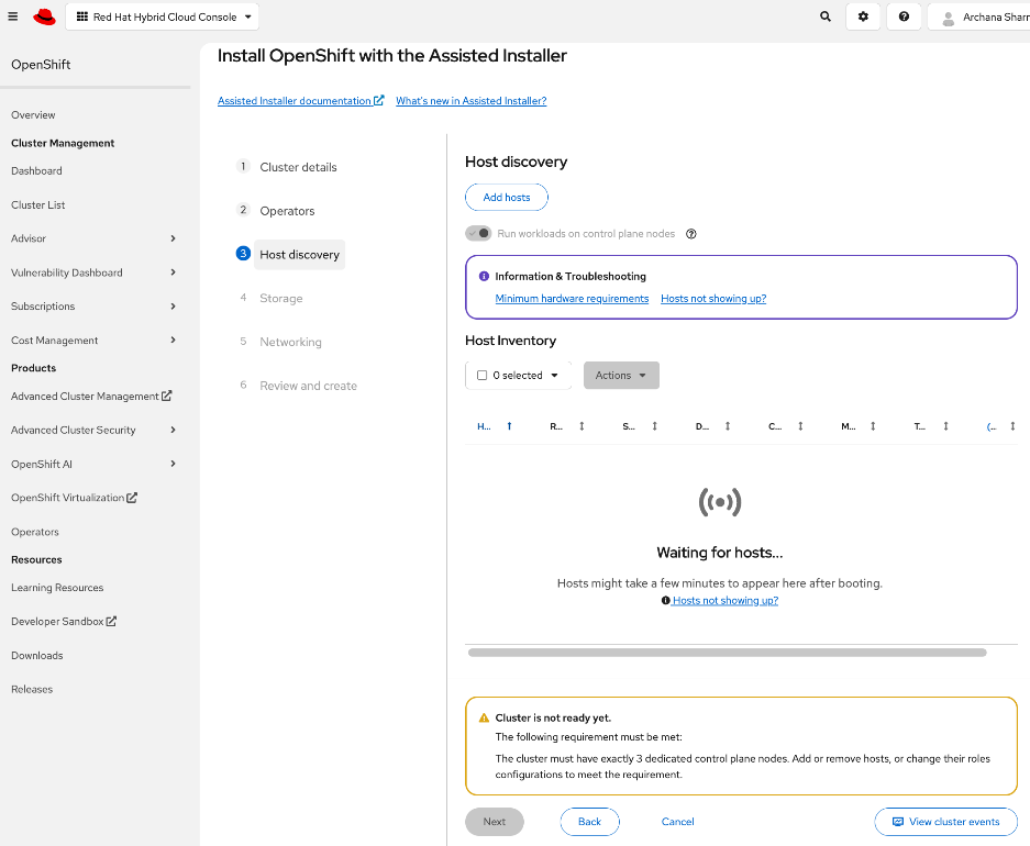
Step 12. In the Add Hosts pop-up window, for the Provisioning Type, choose Minimal image file from the drop-down list.
Step 13. For the SSH public key, upload the SSH keys previously generated on the Installer workstation. Keep everything else as is.
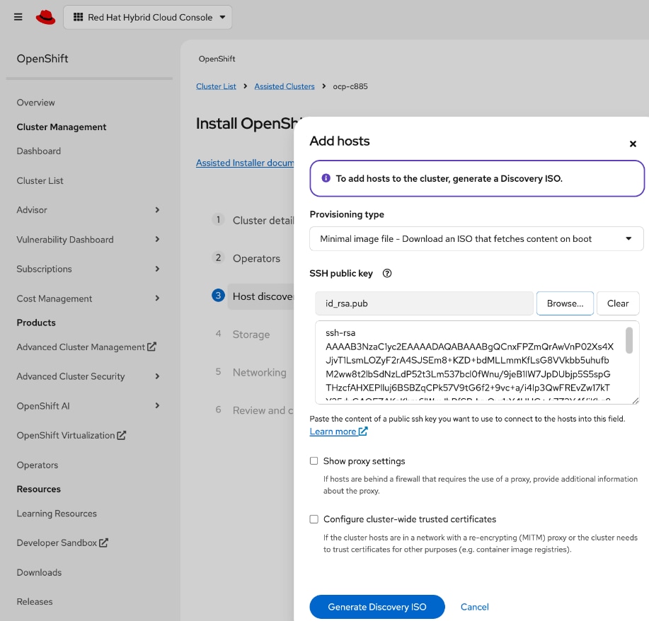
Step 14. Click Generate Discovery ISO.
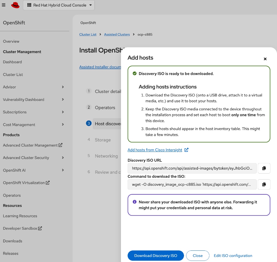
Step 15. In the Add hosts window, click the link to Add Hosts from Cisco Intersight to deploy the Discovery ISO on selected servers to start the installation process.
Step 16. You should now be directed to Cisco Intersight. Log in with your Cisco Intersight account that is used to manage the UCS servers in the OpenShift cluster.
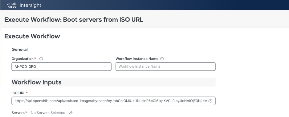
Step 17. In the Execute Workflow: Boot Servers from ISO URL window. For Organization, choose the Intersight organization that the UCS servers are part of. For Servers, click the pencil icon to the right of the No Servers Selected and select the UCS servers that will be part of the OpenShift cluster.

Step 18. Click X to cancel the Select Servers window.
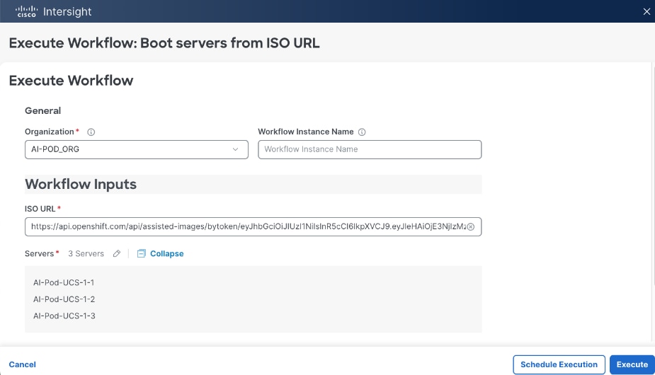
Step 19. The selected servers should now show up in the list. Click Execute to initiate a download of the Discovery ISOs to the selected servers that will serve as control (or worker nodes) in the OpenShift cluster.
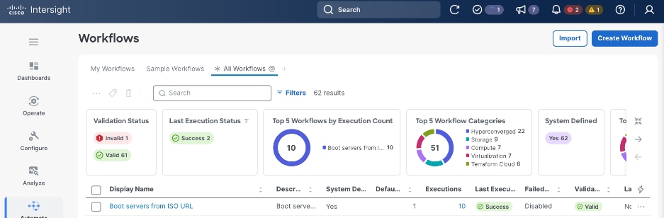
Step 20. In the Workflows view, click the Requests icon in the top menu bar to monitor the booting of the UCS servers.
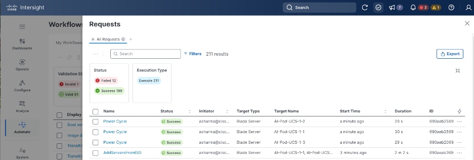
Step 21. You can also monitor the progress also by logging into the KVM console of each server. From the left navigation menu, select Operate > Servers and then select one of the servers from the list. Click the ellipses to the right of each server and select Launch vKVM from the drop-down list.
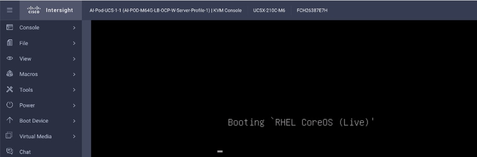
Step 22. If the discovery image is loading correctly, you should see the above message at some point during the boot process. This will take about 5 minutes to complete.
Step 23. Once the discovery image is loaded on all the nodes, return to the Hybrid Cloud Console and Assisted Installer. Click Close.
Step 24. After a several more minutes, you should start seeing the servers show up one by one as nodes in the Assisted Installer, in the Host Discovery > Host Inventory section. You can click View Cluster events to view relevant events.
Step 25. When all servers have booted from the Discovery ISO, they will appear in the Host Inventory list.
Step 26. For each server, under Role, specify whether it is a control, worker or compact node.
Step 27. Edit the hostname of each node by clicking on the default/current hostname.
Step 28. Expand each node and verify NTP is synced.
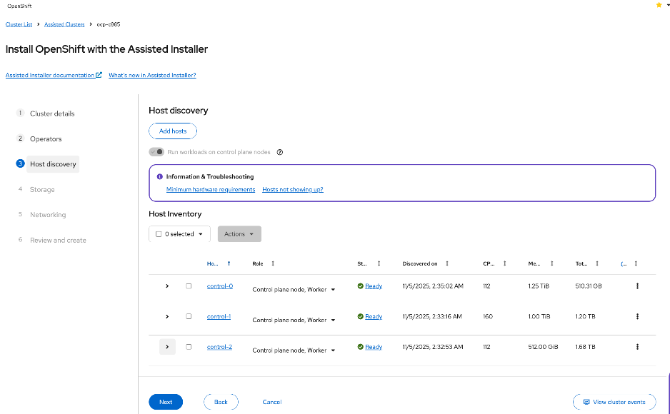
Step 29. Scroll down and click Next.
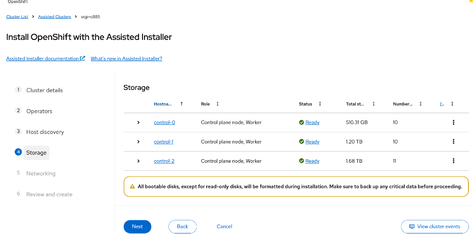
Step 30. Expand each node and confirm that the M.2 boot disk is set as the Installation disk. Click Next.
Step 31. For Networking, choose Cluster-Managed Networking. For Machine network, select the correct subnet from the list. Specify the API and Ingress IP in the corresponding fields. Leave everything else as is.
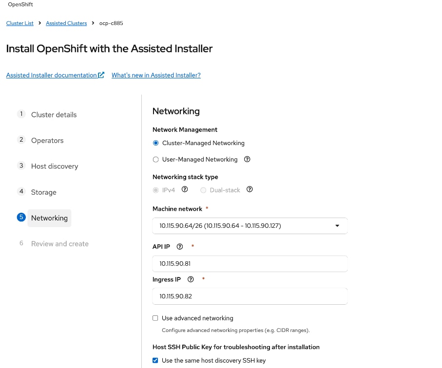
Step 32. Scroll down and verify that all nodes have a Ready status.
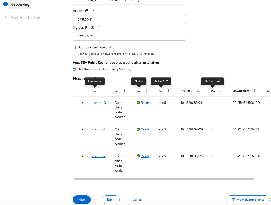
Step 33. When all nodes are in a Ready status, click Next.
Step 34. Review the information. Click Install cluster to begin the cluster installation.
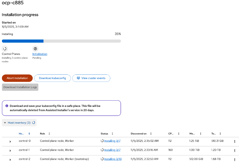
Step 35. On the Installation progress page, expand Host inventory. The installation will take 30-45 minutes.
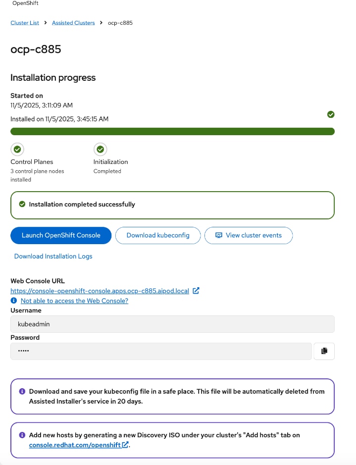
Step 36. Scroll down to view the Host inventory. If the installation completes successfully, all nodes should have a Installed status.
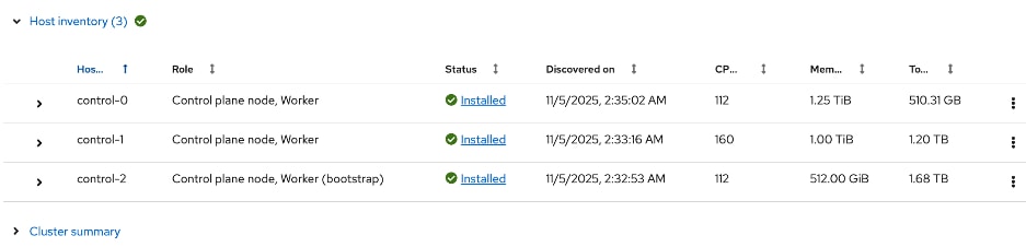
Step 37. You can expand each node and verify its configuration (for example, interface, IP addresses, and so on).
Step 38. Proceed to the post-installation setup in the next section.
Post-Install Setup
Once the OpenShift cluster is installed, complete the post-installation tasks and other verifications in this section using the setup information previoulsy provided.
Procedure 1. Download and save important installation files – kubeconfig and kubeadmin password
Step 1. In the cluster install window, click Download kubeconfig to download and save kubeconfig file in a safe location as instructed.

Step 2. Copy the file to the OpenShift Installer machine.

Step 3. From the installer workstation, run the following commands to create the following directories and move the file to specific location in the cluster directory.
[admin@ai-pod-c885-mgmt ~]$ cd ocp-c885
[admin@ai-pod-c885-mgmt ocp-c885]$ mkdir auth
[admin@ai-pod-c885-mgmt ocp-c885]$ cd auth/
[admin@ai-pod-c885-mgmt auth]$ mv ../kubeconfig .
[admin@ai-pod-c885-mgmt auth]$ ls
kubeconfig
[admin@ai-pod-c885-mgmt auth]$
[admin@ai-pod-c885-mgmt auth]$ mkdir ~/.kube
[admin@ai-pod-c885-mgmt auth]$ cp kubeconfig ~/.kube/config
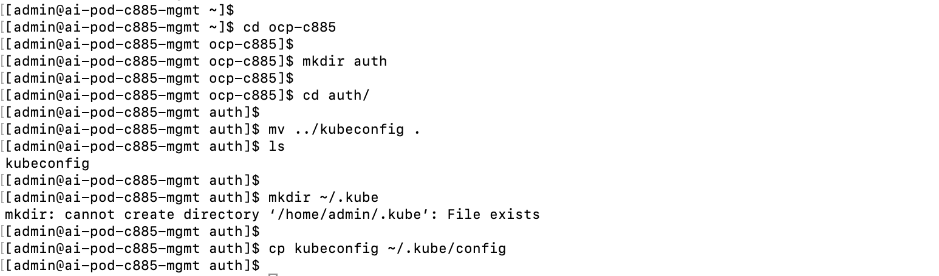
Step 4. Return to post-cluster installation page on Red Hat Hybrid Cloud Console. Click the icon next to kubeadmin password to copy the password.
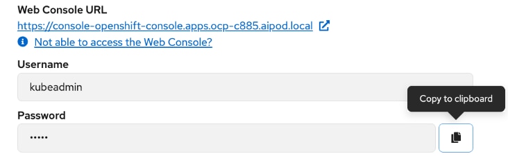
Step 5. On the installer machine, in a terminal window, run the following commands to copy and save the kubeadmin password in a location specified below:
echo <paste password> > ./kubeadmin-password
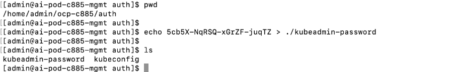
Procedure 2. Download oc tools
Step 1. Return to the post-cluster installation page on Red Hat Hybrid Cloud Console and click Launch OpenShift Console to login to the newly deployed OpenShift cluster.
Step 2. Pop-up window shows options for accessing the OpenShift cluster console without DNS issues. You may need to add a DNS entry for downloads-openshift-console.apps.ocp-c885.aipod.local as well.
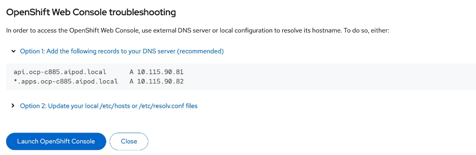
Step 3. Once you have DNS entries in place for the new cluster, click Launch OpenShift Console again. Log in using the kubeadmin and the kubeadmin password.
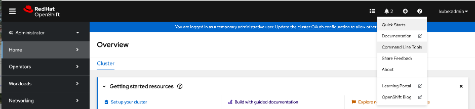
Step 4. From the top menu bar, click the ? icon and select Command Line Tools from the drop-down list.
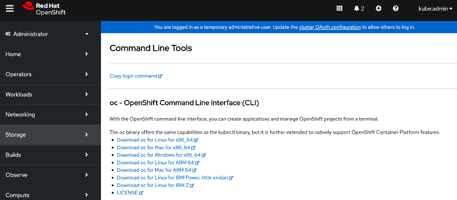
Step 5. Click Download oc for Linux for x86_64. Links to other tools are also available on this page.
Step 6. Copy the file to the OpenShift Installer machine.

Step 7. Move and save the file in a sub-directory in the cluster directory as shown below.
[admin@ai-pod-c885-mgmt ocp-c885]$ pwd
/home/admin/ocp-c885
[admin@ai-pod-c885-mgmt ocp-c885]$ mkdir client
[admin@ai-pod-c885-mgmt ocp-c885]$ cd client
[admin@ai-pod-c885-mgmt client]$ mv ../oc.tar .
[admin@ai-pod-c885-mgmt client]$ tar xvf oc.tar
oc
[admin@ai-pod-c885-mgmt client]$ ls
oc oc.tar
[admin@ai-pod-c885-mgmt client]$ sudo mv oc /usr/local/bin
[sudo] password for admin:
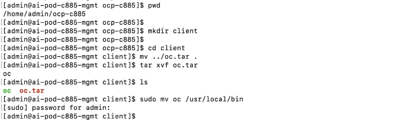
Step 8. To enable oc tab completion for bash, run the following:
[admin@ai-pod-c885-mgmt client]$ oc completion bash > oc_bash_completion
[admin@ai-pod-c885-mgmt client]$ sudo mv oc_bash_completion /etc/bash_completion.d/
Step 9. Verify the status of the nodes in the cluster. You can also confirm that SSH as core user (no password) to the nodes work.
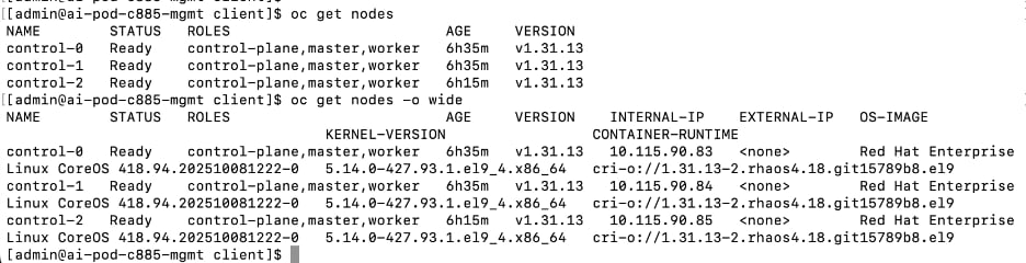
Procedure 3. Set up Power Management for Bare Metal Hosts
Step 1. From the OpenShift cluster console, go to Compute > Bare Metal Hosts.
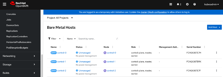
Step 2. For each Bare Metal Host, click the ellipses to the right of the host.
Step 3. Select Edit Bare Metal Host and enable the checkbox for Enable power management. Specify the BMC IP address, username and password that was previously provisioned in the Local User policy for the server from Cisco Intersight. Also verify that the boot MAC address is the correct one for the specified IP address.
Note: If you’re using a dedicated network for managing the hosts out-of-band, specify the mac address and IP for that interface for Power Management. For an IPMI connection to the server, use the BMC IP address. However, for Redfish to connect to the server, use this format for the BMC address: redfish:///redfish/v1/Systems/<serial_number_of_server> and check Disable Certificate Verification.
Step 4. Click Save.
Step 5. In Compute > Bare Metal Hosts, the status of each host should display as Externally Provisioned with the Management Address populated. Now you can manage the power on the OpenShift hosts from the OpenShift cluster console.
Step 6. Repeat steps 1 - 5 for the remaining bare metal hosts in the cluster.
Procedure 4. (Optional) Reserve resources for system components on control and worker nodes
Red Hat recommends reserving cpu and memory resources for system components (kubelet, kube-proxy, etc.) on the nodes. OpenShift can automatically determine the optimal system-reserved CPU and memory resources for the nodes and update the nodes with these values when they start. This requires creating a KubeletConfig Custom Resource (CR) and setting the autoSizingReserved: true parameter in this CR.
Step 1. For worker nodes, from the OpenShift cluster console, click the + icon in the top menu bar and select Import YAML from the drop-down list. Paste the following into the Import YAML window.
apiVersion: machineconfiguration.openshift.io/v1
kind: KubeletConfig
metadata:
name: dynamic-node
spec:
autoSizingReserved: true
machineConfigPoolSelector:
matchLabels:
pools.operator.machineconfiguration.openshift.io/worker: ""
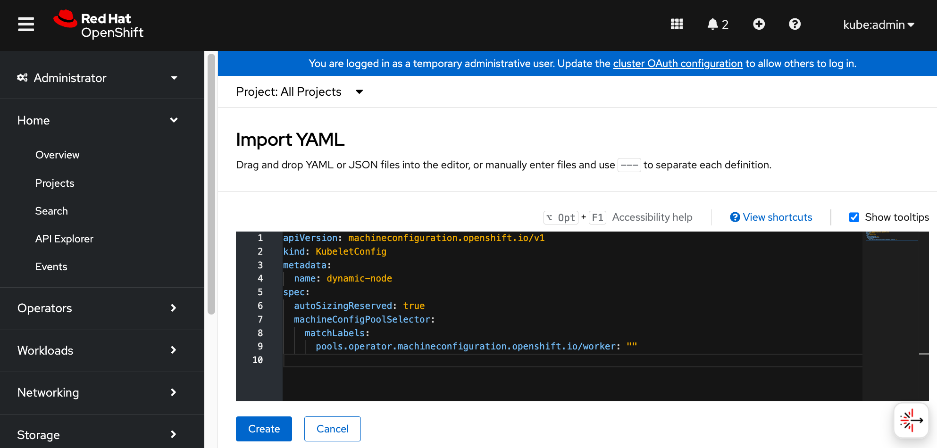
Step 2. Click Create.
Step 3. Repeat steps 1-3 for control nodes using the following configuration:
apiVersion: machineconfiguration.openshift.io/v1
kind: KubeletConfig
metadata:
name: dynamic-node-control-plane
spec:
autoSizingReserved: true
machineConfigPoolSelector:
matchLabels:
pools.operator.machineconfiguration.openshift.io/master: ""
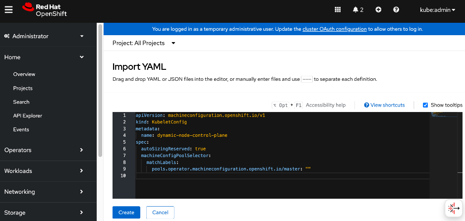
Step 4. Click Create.
Procedure 5. Setup NTP on control and worker nodes
Step 1. Log into the OpenShift Installer machine and create a new sub-directory for storing machine configs in the previously created cluster directory as shown below. Also download butane for creating the configuration files.
mkdir machine-configs
cd machine-configs
curl https://mirror.openshift.com/pub/openshift-v4/clients/butane/latest/butane --output butane
chmod +x butane
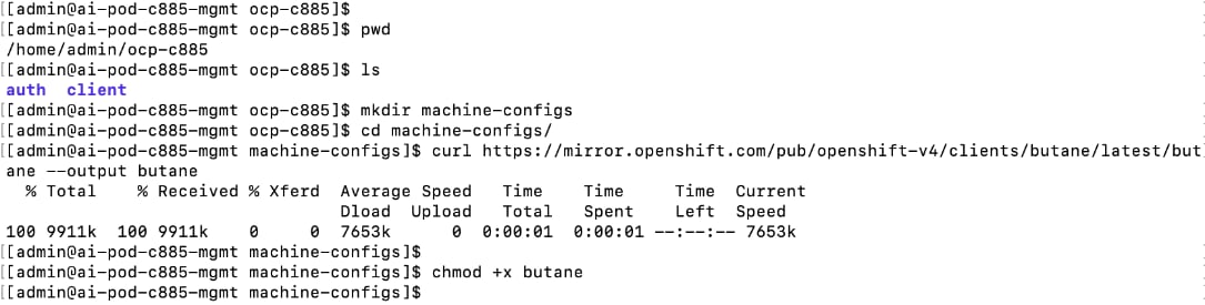
Step 2. Create the following files for control and worker nodes with the correct NTP IPs. Place the files in the machine-configs sub-directory.
File Name: 99-control-plane-chrony-conf-override.bu
variant: openshift
version: 4.18.0
metadata:
name: 99-control-plane-chrony-conf-override
labels:
machineconfiguration.openshift.io/role: master
storage:
files:
- path: /etc/chrony.conf
mode: 0644
overwrite: true
contents:
inline: |
driftfile /var/lib/chrony/drift
makestep 1.0 3
rtcsync
logdir /var/log/chrony
server 1.ntp.esl.cisco.com iburst
server 2.ntp.esl.cisco.com iburst
server 3.ntp.esl.cisco.com iburst
File: 99-worker-chrony-conf-override.bu
variant: openshift
version: 4.18.0
metadata:
name: 99-worker-chrony-conf-override
labels:
machineconfiguration.openshift.io/role: worker
storage:
files:
- path: /etc/chrony.conf
mode: 0644
overwrite: true
contents:
inline: |
driftfile /var/lib/chrony/drift
makestep 1.0 3
rtcsync
logdir /var/log/chrony
server 1.ntp.esl.cisco.com iburst
server 2.ntp.esl.cisco.com iburst
server 3.ntp.esl.cisco.com iburst
Step 3. Create the .yaml files from the butane files with butane:
./butane 99-control-plane-chrony-conf-override.bu -o ./99-control-plane-chrony-conf-override.yaml
./butane 99-worker-chrony-conf-override.bu -o ./99-worker-chrony-conf-override.yaml
Step 4. Apply the configuration to the OpenShift cluster:
oc create -f 99-control-plane-chrony-conf-override.yaml
oc create -f 99-worker-chrony-conf-override.yaml
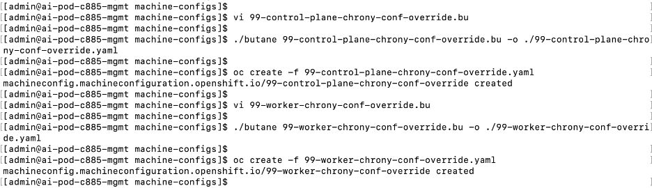
Step 5. Over the next 20-30 minutes each of the nodes will go through the Not Ready state and reboot. You can monitor this by going to Compute > MachineConfigPools in the OpenShift Console. Wait until both pools have an Update status of Up to date.
Step 6. Go to Compute > Nodes and verify that all nodes are operational and scheduling is enabled.
Procedure 6. Set up a second admin user
The default administrative user in a new OpenShift cluster is kube:admin. To setup an additional administrator, complete the following steps. You will also need this to be an administrator in OpenShift AI.
Note: The default OpenShift administrator (kube:admin) does not have Administrator privileges in OpenShift AI. You will not have a Settings menu in OpenShift AI for if you use this to login.
Step 1. SSH into the OpenShift Installer machine.
Step 2. Go to the cluster directory.
Step 3. Run the following command to create an user with administrator privileges:
Note: You can specify any username; admin is used in the example below.
htpasswd -c -B -b ./admin.htpasswd admin <specify_password>
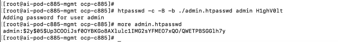
Step 4. Copy the contents of the admin.htpasswd.
Step 5. From a browser, log into the OpenShift Cluster Console.
Step 6. You should see a blue message bar at the top indicating that you’re logged in as a temporary administrative user. Click the link to Update the cluster OAuth configuration.
Step 7. In the Cluster OAuth configuration window, for IDP, choose HTPasswd from the drop-down list.
Step 8. In the Add Identify Provider:HTPasswd window, paste the contents of the admin.htpasswd file as shown below:
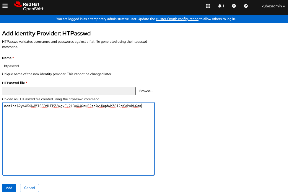
Step 9. Click Add.
Step 10. Logout and log back into OpenShift cluster console using kubeadmin account.
Step 11. Go to User Management > Users.
Step 12. Choose the user that was previously created using htpasswd. Click the username.
Step 13. In the User > User Details window, go to RoleBindings tab.
Step 14. Click Create binding.
Step 15. In the Create Rolebinding window, click Cluster-wide role binding (ClusterRoleBinding).
Step 16. Specify a name, such as oai-admin.
Step 17. For Role Name, choose cluster-admin from the drop-down list.
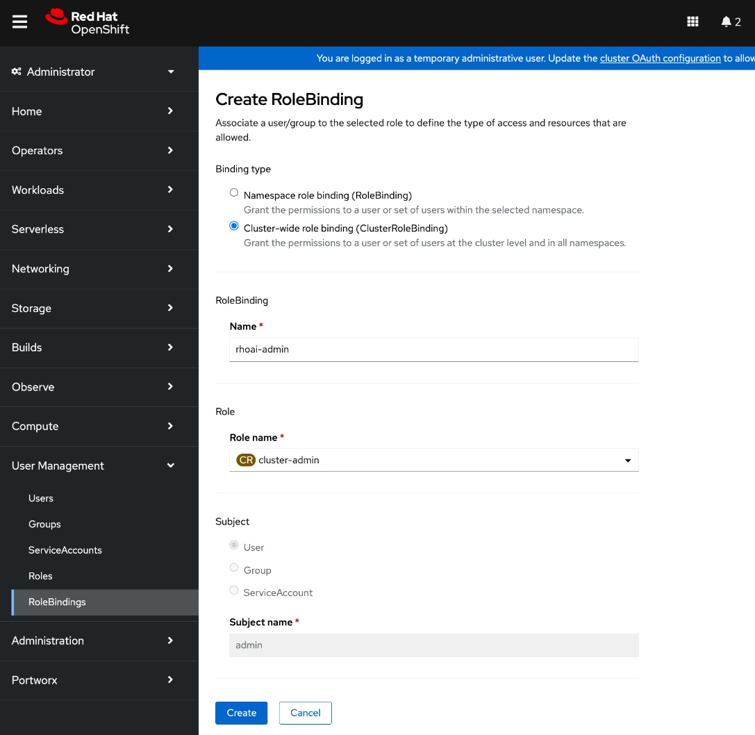
Step 18. Click Create.
Step 19. Logout and then log back into the Red Hat OpenShift cluster console. If you were previously logged in, you may need to open a browser window in Incognito mode to log in using the new account.
Step 20. Click htpasswd to login using the new admin user.
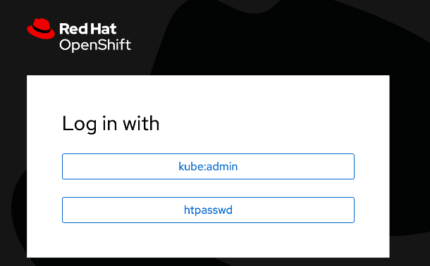
Initial Setup of Cisco UCS C885A GPU Servers
This section details the procedures for the initial setup of Cisco UCS C885A GPU servers. Cisco Intersight is currently limited to monitoring, so the setup is primarily done through Cisco BMC. The following procedures will address some of the prerequisites for adding the Cisco UCS C885A nodes as worker nodes to the OpenShift cluster.
The procedures in this section will:
● Configure NTP, DNS and other basic setup on UCS via Cisco BMC. See Cisco UCS C885A M8 Server Installation and Service GuideCisco UCS C885A M8 Server Installation and Service Guide for more info on the initial setup.
● Setup Intersight Management – Claim and add UCS C885A nodes in Cisco Intersight. You will need an Intersight account and licenses. For more info, see: Managing UCS C885 M8 serversManaging UCS C885 M8 servers.
● Collect MAC addresses of the frontend NIC from all UCS C885A Nodes. The first port will be provisioned as the cluster IP network in OpenShift. You can collect this from Intersight or via Cisco BMC. You can also collect NIC ID (slot) and MAC addresses for all NICs in the system. The NIC ID will be used later to determine the interface name.
● Create DHCP reservations for the mac addresses previously collected.
● Create DNS records for the reserved DHCP IP addresses.
● Create machine configuration files on installer VM. Cisco UCS C885A will require a Bare Metal Host (BMH) config. file using the above frontend NIC MAC address. You can also configure this later.
● Verify Redfish access to the UCS-C885A.
● Setup/Verify that the BlueField-3 NICs are in NIC mode (vs. DPU mode).
● Setup/Verify that the NVIDIA CX-7 cards are in Ethernet mode (vs. InfiniBand/IB).
● Upgrade to latest firmware for all components on the Cisco UCS C885A. Use Cisco UCS Hardware Compatibility (HCL) tool and Intersight HCL check to confirm the latest version is deployed on the node.
Assumptions and Prerequisites
● Out-of-band access to the BMC on the Cisco UCS C885A servers is setup. See Cisco UCS C885A M8 Server Installation and Service GuideCisco UCS C885A M8 Server Installation and Service Guide.
● Cisco Intersight Account and licenses to manage the UCS C885A servers in the OpenShift cluster.
● Red Hat Account to access Red Hat Hybrid Cloud Console (console.redhat.com).
● OpenShift Installer Machine has been deployed and setup. Installer machine will be used for CLI and SSH access to OpenShift cluster. You will also use this machine to create, store and deploy machine configs to the cluster at various stages.
● Red Hat OpenShift cluster has been deployed – Cisco UCS C885A nodes will be added to this cluster
● Set up backup SSH access to Cisco UCS C885A nodes using the Intel OCP NIC. This can be a jump-server with direct access (same subnet) to the node via Intel OCP NIC. No routing can be enabled on this NIC since the OpenShift cluster can only have one default gateway which is through the frontend NIC. Intel OCP is intended as a backdoor access in the event of driver or other issues that impact the frontend NIC.
Setup Information
Table 26. Cisco UCS C885A: CIMC IP Access Details
| UCS Node |
CIMC/KVM IP Address |
Access Info |
Default Access Info |
| UCS C885A-1 |
10.115.67.161 |
< new: username/password > |
root/password |
| UCS C885A-2 |
10.115.67.162 |
< new: username/password > |
root/password |
| UCS C885A-3 |
10.115.67.163 |
< new: username/password > |
root/password |
| UCS C885A-4 |
10.115.67.164 |
< new: username/password > |
root/password |
| Parameter Type |
Parameter Name | Value |
Additional Information |
| OpenShift Installer machine |
10.115.90.65/26 |
|
| NTP |
1.ntp.esl.cisco.com 2.ntp.esl.cisco.com 3.ntp.esl.cisco.com |
Add at least two NTP sources for redundancy |
| DNS Server |
Primary: 10.115.90.123/26 Secondary: 10.115.90.124/26 |
Screenshots below will show Cisco LAB DNS servers: 64.102.6.247, 173.37.137.85 |
| Intersight Account Name |
Cisco-IT-RTP5-AI-POD |
UCS servers will be part of this account |
| Device ID |
<collect from each UCS C885A> |
|
| Claim Code |
<collect from each UCS C885A> |
|
Table 27 lists the primary Frontend (N-S) NIC details collected from each UCS GPU server. They can be collected via CIMC or through Intersight – procedures for this are provided below. The two ports on each NIC will be configured as a LACP bond (requires Frontend BlueField-3 NICs to be in NIC mode).
Table 27. Cisco UCS C885A: Frontend (N-S) NIC Details
| UCS Node |
Primary FE/N-S Slot ID |
MAC Address of first port |
Interface Name |
| UCS C885A-1 |
FHHL_13 |
C4:70:BD:B9:13:F0 |
ens213f0np0 (Port 0) |
|
|
|
C4:70:BD:B9:13:F1 |
ens213f0np1 (Port 1) |
| UCS C885A-2 |
FHHL_13 |
C4:70:BD:B8:B2:4A |
ens213f0np0 (Port 0) |
|
|
|
C4:70:BD:B8:B2:4B |
ens213f0np1 (Port 1) |
| UCS C885A-3 |
FHHL_13 |
C4:70:BD:B9:0B:08 |
ens213f0np0 (Port 0) |
|
|
|
C4:70:BD:B9:0B:09 |
ens213f0np1 (Port 1) |
| UCS C885A-4 |
FHHL_13 |
C4:70:BD:B8:CF:28 |
ens213f0np0 (Port 0) |
|
|
|
C4:70:BD:B8:CF:29 |
ens213f0np1 (Port 1) |
Note: ens213f0np0 – ‘13’ is the slot# and ‘0’ is the port#; port 0 and port 1 will be bonded, and the bond will use the mac address of port 0.
Table 28 lists the DHCP reservations using the first MAC address on the front end NIC. This will serve as the OpenShift cluster management IP on each node.
Table 28. Cisco UCS C885A: DHCP Reservations for Frontend (N-S) NICs
| UCS Node |
Primary FE/N-S Slot ID |
MAC Address of first port |
IP Address |
| UCS C885A-1 |
FHHL_13 |
C4:70:BD:B9:13:F0 |
10.115.90.86 |
| UCS C885A-2 |
FHHL_13 |
C4:70:BD:B8:B2:4A |
10.115.90.87 |
| UCS C885A-3 |
FHHL_13 |
C4:70:BD:B9:0B:08 |
10.115.90.88 |
| UCS C885A-4 |
FHHL_13 |
C4:70:BD:B8:CF:28 |
10.115.90.89 |
Deployment Steps
For the initial setup of Cisco UCS C885A servers, complete the procedures in this section using the setup information provided above. Repeat for each server in the cluster.
Setup Cisco BMC password and Time zone
To configure BMC password and time zone, complete the procedures below using the setup information provided in this section.
Procedure 1. Cisco BMC password and time zone setup
Step 1. From a browser, go to the Cisco BMC IP address of the Cisco UCS C885A node. Log in using default userid (root) and password (“password”). Set up a strong password the first time you connect.
Step 2. Click Select Timezone. Use the drop-down list to select a timezone. Click Confirm.
Setup NTP
To configure NTP, complete the procedures below using the setup information provided in this section.
Procedure 1. NTP setup
Step 1. From a browser, go to the BMC IP address of the Cisco UCS C885A node and log in.
Step 2. From the left navigation menu, select Settings > Date and time.
Step 3. Specify up to 3 NTP Servers. Verify reachability to the NTP servers IPs prior to using it here.
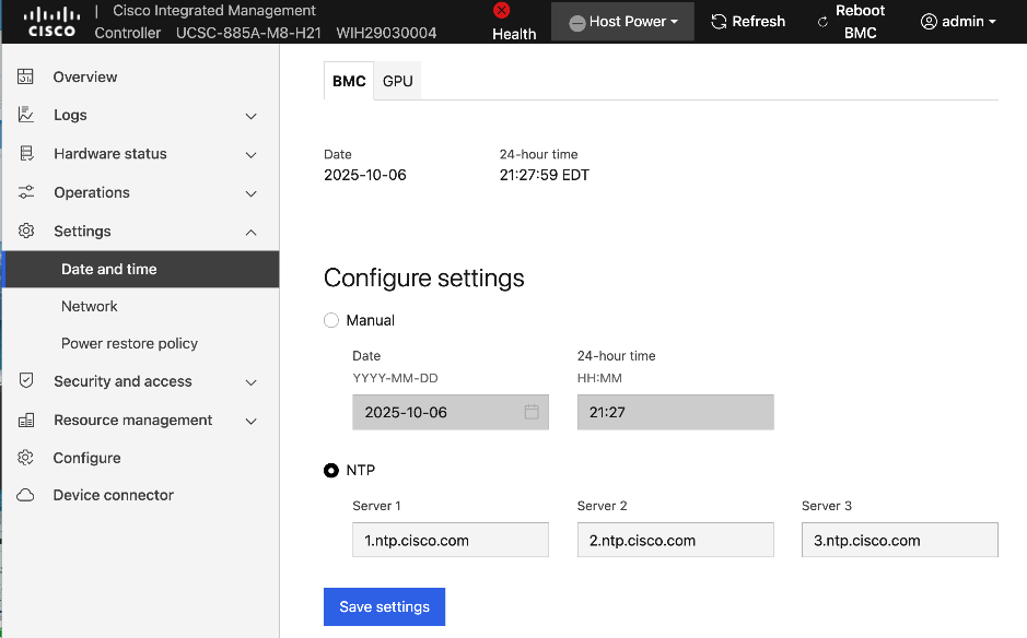
Step 4. Click Save settings.
Setup DNS
To configure DNS, complete the procedures below using the setup information provided in this section.
Procedure 1. DNS setup
Step 1. From a browser, go to the BMC IP address of the Cisco UCS C885A node and log in.
Step 2. From the left navigation menu, select Settings > Network. Scroll down to the Static DNS section.
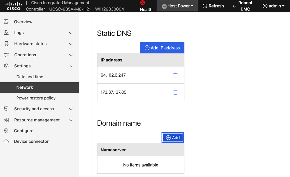
Step 3. Click Add IP address to add a DNS entry.
Step 4. Repeat this procedure for additional entries.
Step 5. (Optional) Specify a domain name for the CIMC interface in the Domain name section.
Configure Security and Access Policies
To configure Security and Access policies, complete the procedures in this section.
Procedure 1. Security and access policies configuration
Step 1. From a browser, go to the BMC IP address of the Cisco UCS C885A node and log in.
Step 2. From the left navigation menu, select Security and access > Policies. Enable both BMC shell (via ssh) and Network IPMI (out-of-band IPMI).
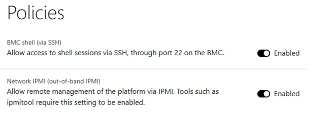
Configure BIOS Settings
To configure BIOS Settings, complete the procedures in this section.
Procedure 1. BIOS setting configuration
Step 1. Use a browser to go to the BMC IP address of the UCS C885A node and log in.
Step 2. From the left navigation menu, select Configure > Configure BIOS.
Step 3. Select the I/O tab. Configure settings as shown without selecting Reboot Host Immediately. If any changes are made, click Save.
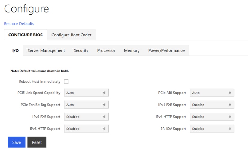
Step 4. Select the Server Management tab. Configure settings as shown without selecting Reboot Host Immediately. If any changes are made, click Save.
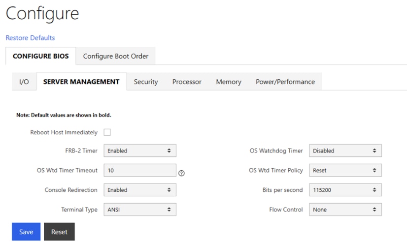
Step 5. Select the Security tab. Configure settings as shown without selecting Reboot Host Immediately. If any changes are made, click Save.
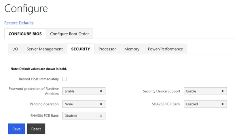
Step 6. Select the Processor tab. Configure settings as shown without selecting Reboot Host Immediately. If any changes are made, click Save.
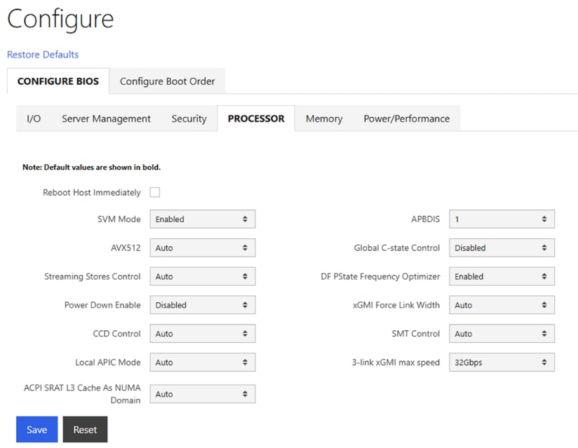
Step 7. Select the Memory tab. Configure settings as shown without selecting Reboot Host Immediately. If any changes are made, click Save.
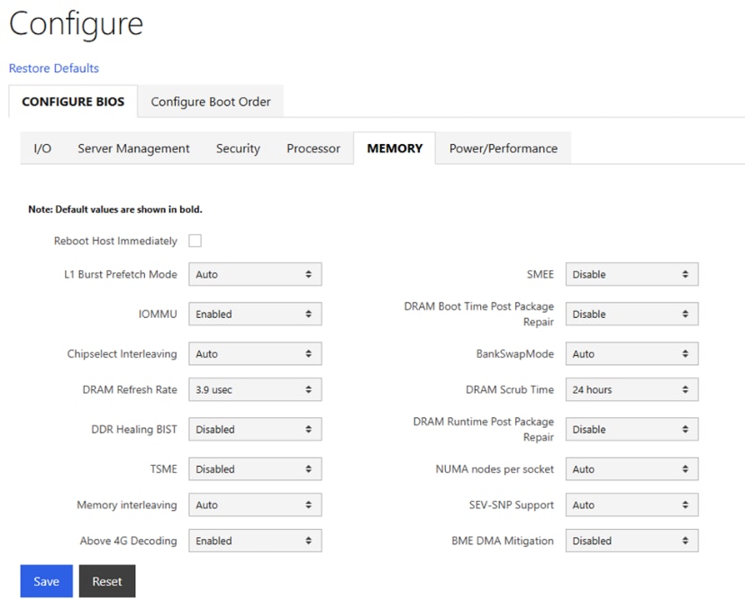
Step 8. Select the Power/Performance tab. Configure settings as shown and select Reboot Host Immediately. Click Save.
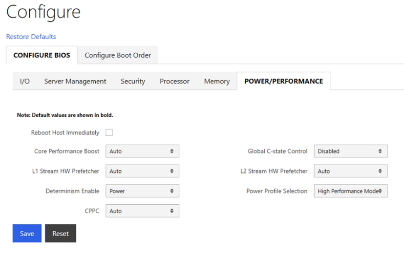
Set up Intersight Management – Claim and add Cisco UCS C885A Nodes in Cisco Intersight
To configure Cisco UCS C885A for Intersight management, complete the procedures below using the setup information provided in this section.
Procedure 1. Claim and add UCS C885A nodes in Cisco Intersight
Step 1. From a browser, go to the BMC IP address of the Cisco UCS C885A node and log in.
Step 2. From the left navigation menu, select Settings > Device Connector.
Step 3. Click Settings from the top menu bar.
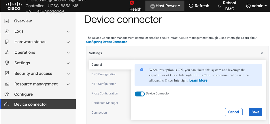
Step 4. In the General section, enable Device Connector and click Save.
Step 5. In the DNS and NTP Configuration sections, verify the previously configured settings.
Step 6. (Optional) In the Proxy Configuration section, specify a proxy if required for internet access.
Step 7. In the Certificate Manager section, import certificates as needed.
Step 8. In the Connection section, check connectivity to Intersight instance (EMEA or North America).
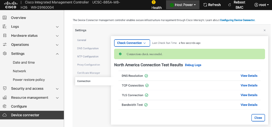
Step 9. Click Close.
Step 10. From the left navigation menu, go back to Device Connector and collect Device ID and Claim Code. Save this info temporarily.
Step 11. From a browser, go to intersight.com and log in to your intersight account.
Step 12. From the left navigation menu, select System > Targets. Click Claim a New Target.
Step 13. Select UCS Standalone Server.
Step 14. Click Start.
Step 15. Paste the Device ID and Claim Code here that was copied from the UCS C885A CIMC GUI.
Step 16. Click Claim.
Step 17. Return to UCS C885A’s BMC and check the status. It should have a status of Claimed.
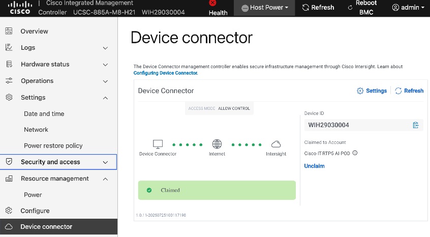
Step 18. Repeat steps 1 – 17 for the remaining Cisco UCS C885A nodes. You should now see all nodes as Targets in Intersight.
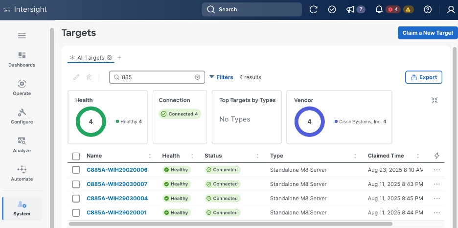
Step 19. Once the server is claimed into Intersight, it will appear under Operate > Servers. Server Inventory and Metrics can be viewed and the server’s BMC and KVM interfaces can be brought up from Intersight. In order for either of these interfaces to be reached, the machine that is logged into Intersight must have routable access to the C885As’ BMC IP addresses.
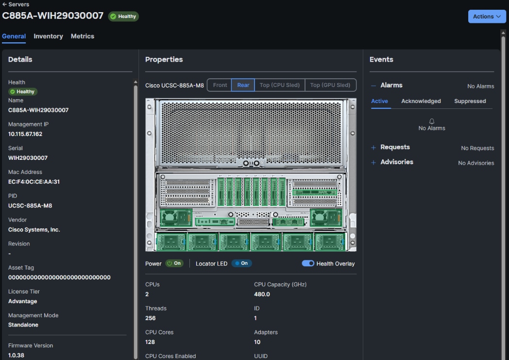
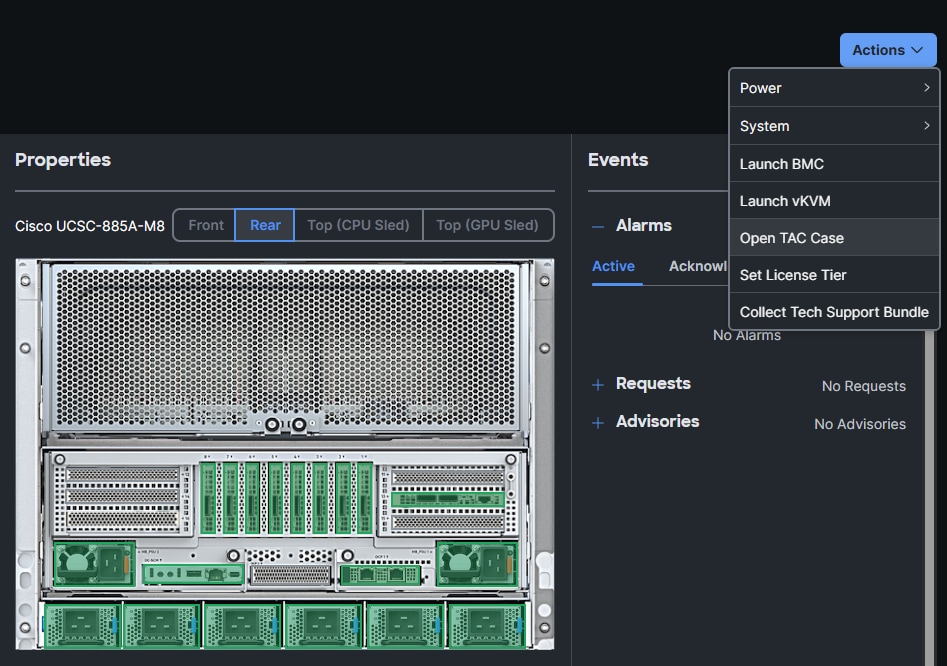
Collect MAC address for Frontend NIC(s) on all Cisco UCS C885A Nodes
You can collect the NIC and MAC information for all frontend NICs on UCS C885A from either Intersight or CIMC. Procedures for both are provided in this section.
To collect MAC address information via Intersight, follow the procedures in this section.
Procedure 1. Collect MAX information using Cisco Intersight
Step 1. From a browser, go to intersight.com and log in using your account
Step 2. From the left navigation pane, select Operate > Servers.
Step 3. Select the hostname for the Cisco UCS C885A node from the server list.
Step 4. Select the Inventory tab. Expand Network Adapters section and select the FHHL NIC used as your primary N-S NIC and IP for your OpenShift cluster.
Step 5. In the right window, select the Interfaces tab. Note the MAC Address of DCE 1 interface.
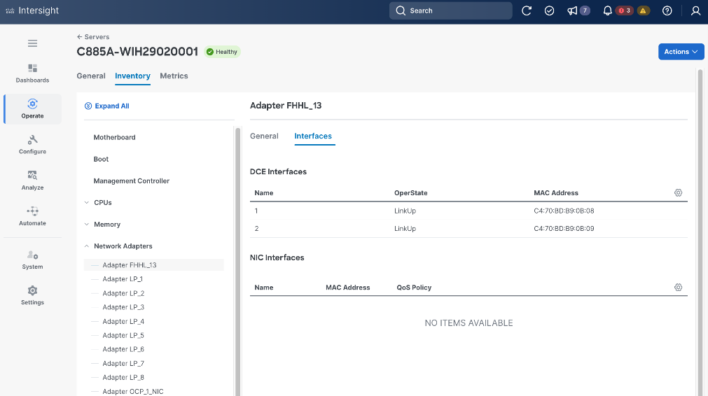
Procedure 2. Collect MAC information using Cisco BMC
Step 1. From a browser, go to the BMC IP address of the Cisco UCS C885A node and log in.
Step 2. From the left navigation menu, select Hardware status > Inventory and LEDs.
Step 3. Go to Network Adapters and select the frontend (N-S) FHHL NIC used as your primary NIC (OpenShift cluster IP). The ‘13’ in the NIC ID: FHHL_13 indiciates that this NIC is in slot 13.
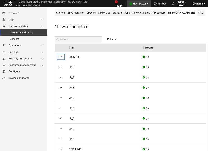
Step 4. Click the arrow to expand this NIC.
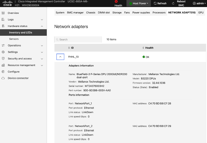
Step 5. Note the MAC address of first port i.e. NetworkPort_1.
Step 6. Repeat this procedure to collect mac-addresses for all UCS C885A nodes. Save this information.
Setup NIC Mode on NVIDIA BlueField-3 NICs
NVIDIA BlueField-3 NICs will need to be in NIC mode when using a LACP bond to connect to the frontend (N-S) fabric.
Procedure 1. NIC mode on NVIDIA BlueField-3 NICs setup
Step 1. From a browser, go to the BMC IP address of the Cisco UCS C885A node and log in.
Step 2. From the left navigation pane, select Operations > KVM.
Step 3. Click Launch KVM.
Step 4. In the KVM window, from the Host Power drop-down list, power-cycle the server.
Step 5. When you see the following, press ESC to enter setup.
Step 6. Use arrow keys to select Advanced tab from the menu bar.
Step 7. Use arrow keys to go down the list and select the first NVIDIA BlueField Network Adapter.
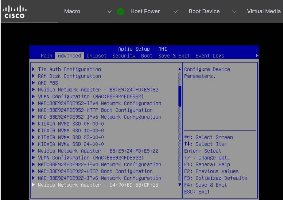
Step 8. Press Enter. Use arrow keys to select BlueField Internal CPU Configuration.
Step 9. Select Internal Cpu Offload Engine. Use arrow keys to disable this setting.
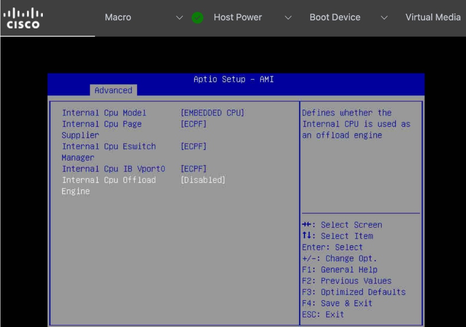
Setup Ethernet mode on NVIDIA CX-7 NICs
If you need to change the NVIDIA NICs from InfiniBand to Ethernet mode, follow the procedures in this section.
Procedure 1. Ethernet mode on NVIDIA CX-7 NICs setup
Step 1. From a browser, go to the BMC IP address of the Cisco UCS C885A node and log in.
Step 2. From the left navigation pane, select Operations > KVM.
Step 3. Click Launch KVM.
Step 4. In the KVM window, use the Host Power drop-down list from the top menu to power-cycle the server.
Step 5. When you see the following, press ESC to enter setup.

Step 6. Use the arrow keys to select Advanced tab from the menu bar.
Step 7. Use the arrow keys to go down the list and select the NVIDIA Network Adapter.

Step 8. Press Enter. Select the Network Link Type setting and change it to Ethernet
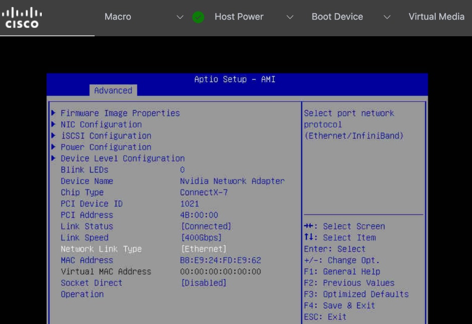
Step 9. Repeat steps 1 – 8 to change the settings on any remaining NVIDIA BlueField-3 or CX-7 adapters.
Step 10. Go to Save & Exit to Save Changes and Exit BIOS setup.
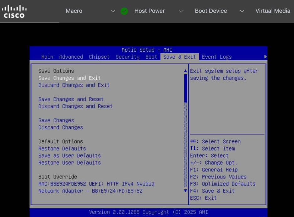
Create a Bare Metal Host Machine configuration file
To create Bare Metal Host (BMH) machine configuration files for each Cisco UCS C885A node being added to the OpenShift cluster, complete the procedures in this section. You will need the previously collected frontend NIC MAC address info. The OpenShift installer VM will also be used in this procedure.
Procedure 1. Setup bare metal host machine configuration file
Step 1. SSH into OCP Installer machine to create the configuration file. You can also create this file elsewhere but all configuration files are saved on this machine so it can be easily deployed to the cluster. Back up these files in case if you need it in the future.
Step 2. Go to the previously created cluster directory and then to machine-configs sub-directory.
Step 3. Create the following YAML file. Specify a name and provide the previously collected MAC address from the node as the bootMACAddress. Save it using a unique file name, one for each Cisco UCS C885A node.
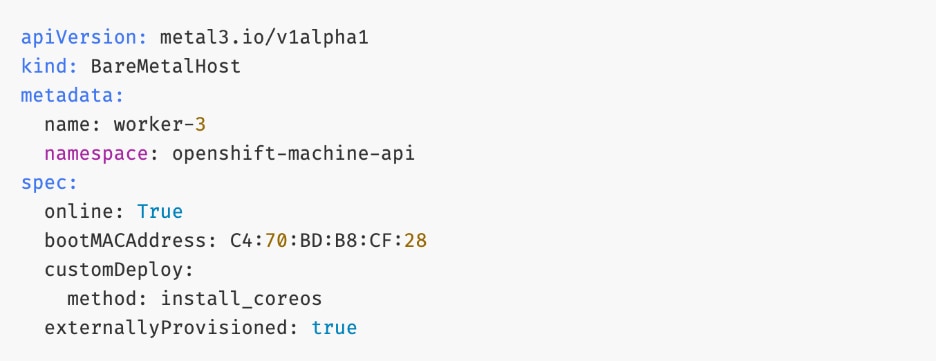
Step 4. Save and exit. We will deploy this file later in the deployment process.
Step 5. Repeat this procedure for each Cisco UCS C885A node that will be added to the cluster.
Verify Redfish access to Cisco UCS C885A Server
Procedure 1. Redfish access to Cisco UCS C885A server verification
Step 1. SSH into OpenShift Installer machine.
Step 2. Run the following command:
curl -k -u admin:'my_password' -H 'content-type: application/json' -X GET https://10.115.67.164/redfish/v1/Systems/system
Step 3. Sample output from the setup is shown below:
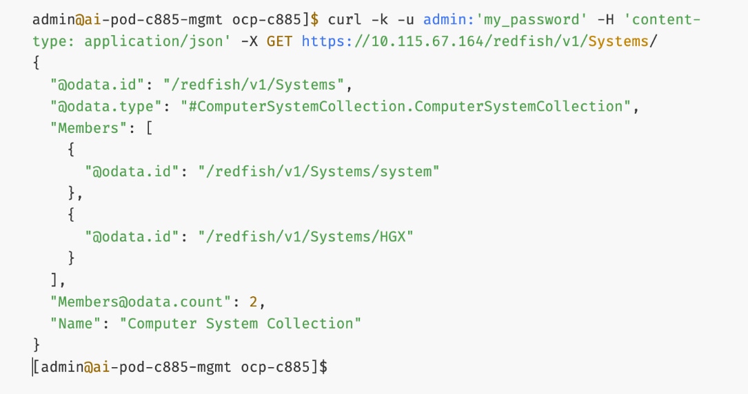
Step 4. You can further drill down using data.id values from above. For example:
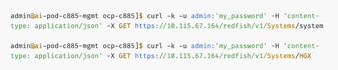
Upgrade Firmware
It is important to update Cisco UCS C885A firmware to at least the Suggested Release from https://software.cisco.com/download/home/286337202/type/283850974/release/1.1(0.250025). This procedure will show an update to what is currently the latest release – version 1.2(0.250011). The firmware will need to be updated individually on each server. The firmware downloads include a PCIe Switch Update Tool to update the PCIe switches between the GPUs and backend NIC cards, a server firmware upgrade script to update mainly BIOS and BMC firmware, a firmware tar.gz file containing the updated firmware, and a firmware hardware update utility ISO to update firmware in all hardware NICs in the server.
Note: At the time of publication, only the version 1.2 firmware includes the PCIe Switch Update Tool.
Procedure 1. Firmware upgrade
Step 1. Download all the desired Cisco UCS C885A M8 firmware release files from https://software.cisco.com.
Step 2. If your download included The PCIE Switch Update Tool, it can be run on Ubuntu 22.04.5 LTS or on RHEL 9.4, since Red Hat CoreOS 4.16-4.18 is based off RHEL 9.4, the PCIe switch update can be done from CoreOS. To upgrade the PCIe switch software with Red Hat CoreOS 4.18, from the OpenShift Installer VM where the pcie-switch-update-tool-04.18.00.00.zip file was downloaded to, run the following:
unzip pcie-switch-update-tool-04.18.00.00.zip
chmod +x pcie-switch-update-tool-04.18.00.00.run
scp pcie-switch-update-tool-04.18.00.00.run core@<c885a-hostname-or-IP>:/var/home/core/
ssh core@<c885a-hostname-or-IP>
sudo ./pcie-switch-update-tool-04.18.00.00.run
Enter option 1. If the Firmware Version is less than 04.18.00.00, then rerun the tool and select option 2.
If option 2, was entered, answer yes to the question.
Step 3. When the update is completed, drain the node and reboot the node. SSH back into the node and rerun the tool to verify the firmware update.
Step 4. The C885A BIOS and BMC update can be done from a Linux machine. In this example, it was done from the OpenShift Installer VM running RHEL 9.6. For this update, power off the C885A.
sudo dnf install python3.11
pip3.11 install prettytable
tar -xzvf ucs-c885a-m8-upgrade-script-v1.5.tar.gz
python3.11 ucs-c885a-m8-upgrade-v1.5.py -B ucs-c885a-m8-1.2.0.250011.tar.gz -U <user> -P <password> -I <BMC-IP> -D
Step 5. If any of the firmware components require update:
python3.11 ucs-c885a-m8-upgrade-v1.5.py -B ucs-c885a-m8-1.2.0.250011.tar.gz -U <user> -P <password> -I <BMC-IP> -F
Note: The update will take at least 15 minutes to complete.
Step 6. To upgrade the remaining firmware on the server, launch the server’s KVM interface. To launch the KVM from Intersight, select Operate > Servers.
Step 7. Click the ellipses to the right of the UCSC-885A-M8 server and select Launch vKVM. To launch the KVM from the BMC interface, select Operations > KVM and click Launch KVM. Once in the KVM window, use the Virtual Media pulldown and Map image to map the HUU ISO file to the KVM.
Step 8. From the Boot Device drop-down list to select a one-time boot from CD.
Step 9. From the Host Power drop-down list, power cycle the C885A and reboot from the HUU ISO CD.
Step 10. Follow the prompts to update the remaining firmware.
Add Cisco UCS C885A GPU Servers to OpenShift Cluster
The OpenShift cluster is deployed the Red Hat-recommended Assisted Installer from Red Hat's SaaS platform (Hybrid Cloud Console), as described in the previous section. In this section, Cisco UCS C885A GPU nodes will be added as worker nodes to the same cluster. As of this writing, there are specific differences in networking, Intersight integration, and other features that make the process of adding Cisco UCS C885A nodes to an OpenShift cluster distinct from that of other Cisco UCS worker nodes.
Note: Cisco UCS C885A nodes should be deployed as worker nodes in an OpenShift cluster. Other Cisco UCS nodes, such as Cisco UCS X-series and Cisco UCS C-2xx series, can be deployed as control nodes, worker nodes or both.
The OpenShift Cluster is deployed as a compact cluster using a Cisco UCS X-series Direct chassis, with Cisco UCS servers operating as both control and worker nodes. The Cisco UCS servers are also running OpenShift Virtualization and host the management VM components needed to support the OpenShift environment. The Cisco UCS C885A nodes will be added as additional worker nodes to this cluster.
The procedures in this section:
● Add Cisco UCS C885A nodes to the OpenShift cluster from Red Hat Hybrid Cloud Console. The networking configuration is specified using Static IP, bridges and bondsStatic IP, bridges and bonds option in the Assisted Installer. The two ports on the FE NIC are configured as an LACP bond with the OpenShift Cluster IP VLAN added as trunked VLAN to this bond. You will need the mac address of both FE interfaces previously collected.
● Set up UCS server as a bare metal host from OpenShift cluster console.
● Provision power management for Cisco UCS C885A using Redfish.
Assumptions
● Cisco Intersight Account and licenses to manage the Cisco UCS C885A servers in the OpenShift cluster.
● Red Hat Account to access Red Hat Hybrid Cloud Console (console.redhat.com).
● DNS, DHCP server deployed and provisioned for the Cisco UCS C885A worker nodes.
● Red Hat OpenShift cluster has been deployed. Cisco UCS C885A nodes will be added to this cluster.
● Out-of-band CIMC access to the Cisco UCS C885A nodes has been setup.
● Intel OCP NIC on each server has been setup for SSH access from a directly connected workstation (jump host). In an OpenShift deployment, the workstation must be on the same subnet (not routed) as the Intel NIC. This provides backup access to the nodes in the event of a networking issue.
Setup Information
Table 29 lists the setup parameters and other information necessary for the procedures in this section.
Table 29. Cisco UCS C885A: CIMC IP Access Details
| UCS Node |
CIMC/KVM IP Address |
Access Info |
| UCS C885A-1 |
10.115.67.161 |
< username/password > |
| UCS C885A-2 |
10.115.67.162 |
< username/password > |
| UCS C885A-3 |
10.115.67.163 |
< username/password > |
| UCS C885A-4 |
10.115.67.164 |
< username/password > |
Table 30 lists the previously deployed OpenShift cluster info in which the Cisco UCS C885A will be added.
Table 30. Cisco UCS C885A: OpenShift cluster Info
| Variable |
Info |
Additional Info |
| OCP Installer VM |
10.115.90.65 |
< username/password > |
| OCP Cluster Name |
ocp-c885.aipod.local |
Hybrid Cloud Console |
| OCP Cluster Console URL |
https://console-openshift-console.ocp-c885.aipod.local |
< username/password > |
| SSH Keys |
< collect > |
From installer VM or any other mgmt. nodes with SSH access |
Deployment Steps
To add a Cisco UCS C885A server to an existing OpenShift Cluster, use the procedures outlined below. Repeat the procedure to add more UCS C885A nodes to the same cluster.
Add Cisco UCS C885A Node to the OpenShift Cluster from Red Hat Hybrid Cloud Console
Procedure 1. Add Cisco UCS C885A node to the OpenShift Cluster
Step 1. From a browser, go to Red Hat Hybrid Cloud Console (HCC) at console.redhat.com and log in with your account.
Step 2. Go to Red Hat OpenShift tile and click OpenShift.
Step 3. From the left navigation menu, under Cluster Management, click Cluster List.
Step 4. Find your cluster in the list and click the cluster name.
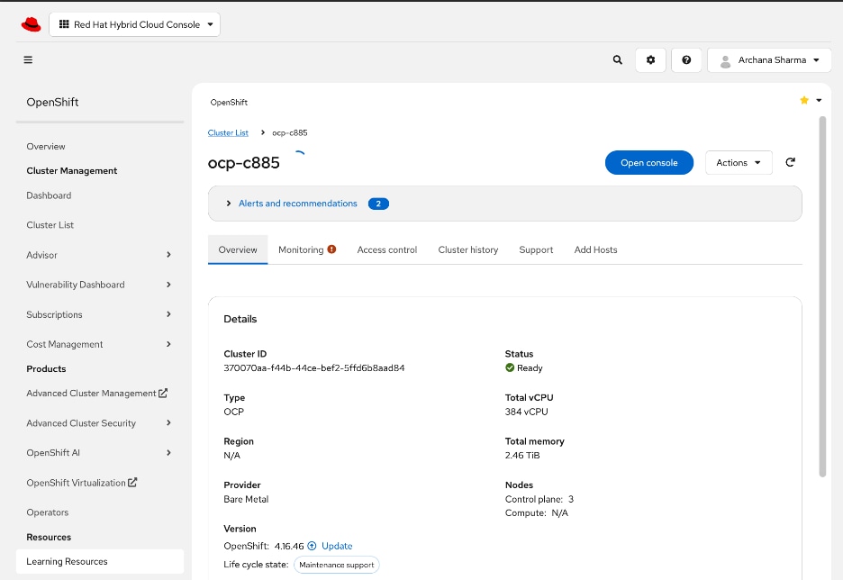
Step 5. Select the Add Hosts tab.
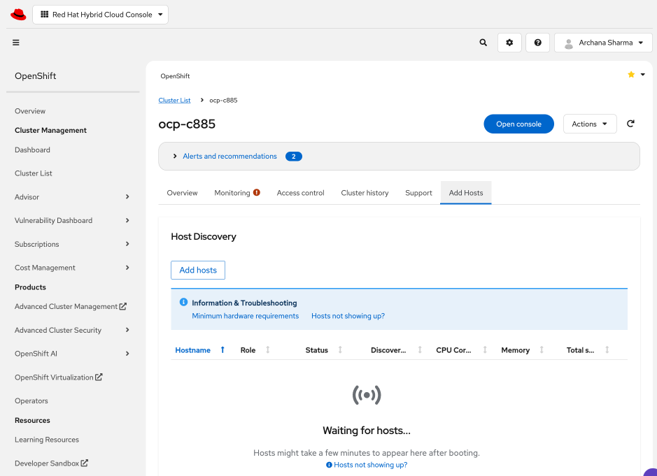
Step 6. Click Add Hosts box in the Host Discovery section.
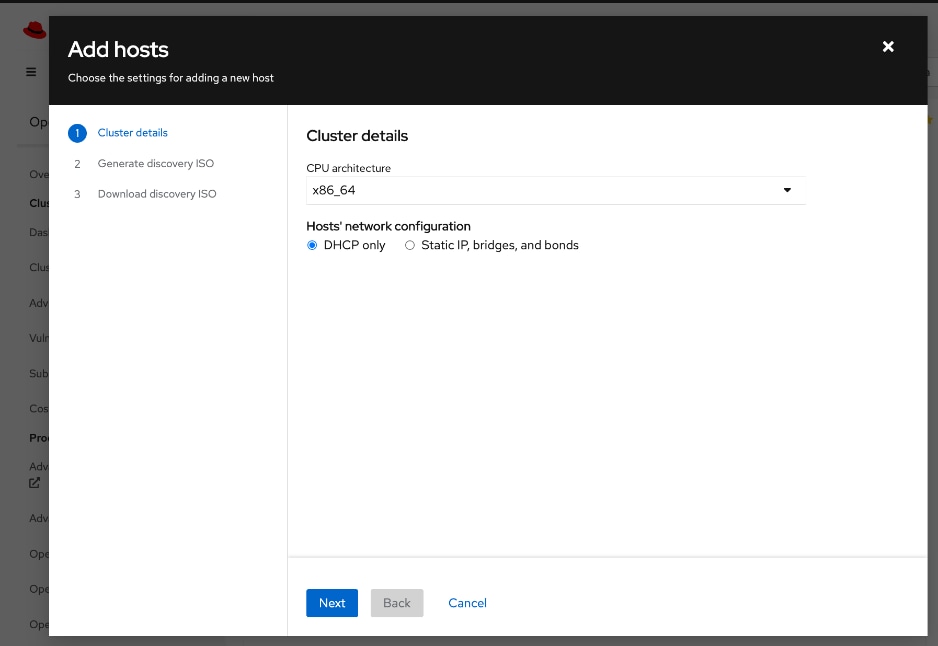
Step 7. Select Static IP, bridges, and bonds. Click Next.
Step 8. Select the radio button for YAML view to configure using YAML.
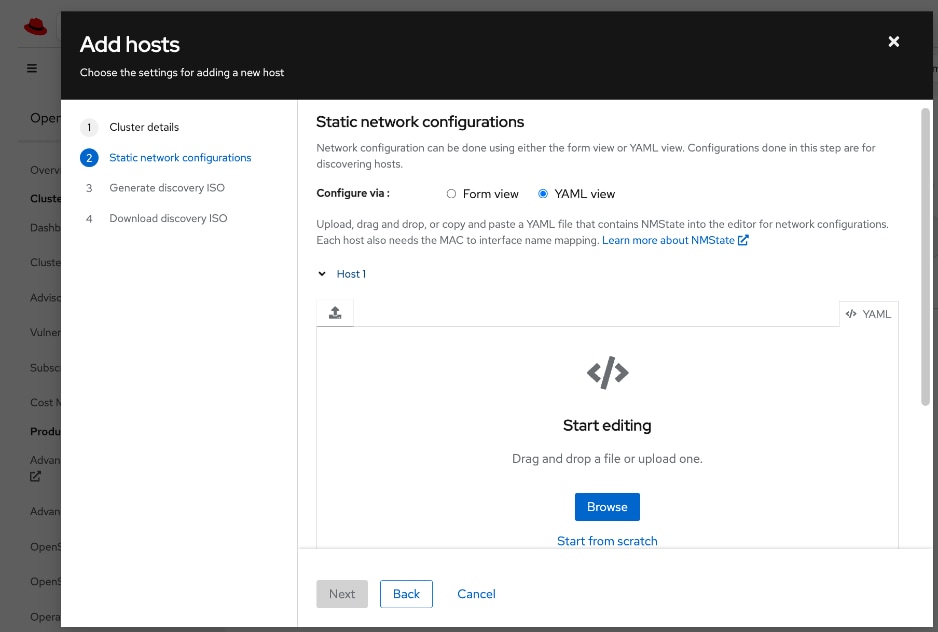
Step 9. Click Browse to upload a pre-defined YAML file or Start from scratch to configure it directly in the window. The static network configuration for the C885A in this setup is provided below. Note the interface names (derived from NIC ID/Slot) and that DHCP is enabled on the trunked VLAN on the bond and not on the bond itself in order to support both OpenShift Cluster IP management VLAN and Storage Access VLAN on the same frontend NIC. Adjust as needed for your deployment scenario.
interfaces:
- name: bond0
description: Bond with ports ens213f0np0 and ens213f1np1
type: bond
state: up
ipv4:
dhcp: false
enabled: false
ipv6:
enabled: false
link-aggregation:
mode: 802.3ad
options:
miimon: '100'
port:
- ens213f0np0
- ens213f1np1
mtu: 9000
- name: bond0.703
description: vlan 703 using bond0
type: vlan
state: up
vlan:
base-iface: bond0
id: 703
ipv4:
dhcp: true
enabled: true
mtu: 1500
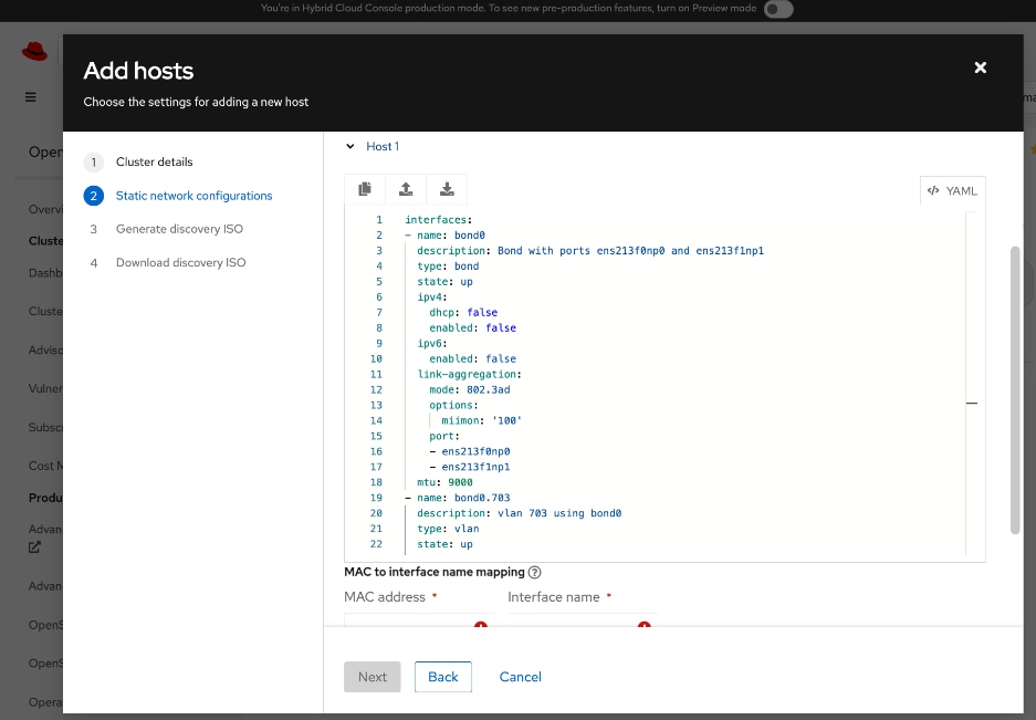
Step 10. Scroll down and provide MAC to Interface name mapping for both ports in the bond.
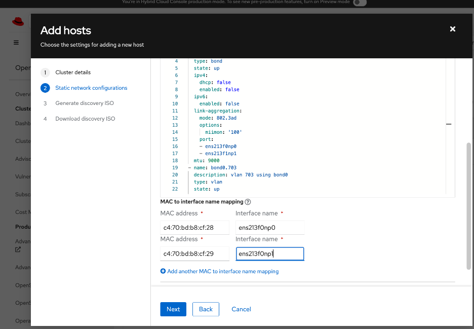
Step 11. Click Next.
Step 12. Specify whether to use minimal ISO (default) or Full ISO. Upload or paste SSH keys previously generated for the cluster from the Installer VM (~/.ssh directory).
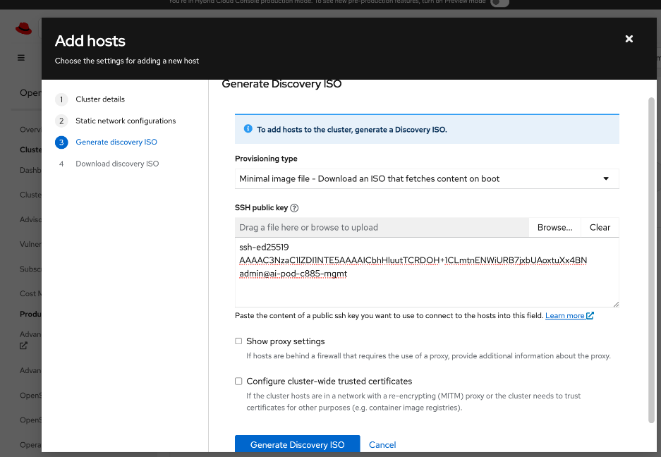
Step 13. Click Generate Discovery ISO.
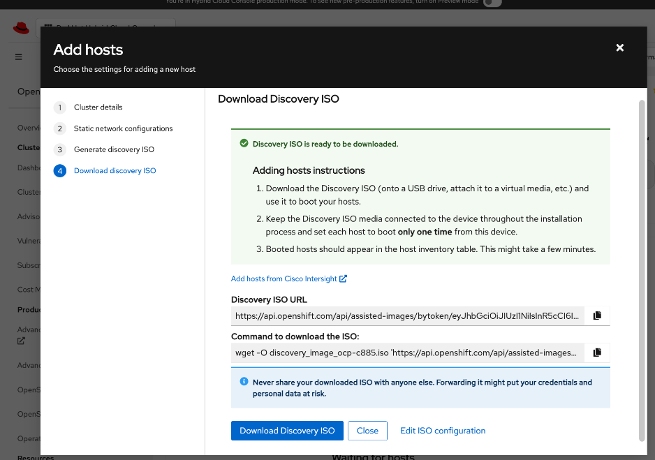
Step 14. Click Download Discovery ISO.
Step 15. Click Close.
Step 16. Go back to Cisco Intersight.
Step 17. From left navigation menu, go to Operate > Servers and select the UCS C885A from the list of servers. Click the server name.
Step 18. Click Actions and select Launch vKVM from the drop-down list.
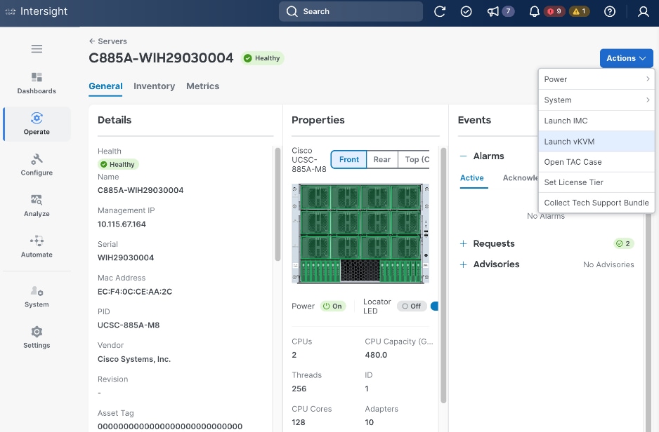
Step 19. In the vKVM window, go to Virtual Media in the top meny bar.
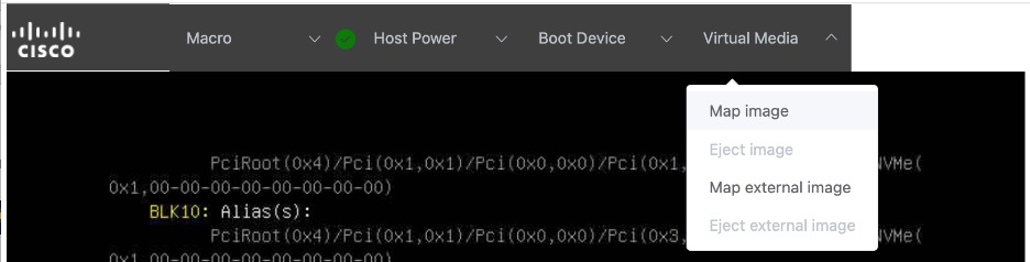
Step 20. Select Map image from the drop-down list.
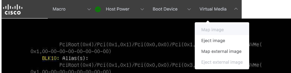
Step 21. Click Drop file here or click to upload. Select the previously downloaded Discovery ISO. Click Open. Click Upload.
Step 22. Go to Boot device in the top menu bar. Select CD from the drop-down list.

Step 23. Go to Host Power and select Power cycle from the drop-down list.
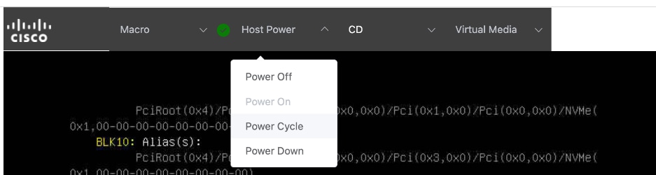
Step 24. Click Confirm in the pop-up window. The server will now reboot and load the Discovery ISO. Booting RHEL CoreOS (Live) shown below indicates that Discovery ISO is being loaded. If you have issues with loading discovery ISO from KVM console – see the next step.
Step 25. Skip this step if you can load the Discovery ISO as indicated by the message in the above screenshot. If not, go to CIMC of the node, log in and go to Configure > CONFIGURE BOOT ORDER. Find UEFI: Linux File-CD Gadget 0515 from the list. Use arrow-keys to move it to the top-of the list in the Expected Boot Order. If you don’t see this, try mounting the virtual media image from the KVM console again. Also, change one time boot device to CD and then select Reboot Host immediately. The CIMC menus on C885A can take some time to load so wait a few minutes for it to load completely.
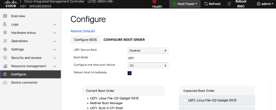
Step 26. Click Save Changes and monitor the booting process in the KVM console.
Step 27. Once the Discovery ISO boots up, you should see output like the one shown in the screenshot below. Verify hostname, interfaces, and IP address details are correct before proceeding.
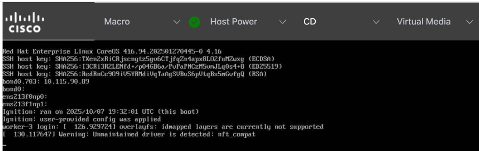
Step 28. Remove mapped Virtual Media image and Boot Device (set to None) if it did not automatically get disabled.
Step 29. From a browser, log back into Red Hat Hybrid Cloud Console. Go to OpenShift > Cluster List > <name_of_cluster> > Add Hosts. The newly added worker should show up after a few minutes. Wait for the Status to become Ready.
Step 30. Expand the newly added node and verify that the installation diskselected is the M.2 boot drive(~960GB drive). Also verify that the role, hostname and so on are correct and that NTP has synced.
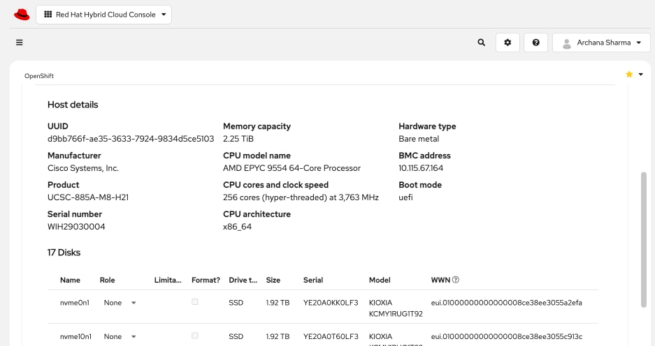
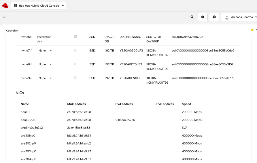
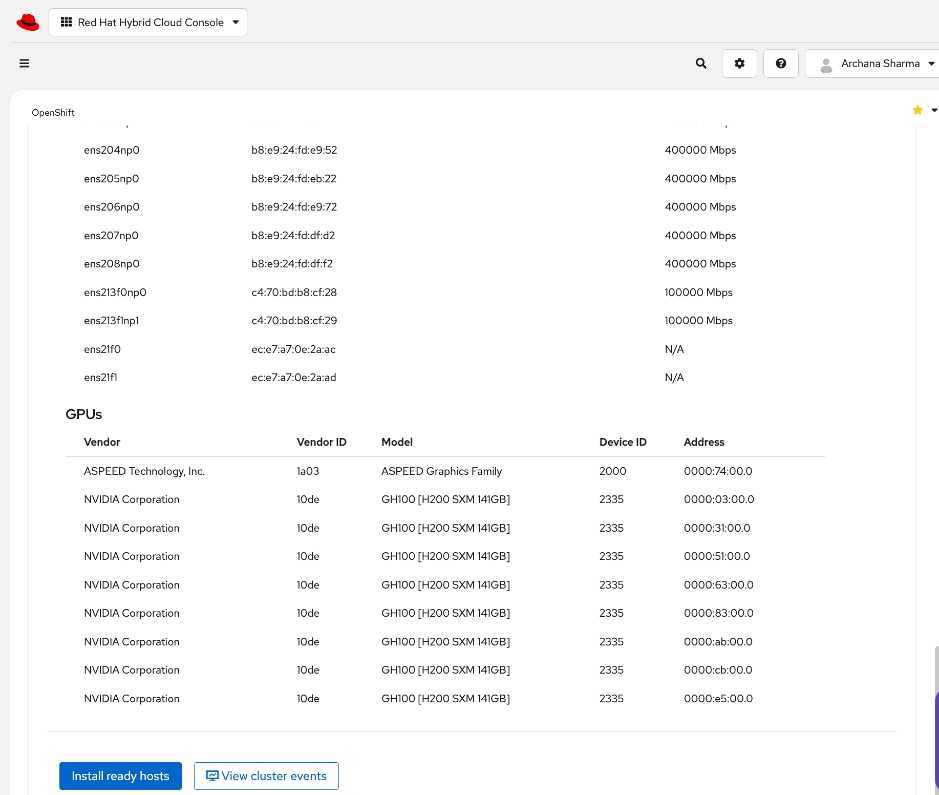
Step 31. Click Install ready hosts to complete the installation process.
Step 32. Click View cluster events to the view the installation process events from this view.
Step 33. Click Close.
Step 34. Once the installation completes, you should see a status of Installed. If not, the server may still be in the booting process.
Step 35. Go back to KVM console to monitor and verify installation status.
Step 36. Confirm that a Boot Device is not selected. Virtual Media also should not have an image mapped.
Step 37. Once the installation completes, you might see output similar to the screenshot below:
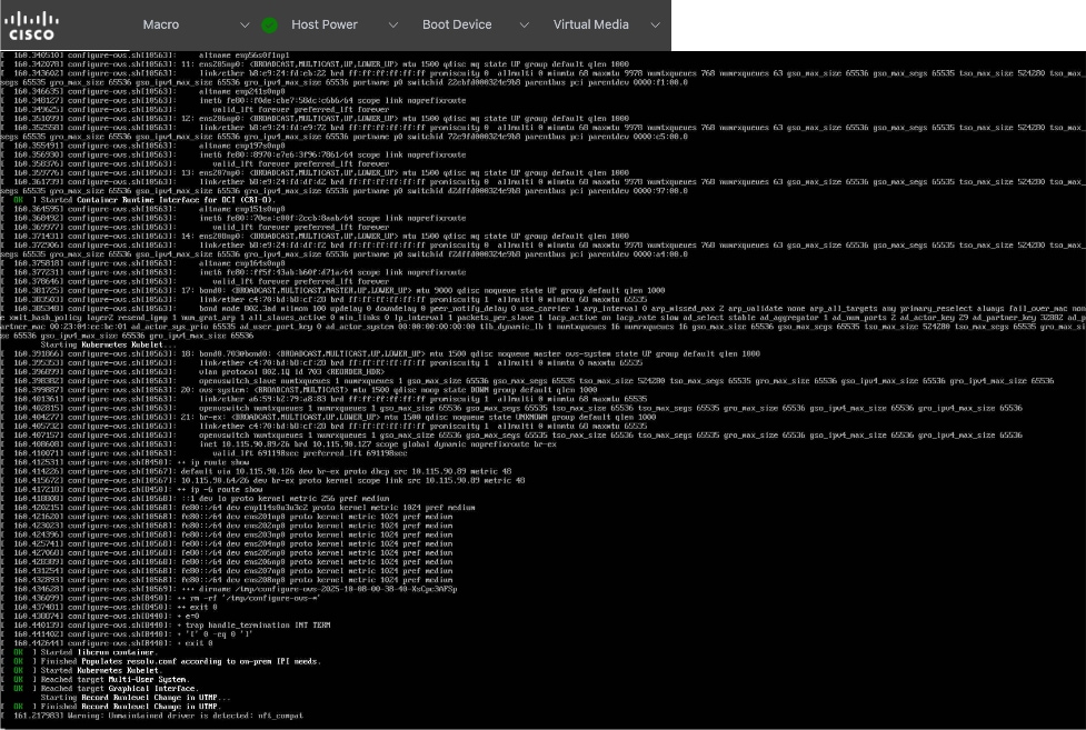
Step 38. Go back to CIMC for the server and go to Configure > CONFIGURE BOOT ORDER. Red Hat Enterprise Linux should now be at the top of both Current and Expected Boot Order columns.
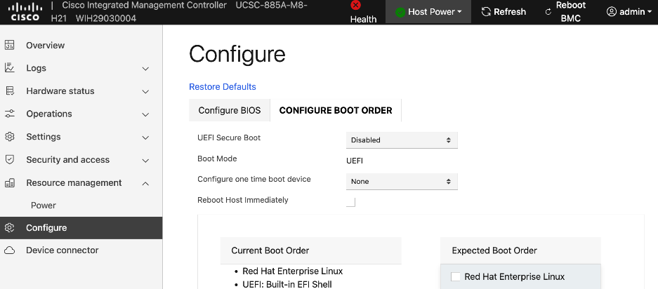
Step 39. Reboot/Power Cycle the server once more to make sure it boots the RHCOS image. Monitor progress from KVM Console.
Step 40. Once the node comes back online, go back to Red Hat Hybrid Cloud Console. Note the BMC IP address and mac-address for bond0/cluster IP.
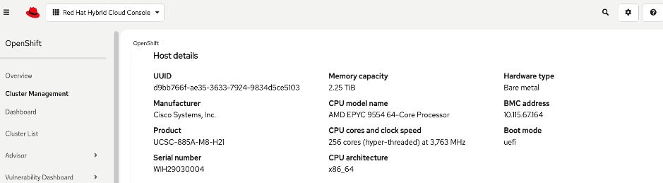
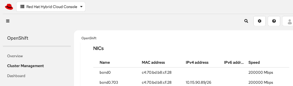
Step 41. With the OpenShift install on the node complete, go and log into the OpenShift Cluster Console to finish the remaining setup.
Set up UCS server as a Bare Metal Host from OpenShift Cluster Console
Procedure 1. UCS server as Bare Metal Host from OpenShift Cluster Console setup
Step 1. From a browser, log into the OpenShift Cluster Console.
Step 2. From the left navigation menu, select Compute > Bare Metal Hosts.
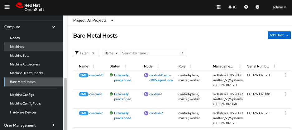
Step 3. For Project, select openshift-machine-api from the drop-down list.
Step 4. Click Add Host from the top right corner of the window. Select New with Dialog.
Step 5. Specify hostname of node. Provide bond0 MAC address (collected earlier) as Boot MAC Address. You can also apply BMH yaml file that you created in the Initial Setup of UCS C885A section. Disable power management for now. This will be enabled later, once the node has been added to the cluster successfully.
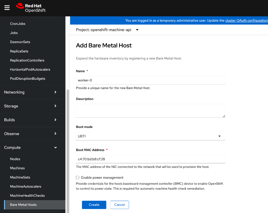
Step 6. Click Create.
Step 7. In the Bare Metal Host > Bare Metal Host Details window for this host, select YAML from the menu. Edit the YAML file and add externallyProvisioned: true in the spec: section as shown.
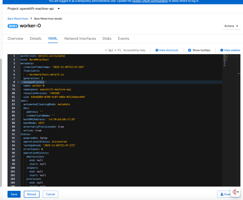
Step 8. Click Save and Reload.
Step 9. From the left navigation menu, go to Compute > Bare Metal Hosts to see a list of all hosts and their current state. The newly added host should have a status of Unmanaged with no power management.
Step 10. From the left navigation menu, go to Compute > Nodes. The new worker node should be in Discovered state. Click Discovered.
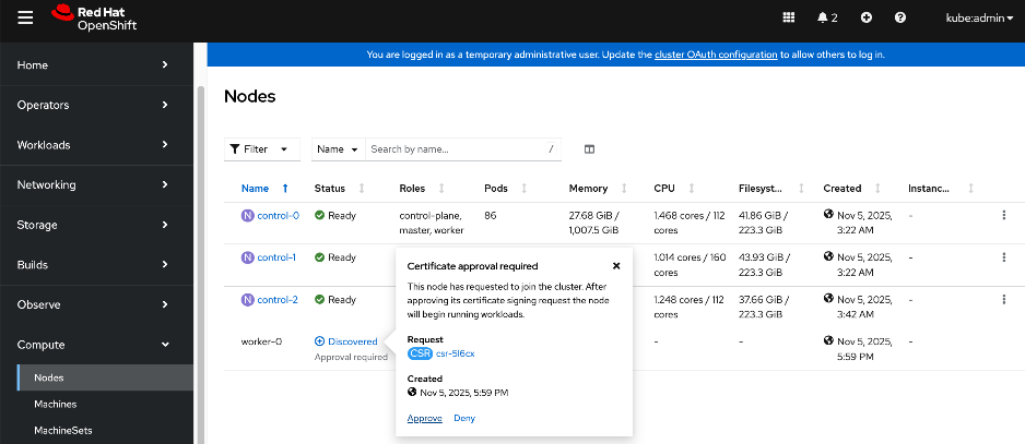
Step 11. Click Approve for the certificate signing request from the node to join the cluster.
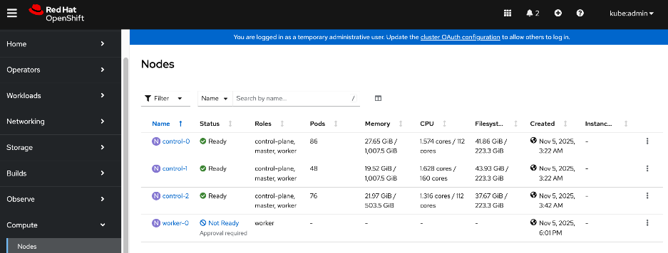
Step 12. Click Not Ready and click Approve again.
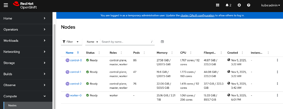
The status should now change to Ready.
Step 13. From the left navigation menu, go to Compute > Machinesets. Click the ellipses to the right of the machineset and select on Edit Machine Count from the menu.
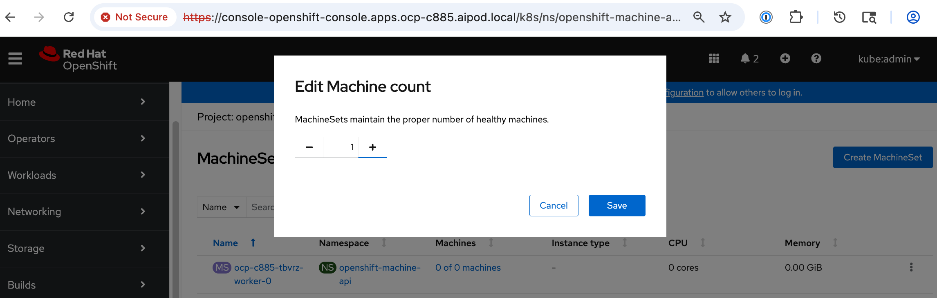
Step 14. In the pop-window, increment the count by 1 to add this one node. Click Save.
Step 15. From the left navigation menu, go to Compute > Machines. Note the last 5 characters in the hostname of the newly added machine.
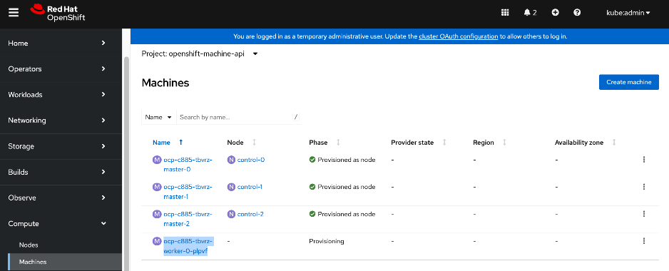
Step 16. From the left navigation menu, go to Compute > Bare Metal Hosts. Select another host (other than the node being added). Go to YAML tab and go to the spec section.
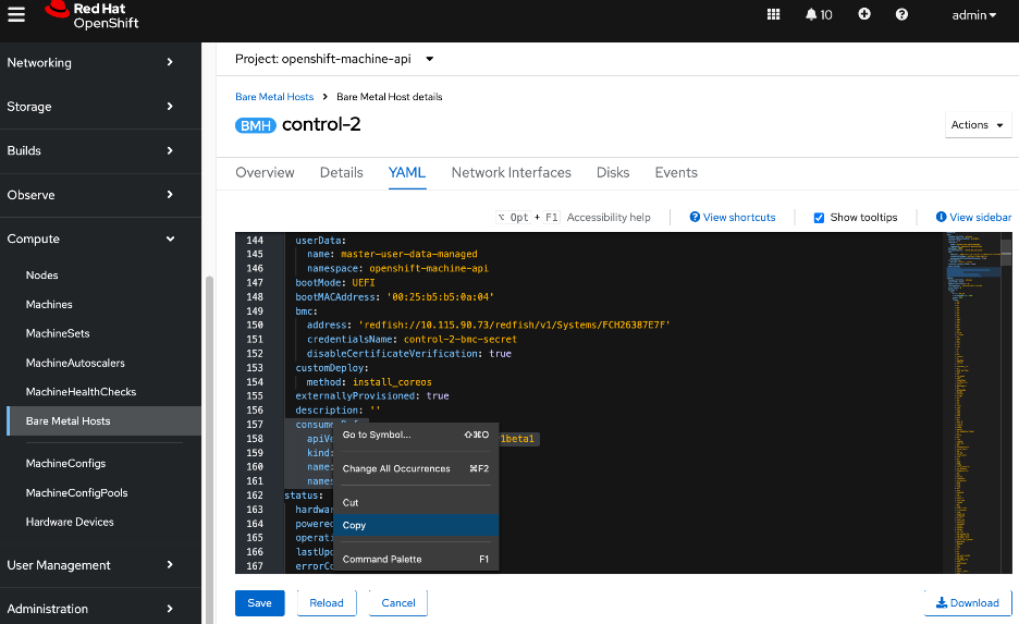
Step 17. Select and copy the consumerRef section from this host so that it can be pasted it into the spec section of the new host. Pay close attention to the spacing.
Step 18. Click Cancel. Go back to Bare Metal Hosts list and select the newly added node.
Step 19. Go to the YAML tab. Paste the above to the end of the spec: section. Edit the name to reflect the this node’s name by adding the 5 characters (saved earlier) to the end. Verify spacing is correct.
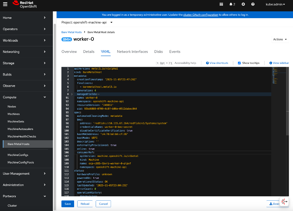
Step 20. Click Save and Reload.
Step 21. From the left navigation menu, go to Compute > Machines. The newly added machine should now show as Provisioned.
Step 22. Click the new machine and select the YAML tab. To link this machine to the node, copy the providerID from the machine YAML file.
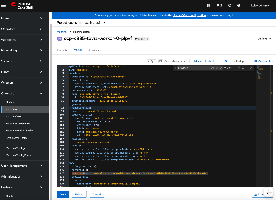
Step 23. From the left navigation menu, go to Compute > Nodes. Select the new node and edit its YAML file. Go to spec: section. Delete the {}, and then paste the providerID as shown. Note the spacing.
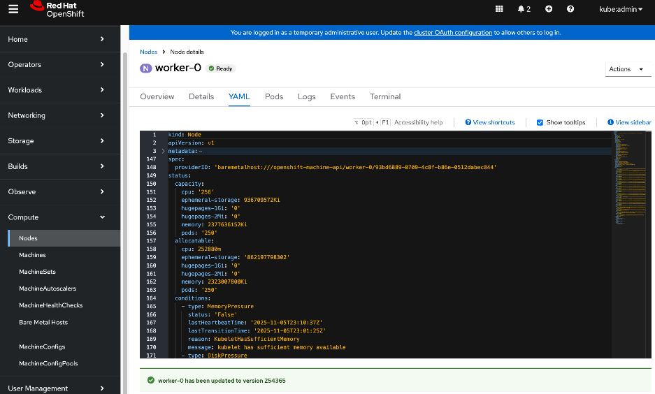
Step 24. Click Save and Reload.
Step 25. The baremetal host should now be linked to the node. Verify by navigating to Compute > Machines.
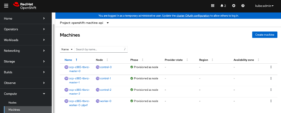
Step 26. The machineset should now show the newly added machine.
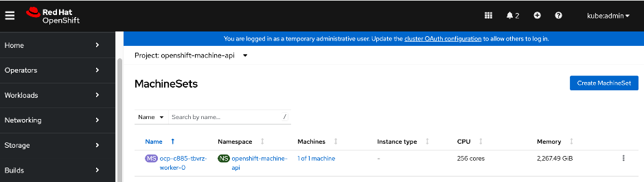
Step 27. Now that the node is added to the cluster, you can now provision the node for Power management.
Enable Power Management for Cisco UCS C885A using Redfish
Procedure 1. Configure Power Management for Cisco UCS C885A using Redfish
Step 1. From the left navigation menu, go to Compute > Bare Metal Hosts.
Step 2. Select the new host and click the ellipse to the right of the host. Select Edit Bare Metal Host from the menu.
Step 3. Click Enable Power Management. Specify the Redfish URL using BMC IP address collected earlier (for example: redfish://10.115.67.164/redfish/v1/Systems/system). Enable the checkbox to Disable Certificate Verifcation. Specify BMC Username and BMC Password.
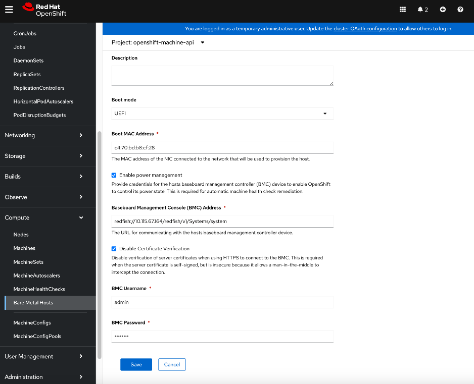
Step 4. Click Save. If it was successful, you will see the status of the new Bare Metal Host as Externally Provisioned.
![]()
Step 5. Repeat this procedure for the remaining Cisco UCS C885A worker nodes.
Set up Networking for Storage Access
The procedures in this section:
● Deploy Red Hat Kubernetes NMState Operator
● Setup networking for accessing storage using NFS
● Verify that the storage system is reachable from worker nodes
Red Hat NMState Operator will be used to configure the storage networking interfaces on the OpenShift worker nodes. Since the cluster was deployed as a compact cluster, this includes the control nodes which also function as worker nodes.
Note: The NMState Operator can be used to add or change networking on the OpenShift cluster though it is first deployed in this section to provision storage access networking on the UCS nodes.
Assumptions and Prerequisites
Setup Information
This information is provided in line with the deployment steps.
Deployment Steps
To setup networking on UCS worker nodes for NFS storage access, follow the procedures below.
Procedure 1. Deploy Red Hat Kubernetes NMState Operator
Step 1. From a browser, log into the OpenShift Cluster Console.
Step 2. From the left navigation menu, go to Operators > OperatorHub. In the search box, enter nmstate. Click the Kubernetes NMState Operator tile when it shows up.
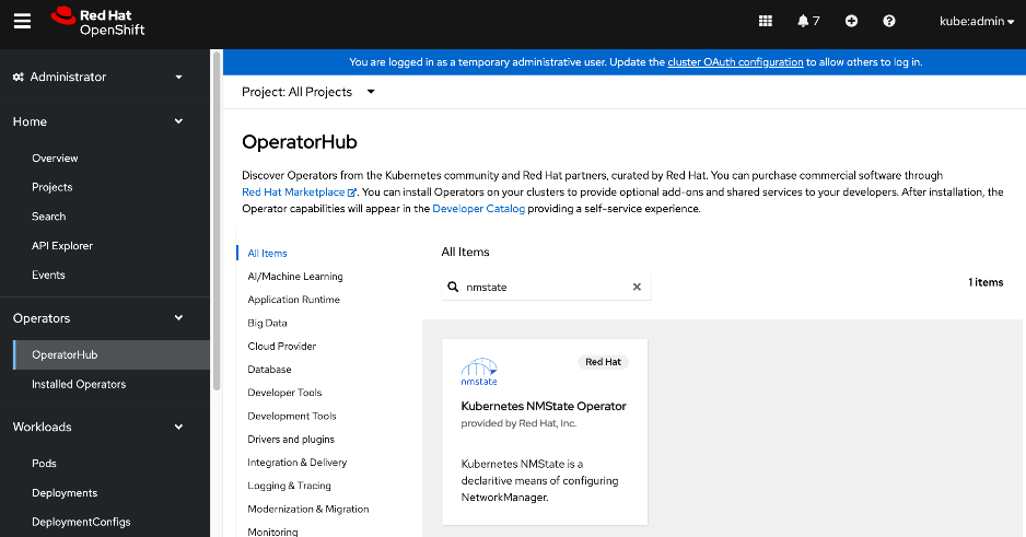
Step 3. Click Install. Leave everything as is. Click Install.
Step 4. Once the operator is installed, click View Operator.
Step 5. Scroll down to the bottom of the Details tab. Verify that the install completed successfully.
Step 6. Select the NMState tab.
Step 7. Click Create NMState. Use the defaults and click Create.
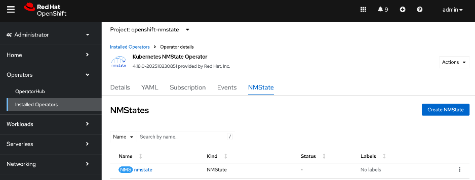
Configure UCS worker node(s) for NFS Storage Access
Procedure 1. UCS worker node(s) for NFD storage access setup
Step 1. Log into OpenShift installer workstation.
Step 2. Go to the machine-configs sub-directory In the cluster directory and create the following NodeNetworkingConfigurationPolicy file to deploy an NFS interface on the first worker node.
Note: If using DHCP, a single policy can be created and applied to all worker nodes.
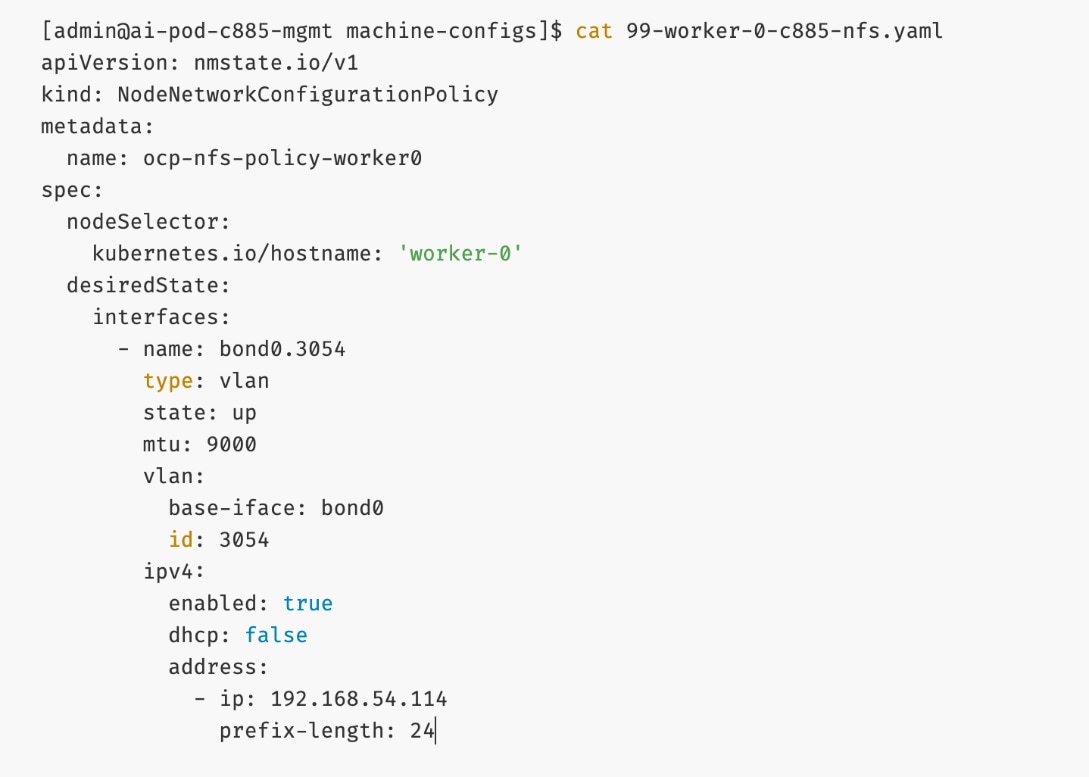
Step 3. Deploy the configuration policy to the OpenShift cluster:
oc create -f 99-worker-0-c885-nfs.yaml
Step 4. Repeat steps 1 – 3 for the remaining nodes in the cluster.
Step 5. From the left navigation menu, go to Networking > Node NetworkConfigurationPolicy. You should now see policies as shown.
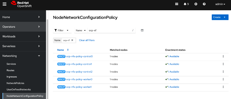
Step 6. Use ssh core@<node IP> to connect to each worker node and verify the configuration and setup using the commands below:
ip address show <interface_name>
ethtool <physical_interface_name>
ifconfig <interface_name>
Verify the connectivity to Everpure FlashBlade//S
Procedure 1. Connectivity to Everpure FlashBlade//S verification
Step 1. SSH into the OpenShift installer machine.
Step 2. Use ssh core@<node IP> to connect to the first worker node.
Step 3. Verify connectivity to Everpure FlashBlade by pinging its storage data interface from storage access interface on the UCS node.
Deploy Portworx to provide Persistent Storage
This section details the procedures for deploying and setting up Portworx by Everpure to provide persistent storage for AI (Kubernetes) workloads in Red Hat OpenShift. The persistent storage will be provisioned on Everpure FlashBlade//S using NFS.
The procedures in this section:
● Create API token on Everpure FlashBlade for use by Portworx
● Deploy Kubernetes secret to securely access Everpure FlashBlade
● Generate Portworx Enterprise Specification from Portworx Central
● Deploy Portworx Enterprise Operator from Red Hat OpenShift Cluster Console
● Verify that Portworx cluster is up and running in OpenShift
Assumptions and Prerequisites
● Everpure FlashBlade’s Management endpoint IP is reachable from all OpenShift nodes on the in-band management network.
● Network connectivity from UCS nodes to frontend fabric for accessing NFS datastores on Everpure FlashBlade has been setup.
● Everpure FlashBlade’s NFS Storage Data endpoint IP is reachable from all OpenShift nodes on the storage data network.
Setup Information
This information is provided in line with the deployment steps.
Deployment Steps
To deploy Portworx operator and setup Kubernetes networking to access storage, complete the procedures in this section using the setup information provided above.
Create User and API Token on Everpure FlashBlade for use by Portworx
Procedure 1. User and API token on Everpure FlashBlade setup
Step 1. From a browser, go Everpure management portal on Everpure FlashBlade and log in.
Step 2. From the left navigation menu, go to Settings > Users and Polices.
Step 3. In the Users section, click the ellipses. Select Create user… from the drop-down list to create a user and specify role as Storage Admin in Access Policies. This user will be associated with an API token that will be used to establish secure communication between Portworx Enterprise and Everpure Flashblade. The token serves as a key for Portworx to authenticate with FlashBlade and perform storage operations on behalf of the authorized user.
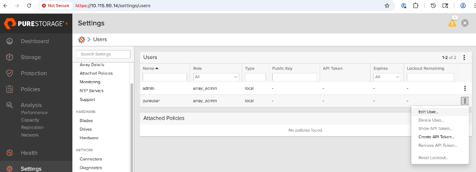
Step 4. Click the ellipses and select Create API Token.
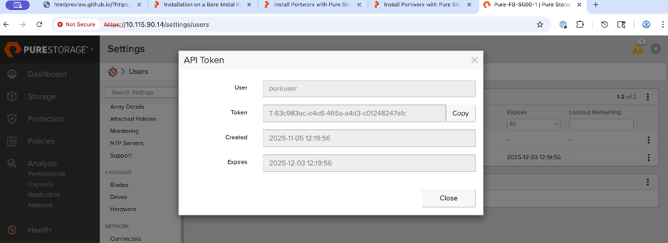
Step 5. In the API Token window, for Expires, specify the number of weeks (for instance 24) before the token expires. Leave this field blank if you don’t want the token to expire. Click Create. Copy and save the newly created API key as it will be used later to create a Kubernetes Secret for use by Portworx.
Create and Deploy Kubernetes Secret to Securely Access Everpure FlashBlade
Procedure 1. Kubernetes Secret to Securely Access Everpure FlashBlade setup
To establish secure communication between Portworx and Everpure FlashBlade, a Kubernetes secret is created to securely store the FlashBlade configuration details. This secret allows Portworx to access this information within the Kubernetes environment.
Step 1. SSH into the OpenShift installer workstation.
Step 2. Go to the OpenShift cluster directory. Create a sub-directory called portworx to save all portworx related configuration files.
Step 3. Create a JSON configuration file: pure.json containing key information from Everpure FlashBlade: Management IP address, API token for the authorized user, and NFS endpoint IP. You can add multiple NFS endpoints to the same file, from multiple Everpure FlashBlades or FlashArray. You can locate the IP information from the Everpure portal under Settings > Network Interfaces.
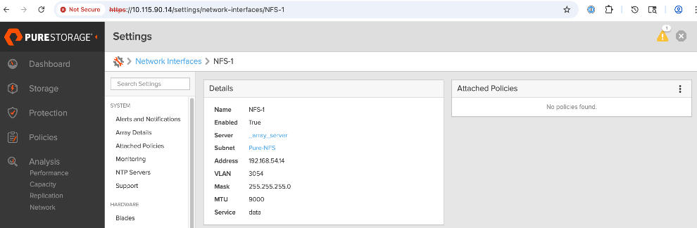
[admin@ai-pod-c885-mgmt portworx]$ vi pure.json
{
"FlashBlades": [
{
"MgmtEndPoint": "10.115.90.14",
"APIToken": "T-63c983ac-e4e6-465a-a4d3-c01248247afc",
"NFSEndPoint": "192.168.54.14"
}
]
}
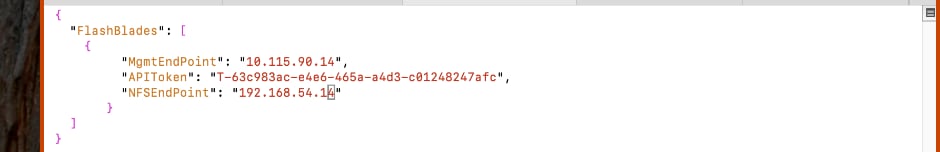
Step 4. Create and deploy Kubernetes secret using the above JSON file as shown. The secret must have the name: px-pure-secret so that Portworx can correctly identify and access the Kubernetes secret upon startup.
[admin@ai-pod-c885-mgmt portworx]$ pwd
/home/admin/ocp-c885/portworx
[admin@ai-pod-c885-mgmt portworx]$ ls
pure.json
[admin@ai-pod-c885-mgmt portworx]$ oc create secret generic px-pure-secret --namespace portworx --from-file=pure.json=/home/admin/ocp-c885/portworx/pure.json
secret/px-pure-secret created
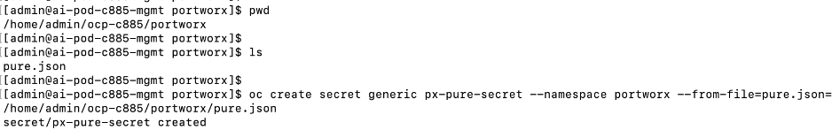
Step 5. Go back to the OpenShift cluster console. From the left navigation menu, go to Workloads > Secrets to verify the deployed configuration.
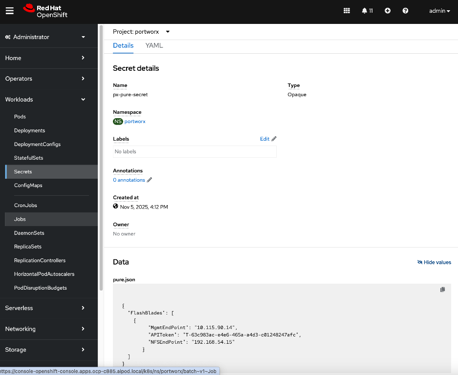
For more information on setting up Everpure FlashBlade as Direct Access Storage Backend for Portworx, see: https://docs.portworx.com/portworx-enterprise/platform/install/pure-storage/flashblade/prepare
Generate Portworx Enterprise Specification from Portworx Central
Procedure 1. Portworx Enterprise specification from Portworx Central setup
Step 1. From a browser, log into Portworx Central at https://central.portworx.com/landing/login.
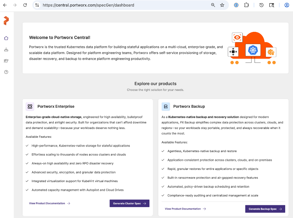
Step 2. In the Portworx Enterprise section, click Generate Cluster Spec.
Step 3. In the Generate Cluster Spec. wizard, in Step1: Select Your Platform section, for Platform, select ON-PREMISES > DAS/SAN from the drop-down list for using Everpure FlashBlade as the backend storage.
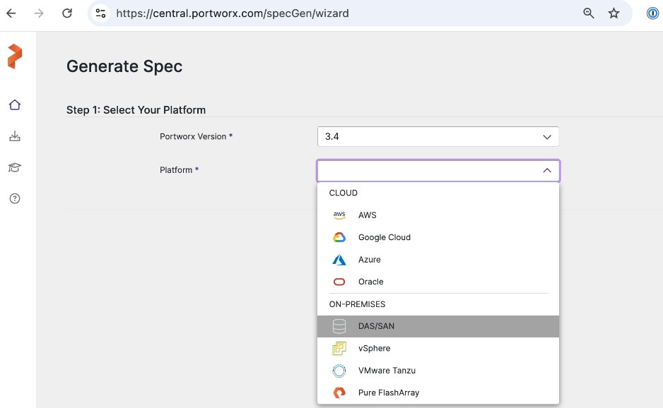
Step 4. In the Step 2: Kubernetes Distribution, for Distribution Name, specify OpenShift 4+ from the drop-down list. For Namespace, provide the same namespace used earlier (portworx).
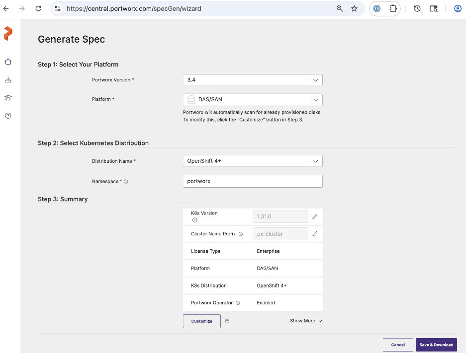
Step 5. Verify information in the Step 3: Summary section and click Save & Download.
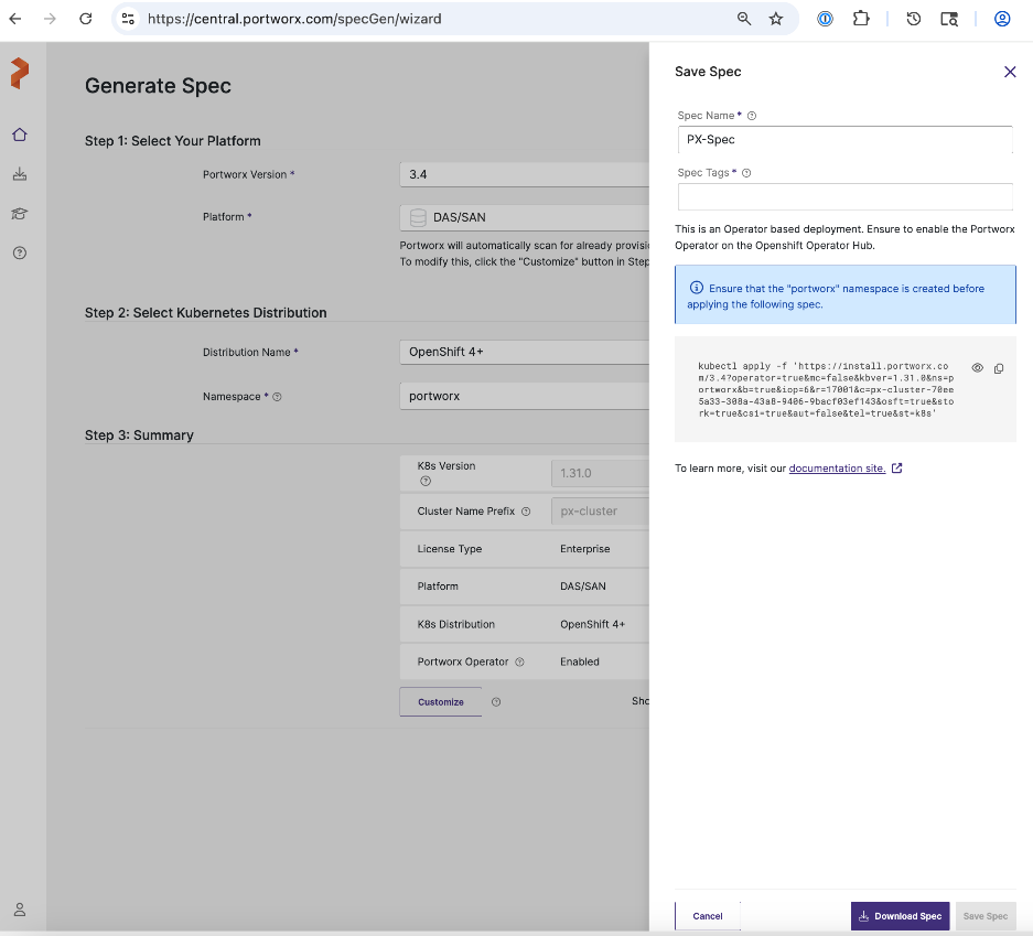
Step 6. Specify a Spec Name. Copy the kubectl command to apply the Portworx cluster spec on the OpenShift cluster later. Click Download Spec and save the file.
Step 7. Copy the spec file to the OpenShift installer workstation. Save the file in the portworx sub-directory under the cluster directory.
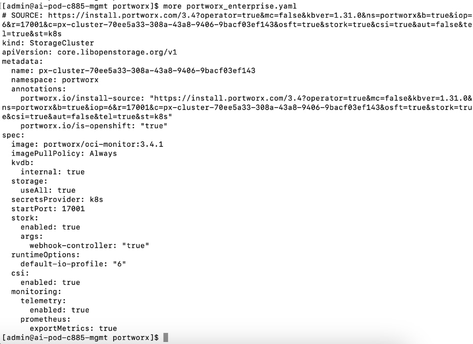
Deploy Portworx Enterprise Operator from Red Hat OpenShift Cluster Console
Procedure 1. Portworx Enterprise Operator from Red Hat OpenShift Cluster Console setup
Step 1. From a browser, log into the OpenShift Cluster Console.
Step 2. From the left navigation menu, go to Operators > OperatorHub. In the search box, enter Portworx.
Step 3. Click the Portworx Enterprise tile when it shows up.
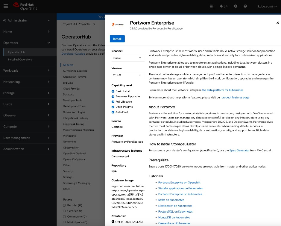
Step 4. Click Install.
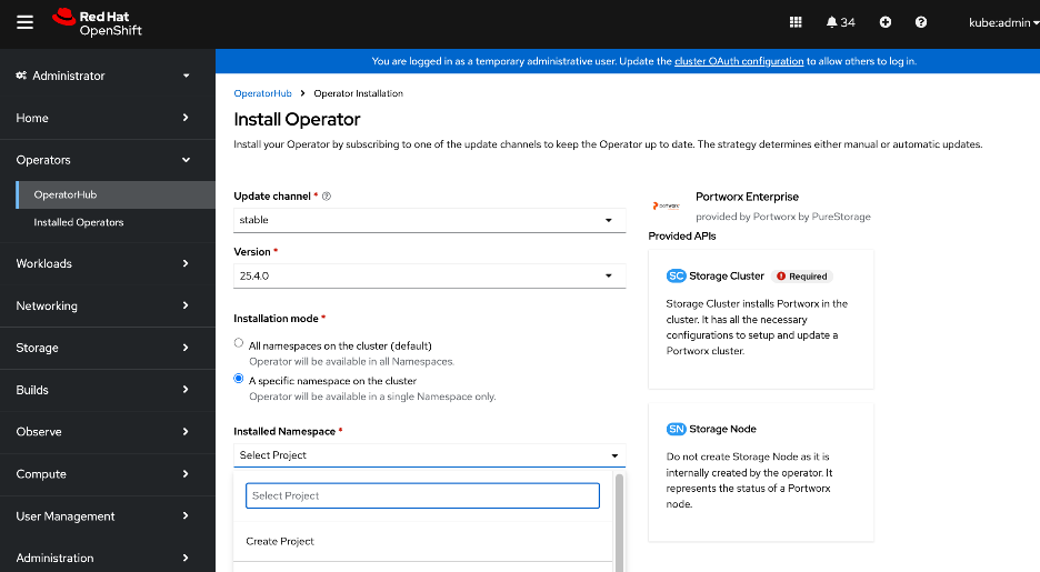
Step 5. For Installation mode, select the radio button for A specific namespace on the cluster.
Step 6. For Installed Namespace, click Create Project and specify a Name (portworx) in the Create Project window.
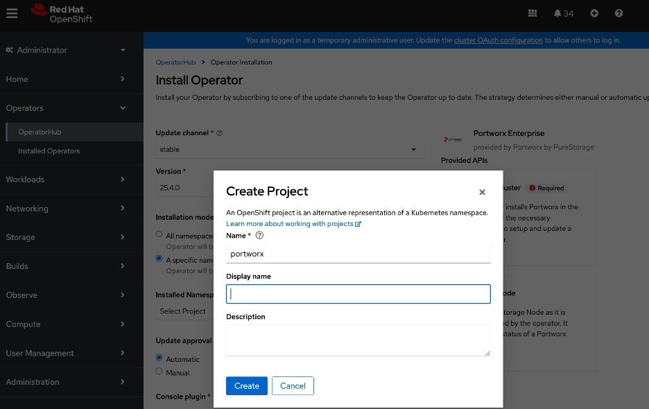
Step 7. Click Create to create a namespace with the specified name.
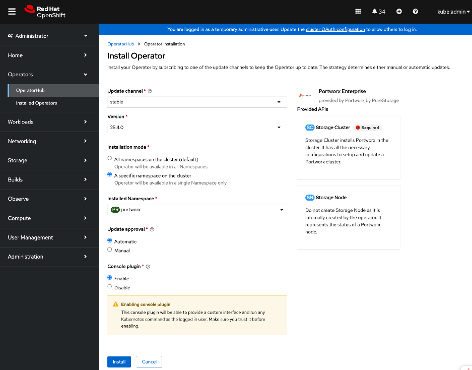
Step 8. Click Install.
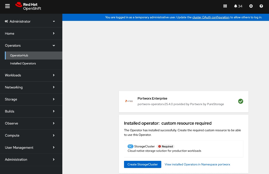
Step 9. Once the operator deploys, click Create StorageCluster.
Step 10. Select YAML view.
Step 11. Copy and paste the specification that was generated in the Generate Portworx Enterprise Specification section into the text editor.
Step 12. Click Create.
Step 13. You can also deploy the previously saved storage cluster specification via CLI from the OpenShift Intaller machine as shown below:

Step 14. The system deploys Portworx, and displays the Portworx instance in the Storage Cluster tab of the Installed Operators page.
Step 15. Scroll down to the bottom of the Details tab. Verify that the install completed successfully.
Step 16. For more information on deploying Portworx Operator on Red Hat OpenShift, see:
Verify that Portworx cluster is up and running in OpenShift
Procedure 1. Portworx cluster running in OpenShift verification
Step 1. From a browser, log into the OpenShift cluster console.
Step 2. From the left navigation menu, go to Portworx > cluster. Monitor the status of the cluster. Scroll down and verify that all nodes are listed as being part of the portworx cluster. The local drive information on each of the nodes are displayed but that can be ignored as we are not using local storage.
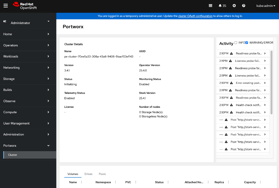
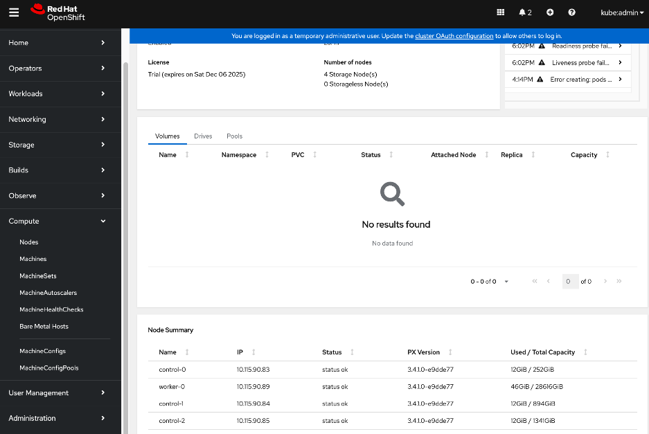
Step 3. From OpenShift installer machine, verify the status of the cluser. It will take a few minutes for all the PODs to come up and be in a READY state.
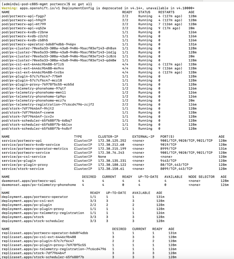
Step 4. SSH into each node as user core. Verify portworx status is operational on each node and that you have a valid license. Ignore all information regarding local drives and local storage since we’re using Everpure FlashBlade in this setup.
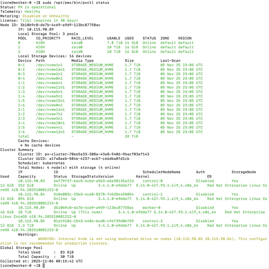
You can also execute the same command OpenShift Installer workstation:
oc exec <pod-name> -n portworx -- /opt/pwx/bin/pxctl status
Set up Portworx for NFS over TCP Access to Storage
Storage Class configuration in Kubernetes specifies how persistent storage should be created and managed in Kubernetes. It specifies the back-end type (pure_file for FlashBlade), NFS export rules that control access to the mounted filesystem, and mountOptions. Everpure FlashBlade is provisioned as Direct Access filesystem. The rules for accessing NFS storage on FlashBlade is defined in accessModes in the Persistent Volume Claim (PVC) configuration. This rule is also set in the storage class for the following access modes as listed below:
● *(rw): ReadWriteOnce, ReadWriteMany, and ReadWriteOncePod. This setting allows clients to perform both read and write operations on the storage.
● *(ro): ReadOnlyMany. This setting ensures that the storage can only be accessed in read-only mode, preventing modifications to the data.
Also, no_root_squash is recommended in the storage class export rules to prevent any permission issues. FlashBlade exports use root_squash by default. If your pod sets an fsGroup, this may result in permission errors (e.g., permission denied, lchown failed). To prevent this, set the parameters.pure_export_rules field to *(rw,no_root_squash) in the StorageClass object.
The procedures in this section:
● Create Storage Class for NFS over TCP to Everpure FlashBlade
● Create a Persistent Volume Claim to verify setup
Assumptions and Prerequisites
● Everpure FlashBlade’s Management endpoint IP is reachable from all OpenShift nodes on the in-band management network.
● Everpure FlashBlade’s NFS Storage Data endpoint IP is reachable from all OpenShift nodes on the storage data network.
● Portworx by Everpure operator has been deployed and setup.
Setup Information
This information is provided in line with the deployment steps.
Deployment Steps
To provision Portworx to use NFS over TCP to access storage on Everpure FlashBlade, complete the procedures below using the setup information provided in this section.
Create Storage Class for NFS over TCP to Everpure FlashBlade
Procedure 1. Set up storage class for NFS over TCP to Everpure FlashBlade
Step 1. SSH into the OpenShift installer workstation.
Step 2. Go to the portworx sub-directory in the OpenShift cluster directory.
Step 3. Create storage class configuration (.yaml file).
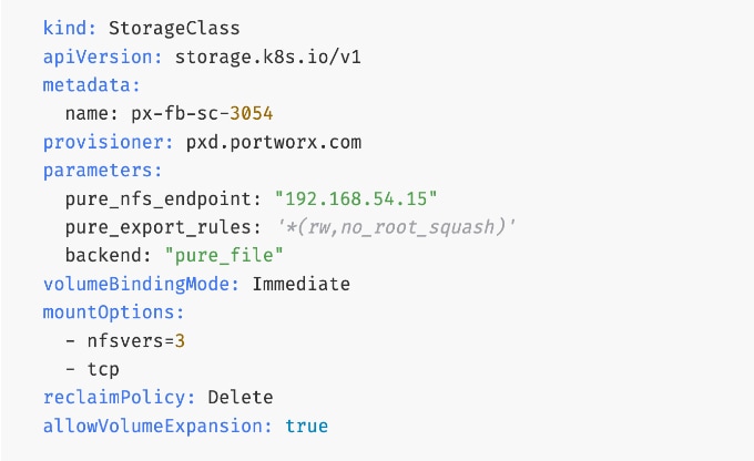
Note: Optional: You can nconnect=16 in the mountOptions section of the above YAML file to support multiple parallel connections and ensure that users can fully saturate the available bandwidth on the frontend links.
Step 4. Verify the corresponding FlashBlade NFS export rules settings as shown below:
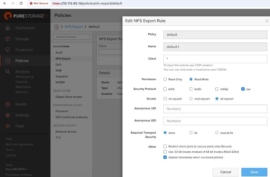
Step 5. Create and deploy the storage class to the OpenShift cluster:
oc apply -f <storage_class_config.yaml>
Step 6. (Optional) Make the provisioned storage class the default class:
oc patch storageclass <storage_class_name.yaml> -p '{"metadata": {"annotations": {"storageclass.kubernetes.io/is-default-class": "true"}}}'
Step 7. The final deployed storage class configuration should be as follows:
kind: StorageClass
apiVersion: storage.k8s.io/v1
metadata:
name: px-fb-sc-3054
annotations:
storageclass.kubernetes.io/is-default-class: 'true'
provisioner: pxd.portworx.com
parameters:
pure_nfs_endpoint: "192.168.54.15"
pure_export_rules: '*(rw,no_root_squash)'
backend: "pure_file"
volumeBindingMode: Immediate
mountOptions:
- nfsvers=3
- tcp
reclaimPolicy: Delete
allowVolumeExpansion: true
Step 8. Use oc get storageclasses.storage.k8s.io to view the storage classes, including the default storage classes.
For more information, see:
Create a Persistent Volume Claim to verify setup
Procedure 1. Persistent volume claim setup verification
Step 1. From the OpenShift Installer machine, create the following PVC configuration (.yaml) file:
kind: PersistentVolumeClaim
apiVersion: v1
metadata:
name: pure-check-pvc-fb-rwm
spec:
accessModes:
- ReadWriteMany
resources:
requests:
storage: 10Gi
storageClassName: px-fb-sc-3054
Step 2. Create and deploy the PVC to the OpenShift cluster:
oc apply -f <pvc_name.yaml>
Step 3. Verify the status of the PVC via CLI or from OpenShift cluster console:
oc get pvc
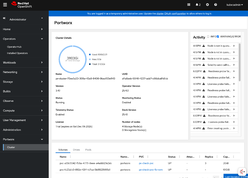
For more information, see: https://docs.portworx.com/portworx-enterprise/platform/provision-storage/create-pvcs/pure-flashblade
This section details the procedures for deploying and setting up the NVIDIA GPU Operator. The operator will automate the life-cycle management of all software components on the NVIDIA GPUs so they can be used by workloads running on the OpenShift cluster. Some of the components deployed by the operator include:
● NVIDIA Drivers: To enable CUDA execution on the GPUs.
● NVIDIA Container Toolkit: To allow containers to interact with the GPU.
● Kubernetes Device Plugin: To expose the GPUs to the Kubernetes scheduler.
● DCGM Exporter: For monitoring GPU metrics and health.
For more information on NVIDIA GPU Operator, see:
https://docs.nvidia.com/datacenter/cloud-native/gpu-operator/latest/overview.html
The procedures in this section will:
● Deploy Red Hat Node Feature Discovery Operator
● Deploy NVIDA GPU Operator
● Enable Data Center GPU Monitoring (DCGM) dashboard in OpenShift cluster console
● Set up taints on worker nodes and tolerations on workloads (or Pods). For more information, see the Red Hat documentation: https://docs.redhat.com/en/documentation/openshift_container_platform/4.18/html/nodes/controlling-pod-placement-onto-nodes-scheduling#nodes-scheduler-taints-tolerations-about_nodes-scheduler-taints-tolerationshttps://docs.redhat.com/en/documentation/openshift_container_platform/4.18/html/nodes/controlling-pod-placement-onto-nodes-scheduling#nodes-scheduler-taints-tolerations-about_nodes-scheduler-taints-tolerations
Note: This CVD uses Red Hat’s Node Feature Discovery Operator instead of the NVIDIA GPU Feature Discovery (GFD) for node labeling.
Assumptions and Prerequisites
● OpenShift cluster is deployed and operational.
Setup Information
This information is provided in line with the deployment steps.
Deployment Steps
Prerequisite: Deploy Red Hat Node Feature Discovery Operator
To deploy NVIDIA's GPU Operator in Red Hat OpenShift, the Red Hat Node Feature Discovery (NFD) Operator must be deployed first. Complete the following steps to deploy this operator.
Note: This CVD uses Red Hat NFS instead of NVIDIA’s GPU Feature Discovery Operator for node labeling.
Procedure 1. Deploy Red Hat node feature discovery operator
Step 1. From a browser, log into the OpenShift Cluster Console.
Step 2. From the left navigation menu, go to Operators > Operator Hub.
Step 3. In the search box, enter Node Feature Discovery.
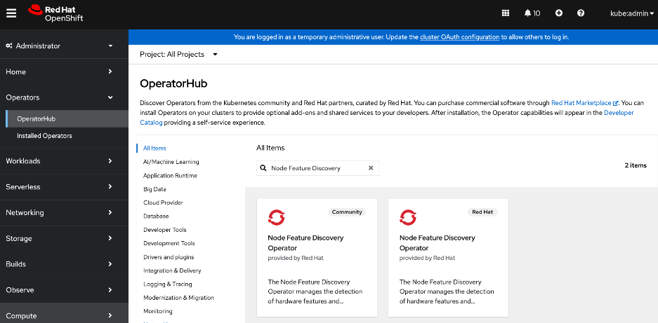
Step 4. Choose Node Feature Discovery Operator tile provided by Red Hat. Click the second Node Feature Discovery Operator tile (not the Community) provided by Red Hat when it shows up.
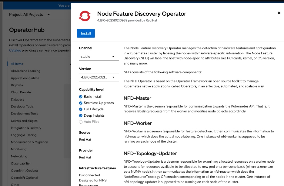
Step 5. In the Node Feature Discovery Operator window, click Install.
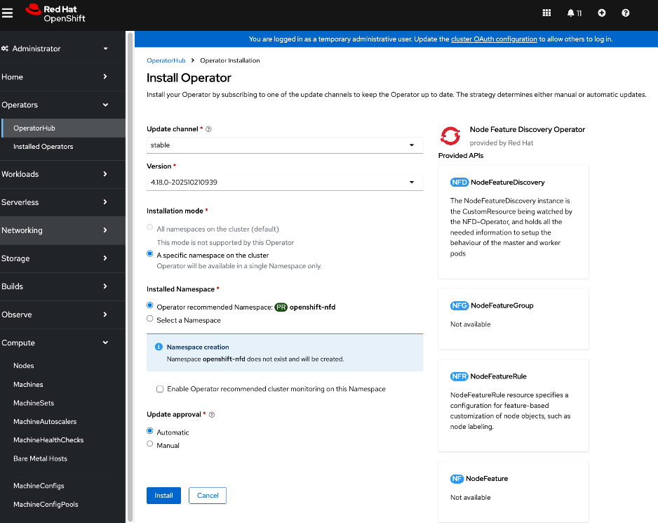
Step 6. Keep the default settings (A specific namespace on the cluster). The operator will be deployed in the openshift-nfd namespace. Click Install. This will take several minutes on large servers like Cisco UCS C885A with 8 GPUs, 8+ NICs, and so on.
Note: In OpenShift 4.18 release used in validation, an additional DNS entry for api-int.ocp-c885.aipod.local had to be added for this operator to deploy successfully.
Step 7. When the Node Feature Discovery Operator installation completes, click View Operator.
Step 8. From the top menu bar, go to the NodeFeatureDiscovery tab.
Step 9. Click Create NodeFeatureDiscovery.
Step 10. Keep the default settings and click Create.
Step 11. Verify that the nfd-instance has a status of: Available, Upgradeable
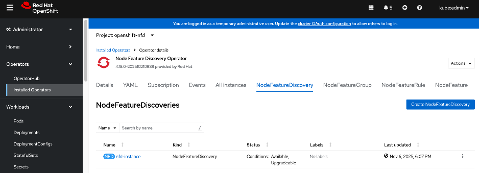
Step 12. To confirm that NFD labelled the worker nodes with NVIDIA GPUs correctly, go to Compute > Nodes and a choose a worker node with GPU.
Step 13. Go to the Details tab and verify that the worker node has the label for NVIDIA GPUs (pci-10de).
feature.node.kubernetes.io/pci-10de.present=true
Step 14. You can also use the following CLI commands from OpenShift Installer workstation to verify this across all nodes:
oc get nodes -l feature.node.kubernetes.io/pci-10de.present
oc get node -o json | jq '.items[0].metadata.labels | with_entries(select(.key | startswith("feature.node.kubernetes.io")))'
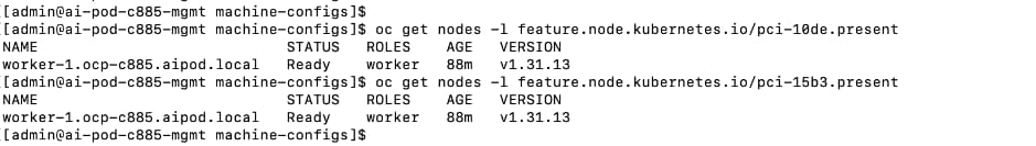
Deploy the NVIDIA GPU Operator on Red Hat OpenShift
Procedure 1. NVIDIA GPU operator on Red Hat OpenShift deployment
Step 1. From a browser, log into OpenShift Cluster Console.
Step 2. From the left navigation menu, go to Operators > Operator Hub.
Step 3. In the search box, enter GPU Operator.
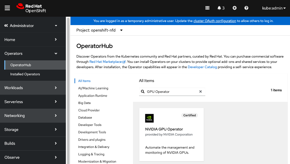
Step 4. Click the (Certified) NVIDIA GPU Operator tile.
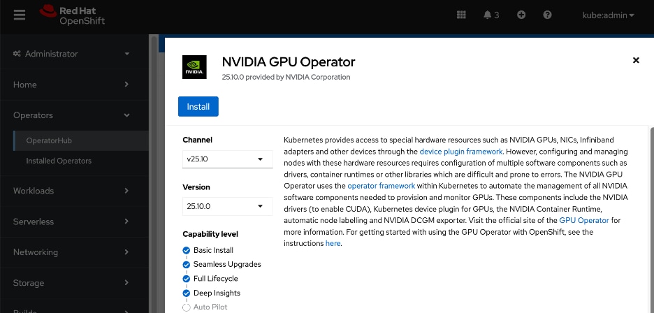
Step 5. Click Install.
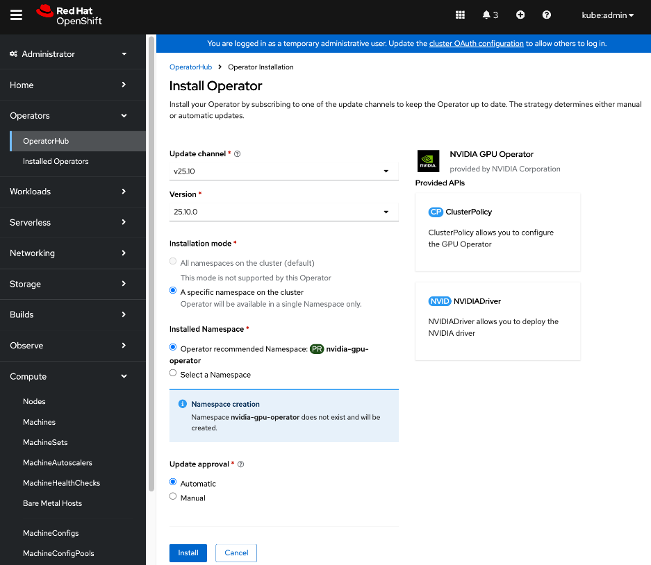
Step 6. Keep the default settings (A specific namespace on the cluster: nvidia-gpu-operator) and click Install.
Step 7. When the installation completes, click View Operator.
Step 8. Go to the ClusterPolicy tab, then click Create ClusterPolicy. The platform assigns the default name of gpu-cluster-policy.
Step 9. Keep the default settings and click Create.
Step 10. Wait for the gpu-cluster-policy status to become Ready.
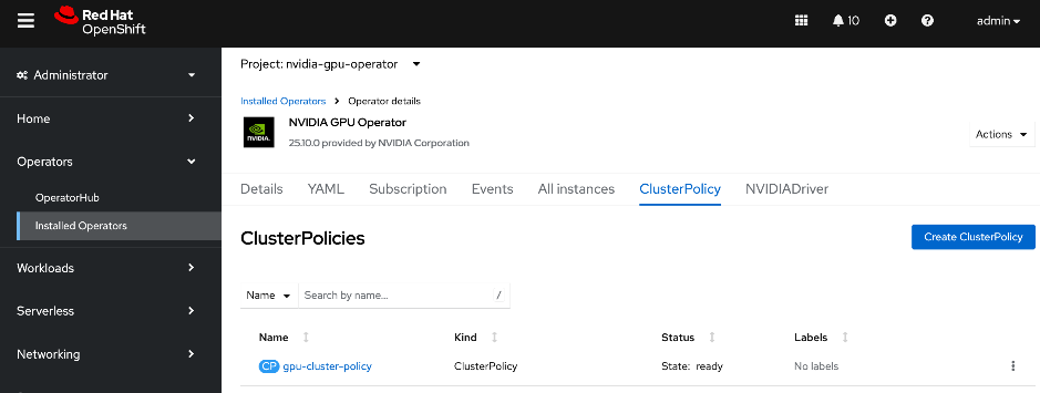
Step 11. Log into the OpenShift Installer machine and check the status of the servers with GPUs by running the following:
oc project nvidia-gpu-operator
oc get pods
Step 12. Connect to one of the nvidia-driver-daemonset containers and view the GPU status:
oc exec -it <name of nvidia driver daemonset> –- nvidia-smi (OR)
oc exec -it <name of nvidia driver daemonset> –- bash
nvidia-smi
Enable NVIDIA GPU DCGM Monitoring on Red Hat OpenShift
Procedure 1. Set up NVIDIA GPU DCGM monitoring on Red Hat OpenShift
Step 1. From a browser, log into OpenShift cluster console.
Step 2. From the left navigation menu, go to Observe > Dashboards.
Step 3. In the Dashboard section, select NVIDIA DCGM Exporter Dashboard from the drop-down list.
Step 4. You can now use the OpenShift console to monitor the NVIDIA GPUs.
For more information, see: https://docs.nvidia.com/datacenter/cloud-native/openshift/latest/enable-gpu-monitoring-dashboard.html
Setup Taints and Tolerations
Taints and Tolerations are used to ensure that AI/ML workloads requiring GPU resources are deployed only on nodes equipped with GPUs. They enable OpenShift to control the placement (or not) of workloads (or Pods) on worker nodes.
Taints prevent workloads/pods from being scheduled on a node unless it has a matching toleration. Tolerations allow workloads/pods to be scheduled on nodes that have a matching taint. One or more taints can be applied to a node. Taints are applied to nodes while tolerations are appled to workloads/pods. In an AI cluster, it is critical to have the NoSchedule taint on the GPU-dense worker nodes to prevent OpenShift from scheduling non-AI workloads on these nodes that can result in resource contention and degrade performance for high-priority training jobs.
Unlike Node affinity rules that place workloads (or Pods) on a preferred set of nodes, taints have the opposite effect of keeping workloads (or Pods) from being scheduled on certain nodes.
For more information, see: https://docs.redhat.com/en/documentation/openshift_container_platform/4.18/html/nodes/controlling-pod-placement-onto-nodes-scheduling#nodes-scheduler-taints-tolerations-about_nodes-scheduler-taints-tolerations.
Procedure 1. Configure taints on OpenShift worker nodes with GPUs
Step 1. From a browser, log into OpenShift cluster console.
Step 2. From the left navigation menu, go to Compute > Nodes.
Step 3. Choose a worker node with GPU from the list.
Step 4. Go to the YAML tab.
Step 5. Click Actions and choose Edit node from the drop-down list.
Step 6. Add the following to the spec: section of the YAML configuration:
taints:
- key: nvidia.com/gpu
effect: NoSchedule
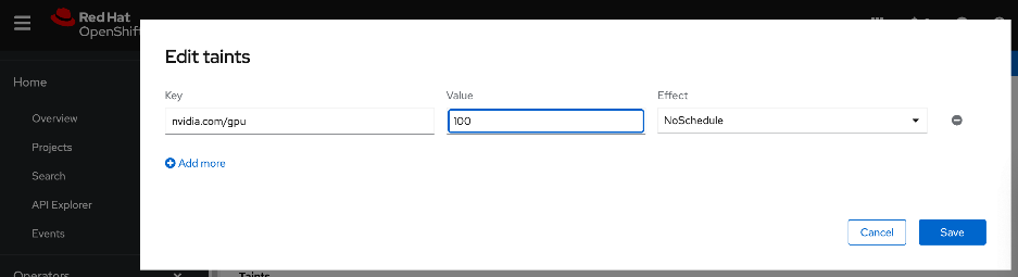
Step 7. Click Save.
Procedure 2. Configure tolerations on Pods allowing workloads requiring GPUs deployed on nodes with matching taints
Step 1. Go to Workloads > Pods.
Step 2. For Project, choose nvidia-gpu-operator from the drop-down list.
Step 3. Search and find the pod name that starts with: nvidia-driver-daemonset that is running on the worker node where you deployed the taint.
Step 4. From the Details tab, click the pencil icon add the following if it doesn’t already exist:
tolerations:
- key: nvidia/gpu
operator: Exists
effect: NoSchedule
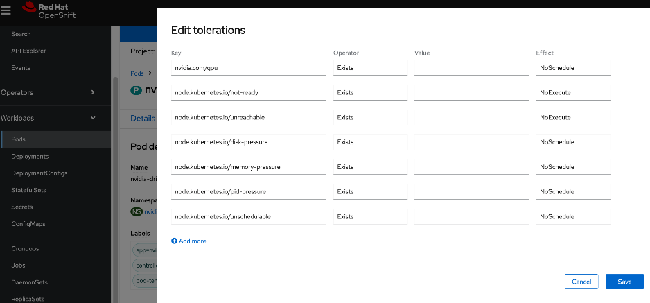
Step 5. Click Save.
Validate – Deploy GPU workload
This is a placeholder step to verify that GPUs can be allocated to workloads and functioning as expected. For this CVD, this was done using one of the relevant validation methods detailed in the Solution Validation > Validation Summary section.
Deploy GPUDirect RDMA on Backend Fabric
This section details the procedures for deploying and setting up GPUDirect RDMA for GPU-to-GPU communication across the backend fabric. This requires both NVIDIA network and GPU Operators to be provisioned. The operators will automate the life-cycle management of all software components on NVIDIA NICs and GPUs for use by AI workloads running on the OpenShift cluster.
The procedures in this section:
● Collect MAC Addresses for all E-W and N-S NICs and interface names for the Cisco UCS C885As
● Create and apply unique node label to Cisco UCS C885A nodes
● Create a new machine config pool with only Cisco UCS C885 GPU nodes
● Create Persistent Interface Naming for all NVIDIA NICs.
● Verify that NVIDIA network devices are present and labelled
● Create password for core user to access node
● Blacklist Kernel Modules
● Set MTU to 9000 on NVIDIA backend NICs
● Deploy NVIDIA Network Operator from Red Hat Cluster Console
● Create NIC Cluster Policy for NVIDIA Network Operator
● Set MTU to 9000 on NVIDIA backend NICs
● Create MAC VLAN Network to provision backend interfaces
● Deploy ARP and RP policies on UCS GPU Nodes
● Create GPU Cluster Policy for NVIDIA GPU Operator
Assumptions and Prerequisites
● Any BlueField-3 NICs in the system should be converted to NIC Mode. Default is DPU mode. This can be configured through the BIOS.
● Cisco UCS C885A nodes are claimed in Intersight account.
● Red Hat’s Node Feature Discovery Operator deployed. Confirm that all NVIDIA GPUs and NICs have been detected and labelled correctly. See the Deploy NVIDIA GPU OperatorDeploy NVIDIA GPU Operator section for more information.
● Kubernetes NMState Operator deployed
● Intel OCP NIC on each server has been setup for SSH access from a directly connected workstation (jump host). In an OpenShift deployment, the workstation must be on the same subnet (not routed) as the Intel NIC. This provides backup access to the nodes in the event of a networking issue.
Setup Information
This information is provided in line with the deployment steps.
Deployment Steps
To deploy GPUDirect RDMA on UCS C885A nodes, complete the procedures in this section using the setup information provided above.
Collect MAC address for all NVIDIA NICs on Cisco UCS C885A nodes from Cisco Intersight
Procedure 1. Collect MAX address for NVIDIA NICs from Cisco Intersight
Step 1. Use a browser to navigate to intersight.com and log into the account used to manage the UCS servers in the cluster.
Step 2. From the left navigation menu, go to Operate > Servers.
Step 3. Select the first UCS C885A node in the cluster and select the Inventory tab.
Step 4. Expand the Network Adapters section and for each frontend and backend adapter, note the MAC Address listed in the DCE Interfaces section of the page.
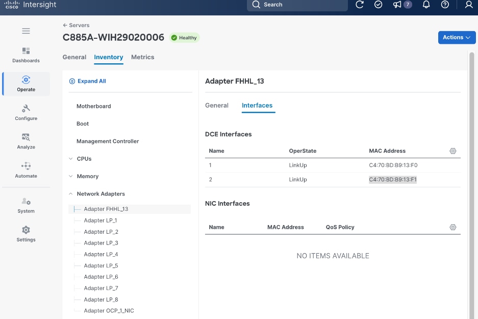
Step 5. Repeat this procedure for remaining nodes in the cluster.
Put Portworx in maintenance mode
Procedure 1. Set up Portworx in maintenance mode
Step 1. SSH into the OpenShift installer workstation.
Step 2. Go to the OpenShift cluster directory.
Step 3. Delete or migrate applications using Portworx to non-UCS C885A nodes in the cluster:
oc adm cordon <node>
oc delete pod <pod-name>
Step 4. Enter maintenance mode:
pxctl service maintenance --enter
Step 5. Exit maintenance mode:
pxctl service maintenance --exit
Step 6. Put node back into use:
oc adm uncordon <node>
Create and apply a unique node label to Cisco UCS C885A GPU Nodes
Procedure 1. Configure a unique node label to Cisco UCS C885A GPU nodes
Step 1. SSH and log into the OpenShift Installer machine used to manage the OpenShift cluster.
Step 2. Go to the cluster directory.
Step 3. Run the following commands to label the first UCS C885A node in the cluster:
$ oc get nodes
$ oc label node <node_name> node-role.kubernetes.io/<label-key>=<label-value>
$ oc get node worker-0 --show-labels
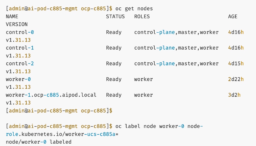
Step 4. Repeat this procedure for all Cisco UCS C885A nodes in the cluster.
Create a new machine config pool with only Cisco UCS C885A GPU worker nodes
Procedure 1. Set up a new machine config pool with Cisco UCS C885A GPU worker nodes
Step 1. SSH and log into the OpenShift Installer machine used to manage the OpenShift cluster.
Step 2. Go to the cluster directory.
Step 3. In the machine-configs sub-directory (created earlier), create a new machineconfigpool for C885A nodes using the new label as shown below:
apiVersion: machineconfiguration.openshift.io/v1
kind: MachineConfigPool
metadata:
name: worker-ucs-c885a
spec:
machineConfigSelector:
matchExpressions:
- {key: machineconfiguration.openshift.io/role, operator: In, values: [worker,worker-ucs-c885a]}
nodeSelector:
matchLabels:
node-role.kubernetes.io/worker-ucs-c885a: ""
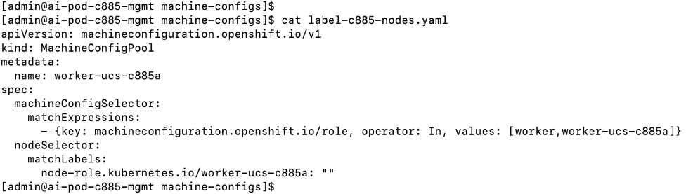
Step 4. Deploy (oc create or oc apply) the above configuration to the OpenShift cluster.
Step 5. Monitor the progress as shown. Note that this will take a few minutes. You can also launch vKVM from Cisco Intersight and monitor progress from the server console.

Create persistent interface naming for all NVIDIA NICs
In some scenarios, the device names for the NVIDIA NICs on the system do not persist on reboot. You can avoid this making device names persistent using Machine Configuration files.
Procedure 1. Set up persistent interface naming for all NVIDIA NICs
Step 1. SSH and log into the OpenShift Installer machine used to manage the OpenShift cluster.
Step 2. Go to the cluster directory.
Step 3. Run the following command:
[core@worker-0 ~]$ ifconfig | grep -A 1 '^ens'
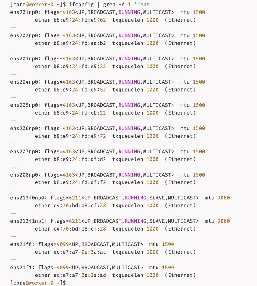
Step 4. In the machine-configs sub-directory created earlier, save the mac addresses and interface names for the eight (1-port) backend NICs and 1 (2-port) frontend NIC.
Step 5. For bonded interfaces, collect the mac address of the second interface as shown below. The frontend NIC is in a bond and will have identical mac address due to the bond.
ip address show <interface name of second interface in the bond>
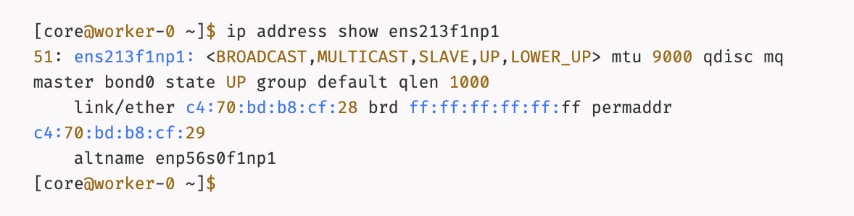
Step 6. In the machine-configs sub-directory, create a copy of the file. Edit the new file (for example, 70-persistent-net.rules) with the collected information formatted as shown below:
SUBSYSTEM=="net",ACTION=="add",ATTR{address}=="b8:e9:24:fd:e9:62",ATTR{type}=="1",NAME="ens201np0"
SUBSYSTEM=="net",ACTION=="add",ATTR{address}=="b8:e9:24:fd:ea:b2",ATTR{type}=="1",NAME="ens202np0"
.
.
.
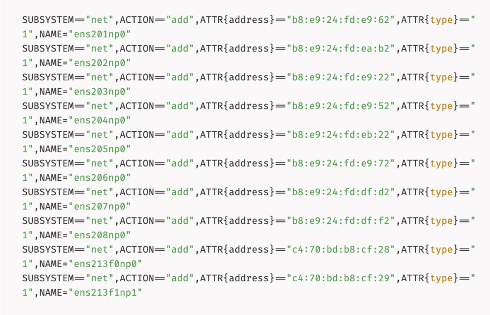
Step 7. Repeat steps 1 – 6 for each node. Add the formatted mac and interface names to the same file.
Step 8. Convert that file into a base64 string without line breaks and set the output to the variable PERSIST.
PERSIST=`cat 70-persistent-net.rules| base64 -w 0`
echo $PERSIST
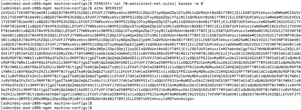
Step 9. Create a machine configuration file (for example, 99-machine-config-udev-network.yaml) and set the base64 encoding in the custom resource file as shown below:
cat <<EOF > 99-machine-config-udev-network.yaml
apiVersion: machineconfiguration.openshift.io/v1
kind: MachineConfig
metadata:
labels:
machineconfiguration.openshift.io/role: worker
name: 99-machine-config-udev-network
spec:
config:
ignition:
version: 3.2.0
storage:
files:
- contents:
source: data:text/plain;base64,$PERSIST
filesystem: root
mode: 420
path: /etc/udev/rules.d/70-persistent-net.rules
EOF

Step 10. Apply the configs using the following commands:
oc apply -f 99-machine-config-udev-network.yaml
Step 11. Monitor the status of the machine config changes. The status of the UPDATING column should be True. It will take a few minutes.
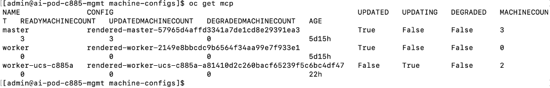
Verify that NVIDIA network devices are present and labelled
This is a prerequisite for deploying the NVIDIA Network Operator. If the NVIDIA NICs are present, the previously deployed Node Feature Discovery Operator (NFD) would have labelled the node with the relevant PCIe and other information. To confirm this, follow the procedures below.
Procedure 1. NVIDIA network devices verification
Step 1. SSH and log into the OpenShift Installer machine used to manage the OpenShift cluster.
Step 2. Run the following command. There should be a pci-15b3.present=true line for every node in the cluster as shown below:
oc describe node | grep -E 'Roles|pci' | grep pci-15b3
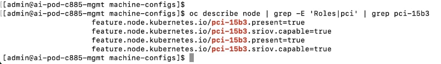
Create password for core user to access node
By default, Red Hat Enterprise Linux CoreOS (RHCOS) creates a user core on the nodes in your cluster that can be accessed without a password if SSH keys were provided at install time. However, if the node is not accessible via ssh core@<node_ip> or oc debug node/<node_hostname>, this procedure allows you to setup a password for user ‘core’ that will allow you to login to the node via vKVM. You can also use this password for SSH via Intel OCP NICs – you will need to copy the SSH edcsa/rsa keys to the jump host used to access the node.
Procedure 1. Set up password for core user for node access
Step 1. SSH and log into the OpenShift Installer machine used to manage the OpenShift cluster.
Step 2. Go to the cluster directory. Go to the previously created machine-configs sub-directory.
Step 3. Run the following command to create a hashed password:
mkpasswd -m SHA-512 <password>
Step 4. Create a machine config YAML file (for example, core-hash-password.yaml) with the following configuration. Specify the hashed password above as the password for the variable passwordHash:
apiVersion: machineconfiguration.openshift.io/v1
kind: MachineConfig
metadata:
labels:
machineconfiguration.openshift.io/role: worker
name: set-core-user-password
spec:
config:
ignition:
version: 3.4.0
passwd:
users:
- name: core
passwordHash: <password>
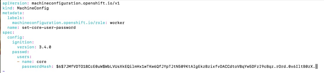
Step 5. Save the file in the machine-configs sub-directory.
Step 6. Apply the YAML config to OpenShift cluster:
oc apply -f <file-name>.yaml
![]()
Step 7. The nodes do not reboot. However, the machine config pools should get updated. Confirm that it does. It should transition from Updating > True to Updated > True after a few minutes.
[admin@ai-pod-c885-mgmt machine-configs]$ oc get mcp
NAME CONFIG UPDATED UPDATING DEGRADED MACHINECOUNT READYMACHINECOUNT UPDATEDMACHINECOUNT DEGRADEDMACHINECOUNT AGE
master rendered-master-57965d4affd3341a7de1cd8e29391ea3 True False False 3 3 3 0 4d17h
worker rendered-worker-809a037ecb8082fee4d853c13b1da6d7 True False False 0 0 0 0 4d17h
worker-ucs-c885a rendered-worker-ucs-c885a-b0514299f3892356170bb96a7ac087a2 False True False 2 1 1 0 69m
[admin@ai-pod-c885-mgmt machine-configs]$

Step 8. Verify that the password is in place using the following commands. Also confirm that it works by logging into the node from vKVM console launched from Cisco Intersight or by initiating an SSH from jump host to the node via Intel OCP NIC.
oc debug node/<node_name>
chroot /host
cat /etc/shadow
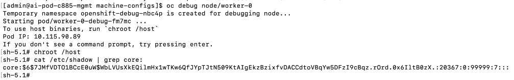
Blacklist Kernel Modules
When the NIC cluster policy for the NVIDIA Network Operator is deployed, the NVIDIA DOCA-OFED drivers are loaded on all NVIDIA ConnectX and BlueField-3 adapters on the nodes in the OpenShift cluster. However, certain kernel modules (e.g., irdma) can prevent the NVIDIA network drivers from loading properly. To prevent this, these modules should be blacklisted so they are not loaded during the server boot process. This is done using OpenShift MachineConfigs and requires a reboot of the node.
If the OpenShift cluster has a mix of worker nodes, these MachineConfigs should be applied specifically to the Cisco UCS C885A M8 nodes by using the appropriate role (for example, worker-ucs-c885a).
Note: While the example below shows blacklisting of both rpcrdma and irdma modules, blacklist rpcrdma only if it is required for your specific environment, as it may not be necessary in all deployments.
Procedure 1. Set up blacklist kernel module
Step 1. SSH and log into the OpenShift Installer machine used to manage the OpenShift cluster.
Step 2. Go to the cluster directory. Go to previously created machine-configs sub-directory.
Step 3. Run the following command to create a machine config YAML file (for example, 99-machine-config-blacklist-irdma.yaml):
cat <<EOF > 99-machine-config-blacklist-irdma.yaml
apiVersion: machineconfiguration.openshift.io/v1
kind: MachineConfig
metadata:
labels:
machineconfiguration.openshift.io/role: worker-ucs-c885a
name: 99-worker-blacklist-irdma
spec:
kernelArguments:
- "module_blacklist=rpcrdma,irdma"
EOF
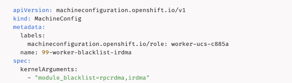
Step 4. Apply the machine config YAML file to the OpenShift cluster:
oc apply -f 99-machine-config-blacklist-irdma.yaml

Step 5. Verify that the Machine Config Pool is getting updated with the new configuration. You can monitor progress using the following command:
oc get mcp

Step 6. You can also monitor progress from OpenShift Cluster console as shown or by launching a vKVM console to the worker nodes from Cisco Intersight.

Step 7. Once the status via CLI (output of oc get mcp) transitions to UPDATING: False and UPDATED: True or Update Status transitions from Updating to Up to date in the Openshift cluster console, you can verify that the kernel modules have been removed using the following commands:
oc debug node/<node_name>
chroot /host
lsmod|grep irdma
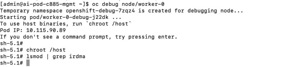
Set MTU to 9000 on NVIDIA Backend NICs
The NVIDIA NICs connecting the Cisco UCS C885A nodes to the backend fabric defaults to an MTU of 1500. To change the MTU to 9000, complete the following procedures.
Procedure 1. Set up MTU to 9000 on NVIDIA backend NICs
Step 1. SSH and log into the OpenShift Installer machine used to manage the OpenShift cluster.
Step 2. Navigate to the cluster directory.
Step 3. Create a sub-directory to save the files in and create a NodeNetworkConfigurationPolicy YAML file with the following configuration. This configuration applies to all UCS nodes in the machine config pool: worker-ucs-c885a as shown below.
Note: The ipv4: section under each interface is used to configure the physical interface which is n
apiVersion: nmstate.io/v1
kind: NodeNetworkConfigurationPolicy
metadata:
name: be-nncp-jumbo-worker-0
spec:
# This selector applies the policy to all nodes with the specific worker role.
# This is more scalable than targeting individual hostnames.
nodeSelector:
node-role.kubernetes.io/worker-ucs-c885a: ""
desiredState:
interfaces:
- name: ens201np0
type: ethernet
state: up
mtu: 9000
ipv4:
enabled: true
dhcp: true
- name: ens202np0
type: ethernet
state: up
mtu: 9000
ipv4:
enabled: true
dhcp: true
- name: ens203np0
type: ethernet
state: up
mtu: 9000
ipv4:
enabled: true
dhcp: true
- name: ens204np0
type: ethernet
state: up
mtu: 9000
ipv4:
enabled: true
dhcp: true
- name: ens205np0
type: ethernet
state: up
mtu: 9000
ipv4:
enabled: true
dhcp: true
- name: ens206np0
type: ethernet
state: up
mtu: 9000
ipv4:
enabled: true
dhcp: true
- name: ens207np0
type: ethernet
state: up
mtu: 9000
ipv4:
enabled: true
dhcp: true
- name: ens208np0
type: ethernet
state: up
mtu: 9000
ipv4:
enabled: true
dhcp: true
Disable PCIe Access Control Services
Access Control Services (ACS) is a PCIe I/O virtualization technology that can impact GPUDirect, including GPUDirect RDMA and GPUDirect Storage, by preventing direct communication between devices (GPU<->NIC) on the same PCIe bus. While ACS provides security in virtualized environments, it can degrade performance by redirecting this traffic through the PCIe Root Complex (CPU).
To ensure optimal, direct RDMA communication, NVIDIA recommends disabling ACS as outlined here. This can be done either in BIOS (if supported) or by using a script after the system is operational. In OpenShift environments, the script can be deployed as a MachineConfig; it must first be encoded in base64.
The original script before base64 encoding is provided below:
#!/bin/bash
# must be root to access extended PCI config space
if [ "$EUID" -ne 0 ]; then
echo "ERROR: $0 must be run as root"
exit 1
fi
for BDF in `lspci -d "*:*:*" | awk '{print $1}'`; do
# skip if it doesn't support ACS
setpci -v -s ${BDF} ECAP_ACS+0x6.w > /dev/null 2>&1
if [ $? -ne 0 ]; then
#echo "${BDF} does not support ACS, skipping"
continue
fi
logger "Disabling ACS on `lspci -s ${BDF}`"
setpci -v -s ${BDF} ECAP_ACS+0x6.w=0000
if [ $? -ne 0 ]; then
logger "Error disabling ACS on ${BDF}"
continue
fi
NEW_VAL=`setpci -v -s ${BDF} ECAP_ACS+0x6.w | awk '{print $NF}'`
if [ "${NEW_VAL}" != "0000" ]; then
logger "Failed to disable ACS on ${BDF}"
continue
fi
done
exit 0
Procedure 2. Disable ACS on OpenShift worker nodes
To disable ACS on OpenShift worker nodes using the script (above), complete the following steps:
Step 1. SSH and log into the OpenShift Installer machine used to manage the OpenShift cluster.
Step 2. Navigate to the cluster directory and go to the previously created machine-configs sub-directory.
Step 3. Create a file (for example, disable-acs.sh) with the above script.
Step 4. Convert the file into a base64 string without line breaks using the following command and copy the output to a file.
SOMEVAR=cat <file_name> | base64 -w 0
Step 5. Copy the output.
Step 6. Create a machineconfig file (for example, 99-machine-config-disable-acs.yaml) with the following information. Insert the base64 encoded script or output as a single line in the source: section, prefixed with data:text/plain;charset=utf-8;base64, as shown below:
apiVersion: machineconfiguration.openshift.io/v1
kind: MachineConfig
metadata:
name: 99-machine-config-disable-acs
labels:
machineconfiguration.openshift.io/role: worker
spec:
config:
ignition:
version: 3.2.0
systemd:
units:
- name: 99-machine-config-disable-acs
enabled: true
contents: |
storage:
files:
- filesystem: root
path: /usr/local/bin/disable-acs.sh
contents:
source: data:text/plain;charset=utf-8;base64,$SOMEVAR
verification: {}
mode: 0755
overwrite: true
Step 7. Deploy the YAML file to the OpenShift cluster:
oc apply -f 99-machine-config-disable-acs.yaml
Step 8. Monitor the progress of the machine config update. The noes will reboot after applying changes. You can monitor the progress as follows. The nodes should all be in the Ready state, but will cycle through states, such as Ready,SchedulingDisabled, NotReady or SchedulingDisabled:
oc get nodes --watch
oc get mcp
Step 9. SSH into the nodes and verify that ACS was disabled using the following command. If lines show “SrcValid-”, then ACS is disabled. For more information, see the NCCL documentation.
sudo lspci -vvv | grep ACSCtl
Disable PCIe IOMMU
The PCIe Input/Output Memory Management Unit (IOMMU) provides memory isolation and protection by providing address translations for I/O devices which requires routing through the PCIe root complex (CPU). However, this can have a negative impact for GPUDirect RDMA performance, particularly for GPUDirect Storage. NVIDIA recommends disabling this as outlined in the following two documents:
GPUDirect Storage Best Practices Guide
CUDA Toolkit Documentation v13.1 Update 1: GPUDirect RDMA
IOMMU can be disabled in BIOS or by adding specific kernel boot parameters via an OpenShift MachineConfig. The kernel parameters can be either (iommu=off or amd_iommu=off)
Note: Deployments using GPUDirect RDMA with SR-IOV where IOMMU=PT is required will not see a performance impact per NVIDIA documentation above.
Procedure 1. Disable IOMMU
Step 1. SSH and log into the OpenShift Installer machine used to manage the OpenShift cluster.
Step 2. Navigate to the cluster directory. Navigate to previously created machine-configs sub-directory.
Step 3. Run the following command to create a machine config YAML file (for example, 99-machine-config-blacklist-irdma-iommu.yaml).
cat <<EOF > 99-machine-config-blacklist-irdma-iommu.yaml
apiVersion: machineconfiguration.openshift.io/v1
kind: MachineConfig
metadata:
labels:
machineconfiguration.openshift.io/role: worker-ucs-c885a
name: 99-worker-blacklist-irdma-iommu
spec:
kernelArguments:
- "module_blacklist=rpcrdma,irdma"
- amd_iommu=off
- iommu=off
EOF
Step 4. Apply the machine config YAML file to the OpenShift cluster:
oc apply -f 99-machine-config-blacklist-irdma-iommu.yaml
Step 5. Verify that the Machine Config Pool is getting updated with the new configuration. You can monitor progress using the following command:
oc get mcp
Step 6. You can also monitor progress from OpenShift Cluster console as shown or by launching a vKVM console to the worker nodes from Cisco Intersight.
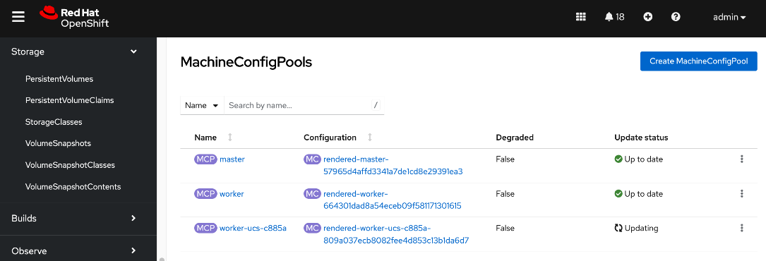
Step 7. Once the status via CLI (output of oc get mcp) transitions to UPDATING: False and UPDATED: True or Update Status transitions from Updating to Up to date in the Openshift cluster console, you can verify that iommu is disabled using the following command.
/usr/local/cuda/gds/tools/gdscheck -p
Remove the previously deployed NVIDIA GPU operator
This is an optional but recommended step to remove the previously deployed NVIDIA GPU operator to avoid conflicts. The NVIDIA GPU Operator will be redeployed later, after the NVIDIA Network Operator is deployed.
Procedure 1. Remove deployed NVIDIA GPU operator
Step 1. From a browser, log into the OpenShift Cluster Console.
Step 2. From the left navigation menu, go to Operators > Installed Operators.
Step 3. Filter on NVIDIA in the Search box.
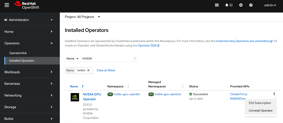
Step 4. Click the ellipses to the right of NVIDIA GPU Operator and select Uninstall Operator in the pop-up.
Deploy NVIDIA Network Operator from Red Hat Cluster Console
The NVIDIA Network Operator lifecycle manages the NVIDIA NICs in the Cisco UCS C885A server and related components such as drivers and device plugins to support inter-node GPUDirect RDMA across backend fabric. The operator also impacts and manages the frontend NICs and is necessary for implementing GPUDirect Storage via the frontend fabric.
This step only deploys the NVIDIA Network Operator. The NIC Cluster Policy for the operator will be deployed later. Deploying the operator will have minimal impact to the system unlike the cluster policy.
Procedure 1. Deploy the NVIDIA Network Operator from the Red Hat Cluster Console
Step 1. From a browser, log into the OpenShift Cluster Console.
Step 2. From the left navigation menu, go to Operators > Operator Hub.
Step 3. In the search box, enter NVIDIA.
Step 4. Click the NVIDIA Network Operator tile.
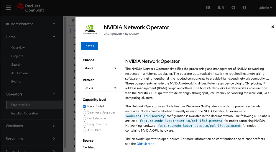
Step 5. Click Install.
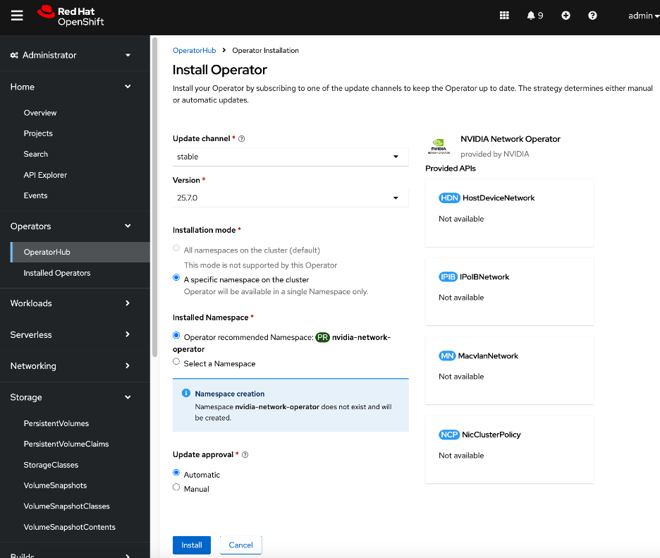
Step 6. Keep the defaults. Click Install.
Step 7. Click View Operator and scroll to the bottom of the page to verify that the operator deployed successfully.
You can also verify that the Network Operator is deployed from CLI using the following steps:
Step 1. SSH and log into the OpenShift Installer machine used to manage the OpenShift cluster.
Step 2. Run the following command. The network operator controller manager should be present on each node with an NVIDIA NIC. In this setup, only Cisco UCS C885A worker nodes have NVIDIA NICs.
oc get pods -n nvidia-network-operator
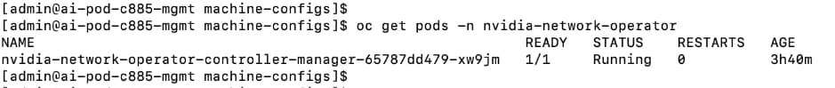
Deploy NVIDIA GPU Operator from Red Hat Cluster Console
The procedure below only deploys the NVIDIA GPU Operator. The GPU cluster policy will be deployed later. Deploying the operator will have minimal impact to the system unlike the cluster policy.
Procedure 1. Deploy NVIDIA GPU Operator from the Red Hat console
Step 1. From a browser, log into OpenShift Cluster Console.
Step 2. From the left navigation menu, go to Operators > Operator Hub.
Step 3. In the search box, enter GPU Operator.
Step 4. Click the (Certified) NVIDIA GPU Operator tile.
Step 5. Keep the default settings. Click Install twice.
Step 6. When the installation completes, click View Operator and verify that the operator deployed successfully.
Create NIC Cluster Policy for NVIDIA Network Operator
This procedure deploys a NIC Cluster Policy for the NVIDIA Network Operator. Before deploying this policy, it is highly recommended that you have the following in place. Verify that you have:
● SSH access via Intel OCP NIC from a directly connect jump host
● Password set up for user: corecore
Note: Deploying this policy will unload the existing in-tree drivers on the NVIDIA NICs and load newer drivers specified through the operator. This will impact the frontend NVIDIA NICs used by the OpenShift cluster. Plan for some outage during this time.
Procedure 1. Create a NIC cluster policy for NVIDIA network operator
Step 1. From a browser, log into the OpenShift Cluster Console.
Step 2. From the left navigation menu, go to Operators > Installed Operators.
Step 3. Click the NVIDIA Network Operator from the list.
Step 4. From the top menu, select the NicClusterPolicy tab.
Step 5. Click Create NicClusterPolicy on the right to create a policy.
Step 6. Modify the default policy as listed below. Specify a name for the policy in the metadata section (for example, nic-cluster-policy.yaml).
● For ofedDriver, add all the env variables listed. The ""name: ENTRYPOINT_DEBUG"" is to enable mofed mofed container logs for debugging purposes and therefore optional. MofedMofed/ofedofed drivers are loaded when the NicClusterPolicyNicClusterPolicy is deployed.
● (Optional) Comment out NVIDIA's IPAM as Red Hat whereabouts with MacvlanNetwork will be used instead to configure the networking to connect to the backend fabric
● For RDMASharedDevicePlugin, the devices in the resource list (ifNames) will depend on which NICs (backend, frontend) NICs you are enabled GPUDirect RDMA for. In this example, the 8 backend NICs are specified as shared NVIDIA GPUDirect RDMA device. To enable the GPUDirect Storage, another resource (rdma_shared_device_b) should be created with the frontend NICs.
● The configuration below is the default policy (for the versions used in CVD validation) with few changes listed above. All others were left as is.
apiVersion: mellanox.com/v1alpha1
kind: NicClusterPolicy
metadata:
name: nic-cluster-policy
spec:
nvIpam:
enableWebhook: false
image: nvidia-k8s-ipam
imagePullSecrets: []
repository: ghcr.io/mellanox
version: v0.2.0
ofedDriver:
env:
- name: CREATE_IFNAMES_UDEV
value: "true"
- name: RESTORE_DRIVER_ON_POD_TERMINATION
value: "true"
- name: UNLOAD_STORAGE_MODULES
value: "true"
- name: ENTRYPOINT_DEBUG
value: "true"
forcePrecompiled: false
image: doca-driver
imagePullSecrets: []
livenessProbe:
initialDelaySeconds: 30
periodSeconds: 30
readinessProbe:
initialDelaySeconds: 10
periodSeconds: 30
repository: nvcr.io/nvidia/mellanox
startupProbe:
initialDelaySeconds: 10
periodSeconds: 20
terminationGracePeriodSeconds: 300
upgradePolicy:
autoUpgrade: true
drain:
deleteEmptyDir: true
enable: true
force: true
podSelector: ""
timeoutSeconds: 300
maxParallelUpgrades: 1
safeLoad: false
version: doca3.1.0-25.07-0.9.7.0-0
rdmaSharedDevicePlugin:
config: |
{
"configList": [
{
"resourceName": "rdma_shared_device_a",
"rdmaHcaMax": 63,
"selectors": {
"ifNames": [
"ens201np0",
"ens202np0",
"ens203np0",
"ens204np0",
"ens205np0",
"ens206np0",
"ens207np0",
"ens208np0"
]
}
}
]
}
image: k8s-rdma-shared-dev-plugin
imagePullSecrets: []
repository: nvcr.io/nvidia/mellanox
version:
Step 7. Click Create.
Step 8. Verify NIC Cluster Policy state is Ready as shown below:
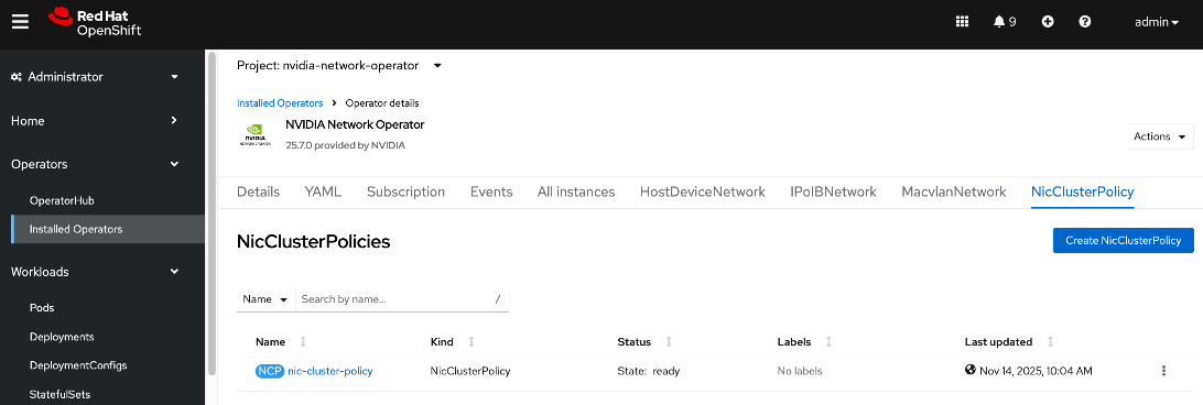
Step 9. SSH and log into the OpenShift Installer machine used to manage the OpenShift cluster.
Step 10. Go to the cluster directory and then to the previously created machine-configs sub-directory.
Step 11. Save the deployed NicClusterPolicy as a YAML file (for example, network-sharedrdma-nic-cluster-policy.yaml). Note that this configuration file will be slightly different from what you’d use to do an initial deployment. This version will have post-deployment info as shown but has the core configuration is still intact.
oc get nicclusterpolicy -o yaml > <file_name>
[admin@ai-pod-c885-mgmt machine-configs]$ oc get nicclusterpolicy -o yaml
apiVersion: v1
items:
- apiVersion: mellanox.com/v1alpha1
kind: NicClusterPolicy
metadata:
creationTimestamp: "2025-11-10T05:57:42Z"
generation: 1
name: nic-cluster-policy
resourceVersion: "6035479"
uid: 2a9cbc64-4b5a-4e98-906a-4a35c0cbb7f9
spec:
nvIpam:
enableWebhook: false
image: nvidia-k8s-ipam
imagePullSecrets: []
repository: ghcr.io/mellanox
version: v0.2.0
ofedDriver:
env:
- name: CREATE_IFNAMES_UDEV
value: "true"
- name: RESTORE_DRIVER_ON_POD_TERMINATION
value: "true"
- name: UNLOAD_STORAGE_MODULES
value: "true"
- name: ENTRYPOINT_DEBUG
value: "true"
forcePrecompiled: false
image: doca-driver
imagePullSecrets: []
livenessProbe:
initialDelaySeconds: 30
periodSeconds: 30
readinessProbe:
initialDelaySeconds: 10
periodSeconds: 30
repository: nvcr.io/nvidia/mellanox
startupProbe:
initialDelaySeconds: 10
periodSeconds: 20
terminationGracePeriodSeconds: 300
upgradePolicy:
autoUpgrade: true
drain:
deleteEmptyDir: true
enable: true
force: true
podSelector: ""
timeoutSeconds: 300
maxParallelUpgrades: 1
safeLoad: false
version: doca3.1.0-25.07-0.9.7.0-0
rdmaSharedDevicePlugin:
config: |
{
"configList": [
{
"resourceName": "rdma_shared_device_a",
"rdmaHcaMax": 63,
"selectors": {
"ifNames": [
"ens201np0",
"ens202np0",
"ens203np0",
"ens204np0",
"ens205np0",
"ens206np0",
"ens207np0",
"ens208np0"
]
}
}
]
}
image: k8s-rdma-shared-dev-plugin
imagePullSecrets: []
repository: nvcr.io/nvidia/mellanox
version: sha256:a87096761d155eeb6f470e042d2d167bb466d57e63b4aba957f57d745e15a9b2
status:
appliedStates:
- name: state-multus-cni
state: ignore
- name: state-container-networking-plugins
state: ignore
- name: state-ipoib-cni
state: ignore
- name: state-whereabouts-cni
state: ignore
- name: state-OFED
state: ready
- name: state-SRIOV-device-plugin
state: ignore
- name: state-RDMA-device-plugin
state: ready
- name: state-ib-kubernetes
state: ignore
- name: state-nv-ipam-cni
state: ready
- name: state-nic-feature-discovery
state: ignore
- name: state-doca-telemetry-service
state: ignore
- name: state-nic-configuration-operator
state: ignore
- name: state-spectrum-x-operator
state: ignore
state: ready
kind: List
metadata:
resourceVersion: ""
[admin@ai-pod-c885-mgmt machine-configs]$
Step 12. Verify the that the mofed pods on each node are up and running:
[admin@ai-pod-c885-mgmt machine-configs]$ oc get pods -n nvidia-network-operator
NAME READY STATUS RESTARTS AGE
mofed-rhcos4.18-7d66f7789d-ds-967jz 2/2 Running 2 20m
mofed-rhcos4.18-7d66f7789d-ds-wxfw8 2/2 Running 0 20m
nv-ipam-controller-65d58f7c47-hssx6 1/1 Running 0 54m
nv-ipam-controller-65d58f7c47-ws9w5 1/1 Running 0 54m
nv-ipam-node-brt9f 1/1 Running 0 54m
nv-ipam-node-dhq5p 1/1 Running 1 54m
nv-ipam-node-k2m6r 1/1 Running 0 54m
nv-ipam-node-mxt2c 1/1 Running 2 54m
nv-ipam-node-r6tl6 1/1 Running 0 54m
nvidia-network-operator-controller-manager-65787dd479-xw9jm 1/1 Running 0 5h37m
rdma-shared-dp-ds-ftn48 1/1 Running 0 19m
rdma-shared-dp-ds-mp58x 1/1 Running 0 3m28s
Step 13. Verify the that all containers in the mofed pods are up and running. Confirm for each node. If mofed pods and containers are up and running, it is likely that the correct mofed drivers got loaded:
oc describe pod <mofed_pod_name>
Note: The mofed drivers, based on mlx5_core kernel drivers, will get loaded on all NVIDIA Mellanox adapters in the system. This includes both backend and frontend NICs.
Step 14. Verify that the correct mofed/ofed drivers are running using the following commands:
oc get pods -n nvidia-network-operator | grep mofed
oc rsh -c mofed-container mofed-rhcos4.<remaining_Pod_name>
ofed_info -s
ibdev2netdev -v
lsmod|grep rdma
lsmod|grep irdma
lsmod|grep rpcrdma
[admin@ai-pod-c885-mgmt ocp-c885]$ oc get pods
NAME READY STATUS RESTARTS AGE
mofed-rhcos4.18-7d66f7789d-ds-btq4b 2/2 Running 0 6m34s
mofed-rhcos4.18-7d66f7789d-ds-f2r8v 2/2 Running 0 6m34s
nvidia-network-operator-controller-manager-845d95fd79-2q6d9 1/1 Running 0 14m
rdma-shared-dp-ds-whsl8 1/1 Running 0 26s
rdma-shared-dp-ds-zjkpq 1/1 Running 0 28s
[admin@ai-pod-c885-mgmt ocp-c885]$
[admin@ai-pod-c885-mgmt ocp-c885]$ oc rsh -c mofed-container mofed-rhcos4.18-7d66f7789d-ds-btq4b
sh-5.1# ofed_info -s
OFED-internal-25.07-0.9.7:
sh-5.1# ibdev2netdev -v
0000:69:00.0 mlx5_0 (MT4129 - 30-100363-01) MCX715105AS-WEAT CX-7 1x400GbE QSFP112 PCIe Gen5 x16 VPI NIC fw 28.43.2026 port 1 (ACTIVE) ==> ens202np0 (Up)
0000:4b:00.0 mlx5_1 (MT4129 - 30-100363-01) MCX715105AS-WEAT CX-7 1x400GbE QSFP112 PCIe Gen5 x16 VPI NIC fw 28.43.2026 port 1 (ACTIVE) ==> ens201np0 (Up)
0000:09:00.0 mlx5_2 (MT4129 - 30-100363-01) MCX715105AS-WEAT CX-7 1x400GbE QSFP112 PCIe Gen5 x16 VPI NIC fw 28.43.2026 port 1 (ACTIVE) ==> ens204np0 (Up)
0000:2b:00.0 mlx5_3 (MT4129 - 30-100363-01) MCX715105AS-WEAT CX-7 1x400GbE QSFP112 PCIe Gen5 x16 VPI NIC fw 28.43.2026 port 1 (ACTIVE) ==> ens203np0 (Up)
0000:f1:00.0 mlx5_4 (MT4129 - 30-100363-01) MCX715105AS-WEAT CX-7 1x400GbE QSFP112 PCIe Gen5 x16 VPI NIC fw 28.43.2026 port 1 (ACTIVE) ==> ens205np0 (Up)
0000:c5:00.0 mlx5_5 (MT4129 - 30-100363-01) MCX715105AS-WEAT CX-7 1x400GbE QSFP112 PCIe Gen5 x16 VPI NIC fw 28.43.2026 port 1 (ACTIVE) ==> ens206np0 (Up)
0000:97:00.0 mlx5_6 (MT4129 - 30-100363-01) MCX715105AS-WEAT CX-7 1x400GbE QSFP112 PCIe Gen5 x16 VPI NIC fw 28.43.2026 port 1 (ACTIVE) ==> ens207np0 (Up)
0000:a4:00.0 mlx5_7 (MT4129 - 30-100363-01) MCX715105AS-WEAT CX-7 1x400GbE QSFP112 PCIe Gen5 x16 VPI NIC fw 28.43.2026 port 1 (ACTIVE) ==> ens208np0 (Up)
0000:38:00.0 mlx5_bond_0 (MT41692 - 900-9D3B6-00SV-AA0) BlueField-3 P-Series DPU 200GbE/NDR200 dual-port QSFP-DD112, PCIe Gen5.0 x16 FHHL, Crypto Disabled, 32GB DDR5, BMC, Tall Bracket fw 32.44.1036 port 1 (ACTIVE) ==> bond0 (Up)
sh-5.1#
Create MAC VLAN Network to provision backend interfaces
Procedure 1. Set up the MAC VLAN network to provision backend interfaces
Step 1. SSH and log into the OpenShift Installer machine used to manage the OpenShift cluster.
Step 2. Go to the cluster directory.
Step 3. Create a sub-directory (for example, mac-vlan-network) to save the configuration files in.
Step 4. Create a MacvlanNetwork YAML file with the following configuration for each interface on the node. The configuration files for the first interface is shown below:
[admin@ai-pod-c885-mgmt ocp-c885]$ cat mac-vlan-network/mac-vlan-network-0.yaml
apiVersion: mellanox.com/v1alpha1
kind: MacvlanNetwork
metadata:
name: be-mac-vlan-network-0
spec:
networkNamespace: default
master: ens201np0
mode: bridge
mtu: 9000
ipam: '{"type": "whereabouts", "range": "192.168.2.0/24" }'
Step 5. Repeat steps 1 – 4 for the remaining 6 backend interfaces on the node. You should have 8 of these files per node. Create and move the files to a node specific directory (for example, worker-0).
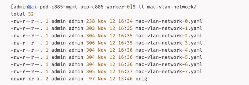
Configuration for each interface:
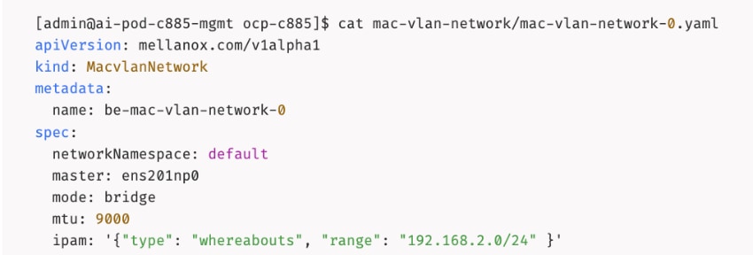
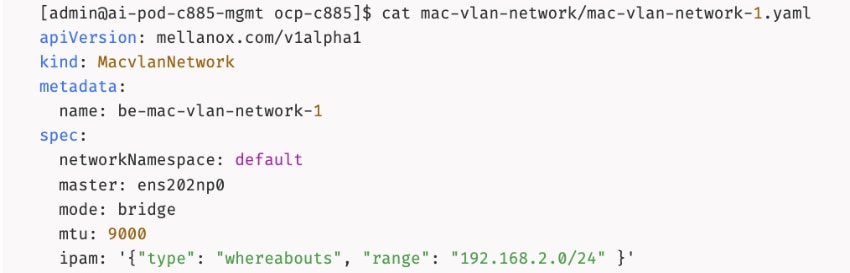
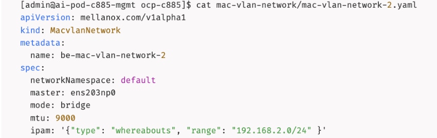
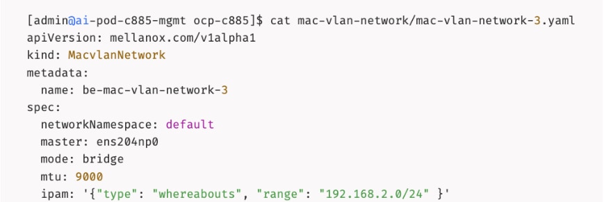
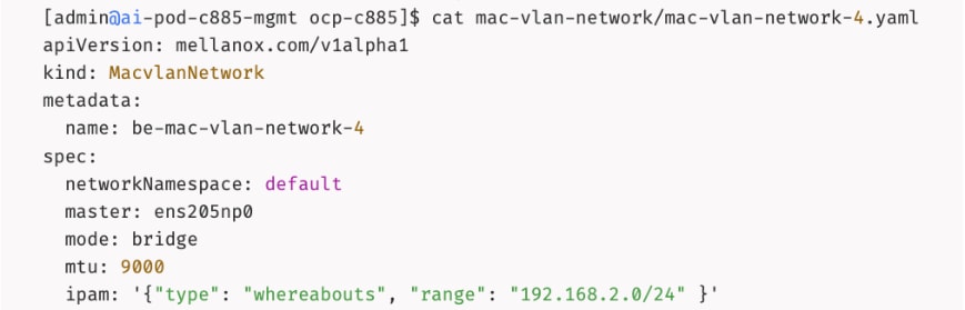
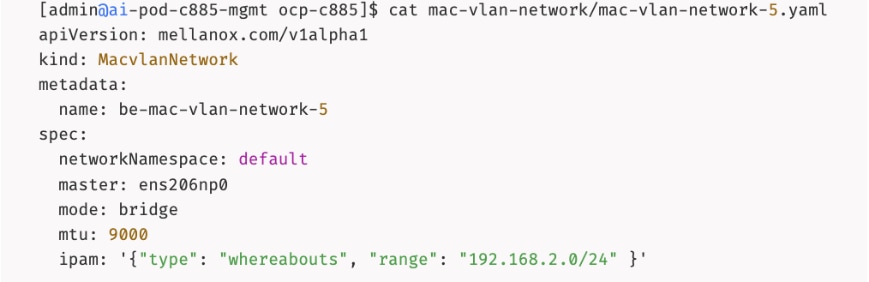
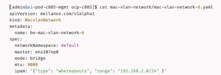
Step 6. Deploy the configuration to the OpenShift cluster:
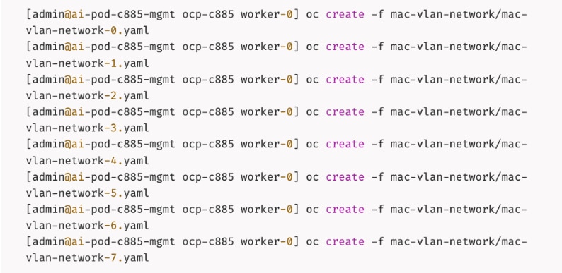
Step 7. Verify that the networks were deployed:
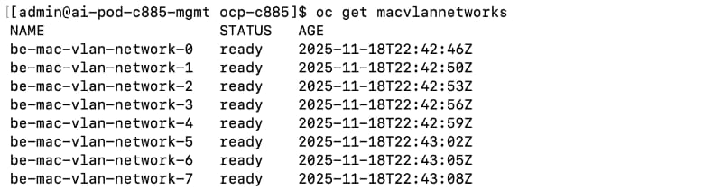
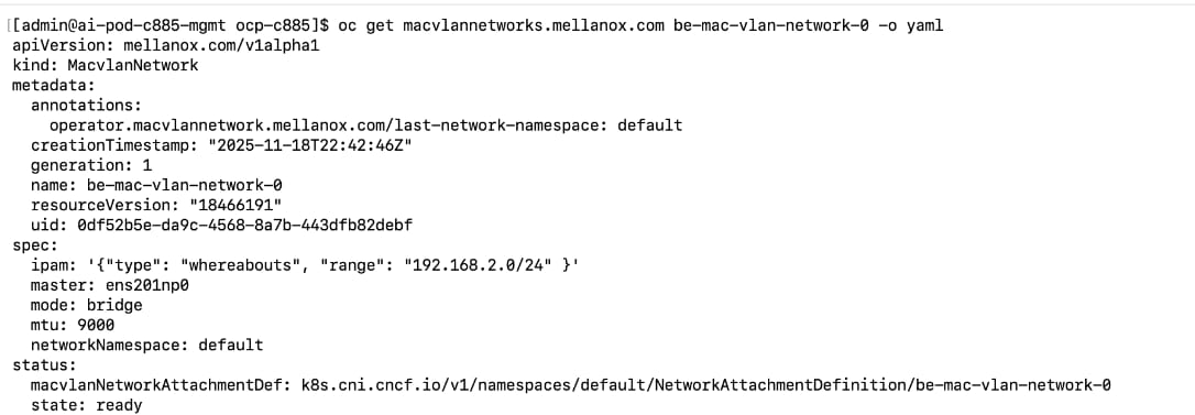
Step 8. From a browser, log into the OpenShift Cluster Console.
Step 9. From the left navigation menu, go to Operators > Installed Operators.
Step 10. Select the NVIDIA Network Operator from the list.
Step 11. From the top menu bar, select the MacvlanNetwork tab. Confirm that the State is ready for each network as shown below:
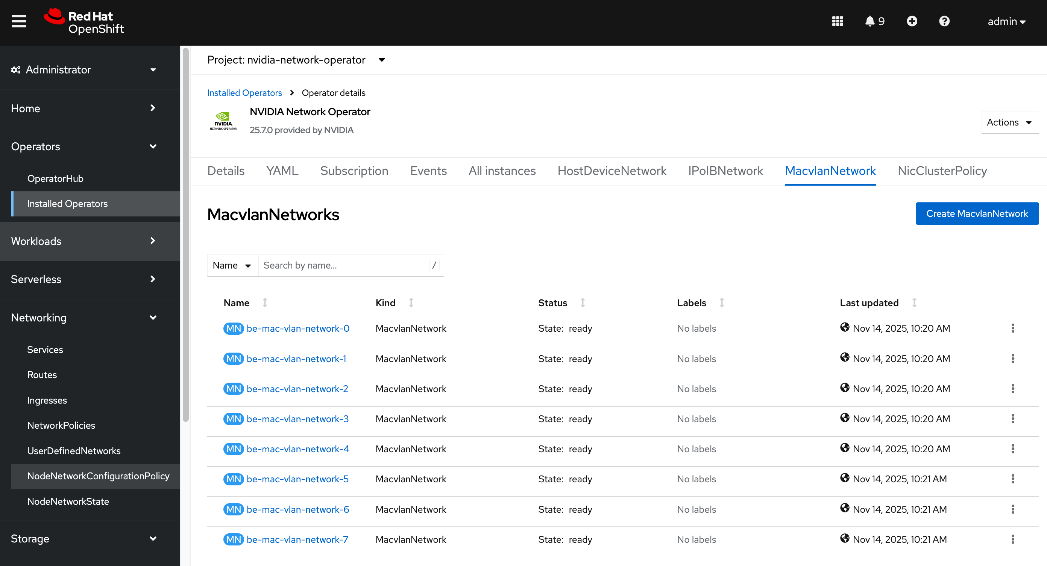
Step 12. Repeat this procedure to configure the interfaces on remaining nodes.
Deploy ARP and RP policies
When layer 2 (overlay) is used for inter-node connectivity across the backend fabric, deploy the following Address Resolution Protocol (ARP) and Reverse Path (RP) policies.
Procedure 1. Deploy ARP and RP policies
Step 1. SSH and log into the OpenShift Installer machine used to manage the OpenShift cluster.
Step 2. Go to the cluster directory and then to the previously created machine-configs sub-directory.
Step 3. Create a file (for example, arp-rp-filter.conf) with the following configuration:
sysctl -w net.ipv4.conf.all.arp_filter=0
sysctl -w net.ipv4.conf.default.arp_filter=0
sysctl -w net.ipv4.conf.all.arp_ignore=1
sysctl -w net.ipv4.conf.default.arp_ignore=1
sysctl -w net.ipv4.conf.all.rp_filter=0
sysctl -w net.ipv4.conf.default.rp_filter=0
Step 4. Convert the file into a base64 string without line breaks using the following command. Copy the output to a variable:
SOMEVAR=cat <file_name> | base64 -w 0
Step 5. Create a machineconfig file (for example, 99-machine-config-arp-rp-policies.yaml) with the following information. Insert the base64 output after `base64, in the source: section by referencing the above variable as shown below:
apiVersion: machineconfiguration.openshift.io/v1
kind: MachineConfig
metadata:
name: 99-machine-config-arp-rp-policies
labels:
machineconfiguration.openshift.io/role: worker
spec:
config:
ignition:
version: 3.2.0
systemd:
units:
- name: 99-machine-config-arp-parameters
enabled: true
contents: |
storage:
files:
- filesystem: root
path: "/etc/sysctl.d/arp-rp-filter.conf"
contents:
source: data:text/plain;charset=utf-8;base64,$SOMEVAR
verification: {}
mode: 0755
overwrite: true
Step 6. Deploy the YAML file to the OpenShift cluster:
oc apply -f 99-machine-config-arp-rp-policies.yaml
Step 7. Monitor the progress of the machine config update. Wait a few minutes.
oc get mcp
Step 8. SSH into at least one node and verify the commands took effect.
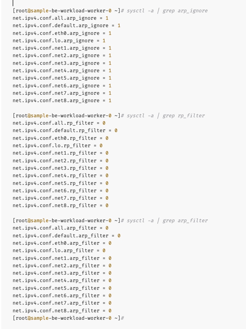
Create GPU Cluster Policy for NVIDIA GPU Operator
Procedure 1. Set up the GPU cluster policy for NVIDIA GPU operator
Step 1. From a browser, log into the OpenShift Cluster Console.
Step 2. From the left navigation menu, go to Operators > Installed Operators.
Step 3. Click the NVIDIA GPU Operator from the list.
Step 4. From the top menu, select the GPUClusterPolicy tab.
Step 5. Click Create GPUClusterPolicy on the right to create a policy.
Step 6. From YAML mode, modify the default policy by adding the following in the driver: section as shown below:
rdma:
enabled: true
Complete configs below:
apiVersion: nvidia.com/v1
kind: ClusterPolicy
metadata:
name: gpu-cluster-policy
spec:
vgpuDeviceManager:
config:
default: default
enabled: true
migManager:
config:
default: all-disabled
name: default-mig-parted-config
enabled: true
operator:
defaultRuntime: crio
initContainer: {}
runtimeClass: nvidia
use_ocp_driver_toolkit: true
dcgm:
enabled: true
gfd:
enabled: true
dcgmExporter:
config:
name: ''
serviceMonitor:
enabled: true
enabled: true
cdi:
default: false
enabled: true
driver:
licensingConfig:
nlsEnabled: true
secretName: ''
kernelModuleType: auto
certConfig:
name: ''
rdma:
enabled: true
kernelModuleConfig:
name: ''
upgradePolicy:
autoUpgrade: true
drain:
deleteEmptyDir: false
enable: false
force: false
timeoutSeconds: 300
maxParallelUpgrades: 1
maxUnavailable: 25%
podDeletion:
deleteEmptyDir: false
force: false
timeoutSeconds: 300
waitForCompletion:
timeoutSeconds: 0
repoConfig:
configMapName: ''
virtualTopology:
config: ''
enabled: true
useNvidiaDriverCRD: false
devicePlugin:
config:
name: ''
default: ''
mps:
root: /run/nvidia/mps
enabled: true
gdrcopy:
enabled: false
kataManager:
config:
artifactsDir: /opt/nvidia-gpu-operator/artifacts/runtimeclasses
mig:
strategy: single
sandboxDevicePlugin:
enabled: true
validator:
plugin:
env: []
nodeStatusExporter:
enabled: true
daemonsets:
rollingUpdate:
maxUnavailable: '1'
updateStrategy: RollingUpdate
sandboxWorkloads:
defaultWorkload: container
enabled: false
gds:
enabled: false
vgpuManager:
enabled: false
vfioManager:
enabled: true
toolkit:
installDir: /usr/local/nvidia
enabled: true
Step 7. Verify that the GPU Cluster Policy is deployed and in Ready state. You are now ready to validate GPUDirect RDMA across the backend fabric by deploying a workload on the GPU worker nodes.
This section outlines the steps taken to verify the GPUDirect RDMA configuration deployed in the previous section. Though there are multiple ways in which this can be validated, this CVD used the following approach.
Note: The GitHub repo for the tools used here is: https://github.com/schmaustech/nvidia-tools-image.
Deploy workload to test and verify GPUDirect RDMA
Procedure 1. Test and verify GPUDirect RDMA
Step 1. SSH and log into the OpenShift Installer machine used to manage the OpenShift cluster.
Step 2. Go to the cluster directory.
Step 3. Create a sub-directory to save the configuration files.
Step 4. Create a ServiceAccount YAML file with the following configuration:
apiVersion: v1
kind: ServiceAccount
metadata:
name: nvidiatools
namespace: default
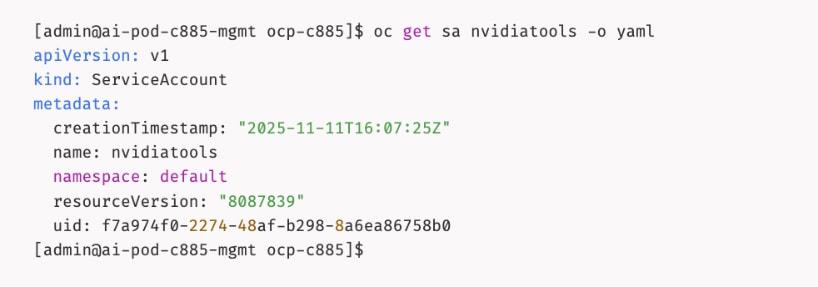
Step 5. Give priveleged access to nvidiatools:
oc -n default adm policy add-scc-to-user privileged -z nvidiatools
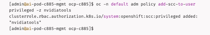
Step 6. Create sample workload pod on one node:
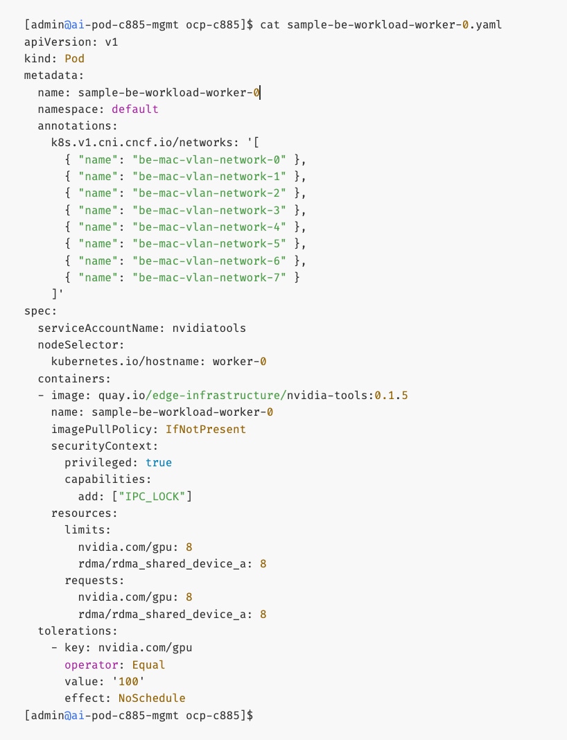
Step 7. Repeat step 6 to create another workload pod on second node. Specify a different name in the metadata and containers sections. Also specify hostname of second node in the nodeSelector section.
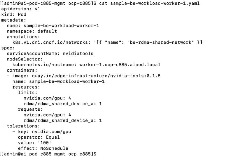
Step 8. Deploy both workloads:
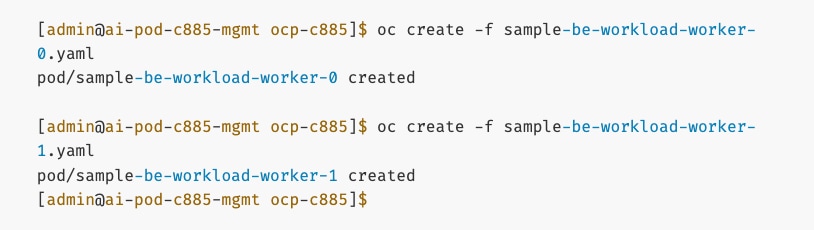
Step 9. Though the Pods are in a running state, it may take another 5min for all tools to be downloaded. Run the following commands:
oc logs sample-be-workload-worker-0
oc logs sample-be-workload-worker-1
Step 10. Look for the following in the logs:
Step 11. Note that once Pods are running, you can verify the networking setup by rsh-ing into pod:
oc rsh sample-be-workload-worker-0
oc rsh sample-be-workload-worker-1
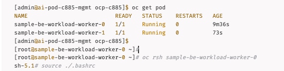
IB_WRITE Validation Tests
Procedure 2. Validate IB_Write
Step 1. SSH and log into the OpenShift Installer machine used to manage the OpenShift cluster.
Step 2. Go to the OpenShift cluster directory.
Step 3. Run the following commands to start a IB_WRITE test between two IP addresses on different UCS nodes across the backend fabric.
On the first workload Pod: Server side
[root@sample-be-workload-worker-0 ~]# ib_write_bw -R --tos=41 -s 65536 -F -x 4 -m 4096 --report_gbits -q 16 -D 60 --use_cuda=0 --use_cuda_dmabuf -d mlx5_1 -p 10000 --source_ip <local_IP_address_on_BE_NIC>
On the second workload Pod: Client side
root@sample-be-workload-worker-1 ~]# ib_write_bw -R --tos=41 -s 65536 -F -x 4 -m 4096 --report_gbits -q 16 -D 60 --use_cuda=0 --use_cuda_dmabuf -d mlx5_1 -p 10000 --source_ip <local_IP_address_on_BE_NIC> <remote_IP_address_on_BE_NIC>
Step 4. A sample output from ib_write_bw test used in CVD validation is provided below. The results show an average bandwidth of 392 Gb/s for this test run across a VXLAN backend fabric. Complete results and associated scripts are available in the AI POD GitHub repo (Validation folder).
Server side:
[root@sample-be-workload-worker-0 ~]# ib_write_bw -R --tos=41 -s 65536 -F -x 4 -m 4096 --report_gbits -q 16 -D 60 --use_cuda=0 --use_cuda_dmabuf -d mlx5_1 -p 10000 --source_ip 192.168.2.1
WARNING: BW peak won't be measured in this run.
Perftest doesn't supports CUDA tests with inline messages: inline size set to 0
************************************
* Waiting for client to connect... *
************************************
initializing CUDA
Listing all CUDA devices in system:
CUDA device 0: PCIe address is 03:00
CUDA device 1: PCIe address is 31:00
CUDA device 2: PCIe address is 51:00
CUDA device 3: PCIe address is 63:00
CUDA device 4: PCIe address is 83:00
CUDA device 5: PCIe address is AB:00
CUDA device 6: PCIe address is CB:00
CUDA device 7: PCIe address is E5:00
Picking device No. 0
[pid = 17100, dev = 0] device name = [NVIDIA H200]
creating CUDA Ctx
making it the current CUDA Ctx
CUDA device integrated: 0
using DMA-BUF for GPU buffer address at 0x7f9343e00000 aligned at 0x7f9343e00000 with aligned size 2097152
allocated GPU buffer of a 2097152 address at 0x224e0e0 for type CUDA_MEM_DEVICE
Calling ibv_reg_dmabuf_mr(offset=0, size=2097152, addr=0x7f9343e00000, fd=70) for QP #0
---------------------------------------------------------------------------------------
RDMA_Write BW Test
Dual-port : OFF Device : mlx5_1
Number of qps : 16 Transport type : IB
Connection type : RC Using SRQ : OFF
PCIe relax order: ON Lock-free : OFF
ibv_wr* API : ON Using Enhanced Reorder : OFF
CQ Moderation : 1
CQE Poll Batch : Dynamic
Mtu : 4096[B]
Link type : Ethernet
GID index : 4
Max inline data : 0[B]
rdma_cm QPs : ON
Data ex. method : rdma_cm TOS : 41
---------------------------------------------------------------------------------------
Waiting for client rdma_cm QP to connect
Please run the same command with the IB/RoCE interface IP
---------------------------------------------------------------------------------------
local address: LID 0000 QPN 0x0483 PSN 0x912d72
GID: 00:00:00:00:00:00:00:00:00:00:255:255:192:168:02:01
local address: LID 0000 QPN 0x0484 PSN 0x842f74
GID: 00:00:00:00:00:00:00:00:00:00:255:255:192:168:02:01
local address: LID 0000 QPN 0x0485 PSN 0x4bedae
GID: 00:00:00:00:00:00:00:00:00:00:255:255:192:168:02:01
local address: LID 0000 QPN 0x0486 PSN 0x6d2665
GID: 00:00:00:00:00:00:00:00:00:00:255:255:192:168:02:01
local address: LID 0000 QPN 0x0487 PSN 0x85cd14
GID: 00:00:00:00:00:00:00:00:00:00:255:255:192:168:02:01
local address: LID 0000 QPN 0x0488 PSN 0x409ee6
GID: 00:00:00:00:00:00:00:00:00:00:255:255:192:168:02:01
local address: LID 0000 QPN 0x0489 PSN 0x380d4d
GID: 00:00:00:00:00:00:00:00:00:00:255:255:192:168:02:01
local address: LID 0000 QPN 0x048a PSN 0x9213c2
GID: 00:00:00:00:00:00:00:00:00:00:255:255:192:168:02:01
local address: LID 0000 QPN 0x048b PSN 0x998f3e
GID: 00:00:00:00:00:00:00:00:00:00:255:255:192:168:02:01
local address: LID 0000 QPN 0x048c PSN 0x22ee8
GID: 00:00:00:00:00:00:00:00:00:00:255:255:192:168:02:01
local address: LID 0000 QPN 0x048d PSN 0x39e6c
GID: 00:00:00:00:00:00:00:00:00:00:255:255:192:168:02:01
local address: LID 0000 QPN 0x048e PSN 0xaa3c8f
GID: 00:00:00:00:00:00:00:00:00:00:255:255:192:168:02:01
local address: LID 0000 QPN 0x048f PSN 0xc130cf
GID: 00:00:00:00:00:00:00:00:00:00:255:255:192:168:02:01
local address: LID 0000 QPN 0x0490 PSN 0x3babd0
GID: 00:00:00:00:00:00:00:00:00:00:255:255:192:168:02:01
local address: LID 0000 QPN 0x0491 PSN 0x48c4e
GID: 00:00:00:00:00:00:00:00:00:00:255:255:192:168:02:01
local address: LID 0000 QPN 0x0492 PSN 0x2fa0fa
GID: 00:00:00:00:00:00:00:00:00:00:255:255:192:168:02:01
remote address: LID 0000 QPN 0x0483 PSN 0x65dc0b
GID: 00:00:00:00:00:00:00:00:00:00:255:255:192:168:02:02
remote address: LID 0000 QPN 0x0484 PSN 0xfbfc99
GID: 00:00:00:00:00:00:00:00:00:00:255:255:192:168:02:02
remote address: LID 0000 QPN 0x0485 PSN 0xb9846f
GID: 00:00:00:00:00:00:00:00:00:00:255:255:192:168:02:02
remote address: LID 0000 QPN 0x0486 PSN 0x73bc92
GID: 00:00:00:00:00:00:00:00:00:00:255:255:192:168:02:02
remote address: LID 0000 QPN 0x0487 PSN 0xbc2c3d
GID: 00:00:00:00:00:00:00:00:00:00:255:255:192:168:02:02
remote address: LID 0000 QPN 0x0488 PSN 0xb1f95b
GID: 00:00:00:00:00:00:00:00:00:00:255:255:192:168:02:02
remote address: LID 0000 QPN 0x0489 PSN 0x9caf1e
GID: 00:00:00:00:00:00:00:00:00:00:255:255:192:168:02:02
remote address: LID 0000 QPN 0x048a PSN 0x78bfbf
GID: 00:00:00:00:00:00:00:00:00:00:255:255:192:168:02:02
remote address: LID 0000 QPN 0x048b PSN 0x9217f7
GID: 00:00:00:00:00:00:00:00:00:00:255:255:192:168:02:02
remote address: LID 0000 QPN 0x048c PSN 0x369bad
GID: 00:00:00:00:00:00:00:00:00:00:255:255:192:168:02:02
remote address: LID 0000 QPN 0x048d PSN 0xaaec4d
GID: 00:00:00:00:00:00:00:00:00:00:255:255:192:168:02:02
remote address: LID 0000 QPN 0x048e PSN 0x4a8b5c
GID: 00:00:00:00:00:00:00:00:00:00:255:255:192:168:02:02
remote address: LID 0000 QPN 0x048f PSN 0xcaec18
GID: 00:00:00:00:00:00:00:00:00:00:255:255:192:168:02:02
remote address: LID 0000 QPN 0x0490 PSN 0xefffe5
GID: 00:00:00:00:00:00:00:00:00:00:255:255:192:168:02:02
remote address: LID 0000 QPN 0x0491 PSN 0xb3373f
GID: 00:00:00:00:00:00:00:00:00:00:255:255:192:168:02:02
remote address: LID 0000 QPN 0x0492 PSN 0x4eef97
GID: 00:00:00:00:00:00:00:00:00:00:255:255:192:168:02:02
---------------------------------------------------------------------------------------
#bytes #iterations BW peak[Gb/sec] BW average[Gb/sec] MsgRate[Mpps]
65536 22419779 0.00 392.40 0.748448
---------------------------------------------------------------------------------------
deallocating GPU buffer 00007f9343e00000
destroying current CUDA Ctx
[root@sample-be-workload-worker-0 ~]#
Client side:
root@sample-be-workload-worker-1 ~]# ib_write_bw -R --tos=41 -s 65536 -F -x 4 -m 4096 --report_gbits -q 16 -D 60 --use_cuda=0 --use_cuda_dmabuf -d mlx5_1 -p 10000 --source_ip 192.168.2.2 192.168.2.1
WARNING: BW peak won't be measured in this run.
Perftest doesn't supports CUDA tests with inline messages: inline size set to 0
initializing CUDA
Listing all CUDA devices in system:
CUDA device 0: PCIe address is 03:00
CUDA device 1: PCIe address is 31:00
CUDA device 2: PCIe address is 51:00
CUDA device 3: PCIe address is 63:00
CUDA device 4: PCIe address is 83:00
CUDA device 5: PCIe address is AB:00
CUDA device 6: PCIe address is CB:00
CUDA device 7: PCIe address is E5:00
Picking device No. 0
[pid = 17095, dev = 0] device name = [NVIDIA H200]
creating CUDA Ctx
making it the current CUDA Ctx
CUDA device integrated: 0
using DMA-BUF for GPU buffer address at 0x7fdd07e00000 aligned at 0x7fdd07e00000 with aligned size 2097152
allocated GPU buffer of a 2097152 address at 0x1679100 for type CUDA_MEM_DEVICE
Calling ibv_reg_dmabuf_mr(offset=0, size=2097152, addr=0x7fdd07e00000, fd=70) for QP #0
---------------------------------------------------------------------------------------
RDMA_Write BW Test
Dual-port : OFF Device : mlx5_1
Number of qps : 16 Transport type : IB
Connection type : RC Using SRQ : OFF
PCIe relax order: ON Lock-free : OFF
ibv_wr* API : ON Using Enhanced Reorder : OFF
TX depth : 128
CQ Moderation : 1
CQE Poll Batch : Dynamic
Mtu : 4096[B]
Link type : Ethernet
GID index : 4
Max inline data : 0[B]
rdma_cm QPs : ON
Data ex. method : rdma_cm TOS : 41
---------------------------------------------------------------------------------------
local address: LID 0000 QPN 0x0483 PSN 0x65dc0b
GID: 00:00:00:00:00:00:00:00:00:00:255:255:192:168:02:02
local address: LID 0000 QPN 0x0484 PSN 0xfbfc99
GID: 00:00:00:00:00:00:00:00:00:00:255:255:192:168:02:02
local address: LID 0000 QPN 0x0485 PSN 0xb9846f
GID: 00:00:00:00:00:00:00:00:00:00:255:255:192:168:02:02
local address: LID 0000 QPN 0x0486 PSN 0x73bc92
GID: 00:00:00:00:00:00:00:00:00:00:255:255:192:168:02:02
local address: LID 0000 QPN 0x0487 PSN 0xbc2c3d
GID: 00:00:00:00:00:00:00:00:00:00:255:255:192:168:02:02
local address: LID 0000 QPN 0x0488 PSN 0xb1f95b
GID: 00:00:00:00:00:00:00:00:00:00:255:255:192:168:02:02
local address: LID 0000 QPN 0x0489 PSN 0x9caf1e
GID: 00:00:00:00:00:00:00:00:00:00:255:255:192:168:02:02
local address: LID 0000 QPN 0x048a PSN 0x78bfbf
GID: 00:00:00:00:00:00:00:00:00:00:255:255:192:168:02:02
local address: LID 0000 QPN 0x048b PSN 0x9217f7
GID: 00:00:00:00:00:00:00:00:00:00:255:255:192:168:02:02
local address: LID 0000 QPN 0x048c PSN 0x369bad
GID: 00:00:00:00:00:00:00:00:00:00:255:255:192:168:02:02
local address: LID 0000 QPN 0x048d PSN 0xaaec4d
GID: 00:00:00:00:00:00:00:00:00:00:255:255:192:168:02:02
local address: LID 0000 QPN 0x048e PSN 0x4a8b5c
GID: 00:00:00:00:00:00:00:00:00:00:255:255:192:168:02:02
local address: LID 0000 QPN 0x048f PSN 0xcaec18
GID: 00:00:00:00:00:00:00:00:00:00:255:255:192:168:02:02
local address: LID 0000 QPN 0x0490 PSN 0xefffe5
GID: 00:00:00:00:00:00:00:00:00:00:255:255:192:168:02:02
local address: LID 0000 QPN 0x0491 PSN 0xb3373f
GID: 00:00:00:00:00:00:00:00:00:00:255:255:192:168:02:02
local address: LID 0000 QPN 0x0492 PSN 0x4eef97
GID: 00:00:00:00:00:00:00:00:00:00:255:255:192:168:02:02
remote address: LID 0000 QPN 0x0483 PSN 0x912d72
GID: 00:00:00:00:00:00:00:00:00:00:255:255:192:168:02:01
remote address: LID 0000 QPN 0x0484 PSN 0x842f74
GID: 00:00:00:00:00:00:00:00:00:00:255:255:192:168:02:01
remote address: LID 0000 QPN 0x0485 PSN 0x4bedae
GID: 00:00:00:00:00:00:00:00:00:00:255:255:192:168:02:01
remote address: LID 0000 QPN 0x0486 PSN 0x6d2665
GID: 00:00:00:00:00:00:00:00:00:00:255:255:192:168:02:01
remote address: LID 0000 QPN 0x0487 PSN 0x85cd14
GID: 00:00:00:00:00:00:00:00:00:00:255:255:192:168:02:01
remote address: LID 0000 QPN 0x0488 PSN 0x409ee6
GID: 00:00:00:00:00:00:00:00:00:00:255:255:192:168:02:01
remote address: LID 0000 QPN 0x0489 PSN 0x380d4d
GID: 00:00:00:00:00:00:00:00:00:00:255:255:192:168:02:01
remote address: LID 0000 QPN 0x048a PSN 0x9213c2
GID: 00:00:00:00:00:00:00:00:00:00:255:255:192:168:02:01
remote address: LID 0000 QPN 0x048b PSN 0x998f3e
GID: 00:00:00:00:00:00:00:00:00:00:255:255:192:168:02:01
remote address: LID 0000 QPN 0x048c PSN 0x22ee8
GID: 00:00:00:00:00:00:00:00:00:00:255:255:192:168:02:01
remote address: LID 0000 QPN 0x048d PSN 0x39e6c
GID: 00:00:00:00:00:00:00:00:00:00:255:255:192:168:02:01
remote address: LID 0000 QPN 0x048e PSN 0xaa3c8f
GID: 00:00:00:00:00:00:00:00:00:00:255:255:192:168:02:01
remote address: LID 0000 QPN 0x048f PSN 0xc130cf
GID: 00:00:00:00:00:00:00:00:00:00:255:255:192:168:02:01
remote address: LID 0000 QPN 0x0490 PSN 0x3babd0
GID: 00:00:00:00:00:00:00:00:00:00:255:255:192:168:02:01
remote address: LID 0000 QPN 0x0491 PSN 0x48c4e
GID: 00:00:00:00:00:00:00:00:00:00:255:255:192:168:02:01
remote address: LID 0000 QPN 0x0492 PSN 0x2fa0fa
GID: 00:00:00:00:00:00:00:00:00:00:255:255:192:168:02:01
---------------------------------------------------------------------------------------
#bytes #iterations BW peak[Gb/sec] BW average[Gb/sec] MsgRate[Mpps]
65536 22419779 0.00 392.40 0.748448
---------------------------------------------------------------------------------------
deallocating GPU buffer 00007fdd07e00000
destroying current CUDA Ctx
[root@sample-be-workload-worker-1 ~]#
NCCL Validation Tests
Procedure 1. Validate NCCL
Step 1. SSH and log into the OpenShift Installer machine used to manage the OpenShift cluster.
Step 2. Go to the OpenShift cluster directory.
Step 3. Run the following commands to verify the setup:
oc get pods
From mofed container in the mofed pod for NVIDIA Network Operator: ibdev2netdev -v
oc rsh sample-be-workload-worker-0
source ./.bashrc
show_gids
rdma link
mst status -v
nvidia-smi topo -m
show_gids
ip_a
arp -na
netstat -rn
sysctl -a | grep arp_ignore
sysctl -a | grep arp_filter
sysctl -a | grep rp_ filter
ping <ip_address_of_all_remote_be_interfaces>
Step 4. Run the following commands to start a NCCL test between two IP addresses on different UCS nodes across the backend fabric:
mpirun --allow-run-as-root \
-H <Node1_IP_Address>,<Node2_IP_Address>, \
-np 2 \
-bind-to none -map-by slot \
-mca btl ^openib \
-mca plm_rsh_args "-p 20024" \
-x NCCL_DEBUG=VERSION \
all_reduce_perf -b 8 -e 16G -f2 -g 8
Step 5. A sample output from the all_reduce_perf test between two Cisco UCS C885A nodes across a VXLAN backend fabric is shown below. Results show a busBw of 387GB/s for this test run across the nodes using 16 H200 GPUs.
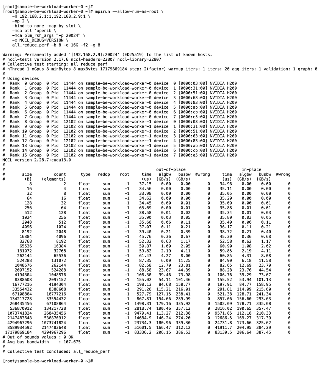
Set up Portworx for NFS over RDMA Access to Storage
Assumptions and Prerequisites
● GPUDirect RDMA across the backend fabric was deployed and validated using NVIDIA GPU and NIC Operators and associated cluster policies
● Portworx, using NFS over TCP to FlashBlade//S, was deployed and validated
Setup Information
This information is provided in line with the deployment steps.
Deployment Steps
To provision Portworx to use NFS RDMA to access storage on Everpure FlashBlade, complete the procedures in this section.
Provision Kubernetes storage class to use NFS over RDMA with Portworx backed by FlashBlade
Procedure 1. Set up Kubernetes storage class for NFS over RDMA
Step 1. SSH into the OpenShift installer workstation.
Step 2. Go to the portworx sub-directory in the OpenShift cluster directory.
Step 3. Create a new storage class configuration (.yaml file) as shown below:
kind: StorageClass
apiVersion: storage.k8s.io/v1
metadata:
name: px-fb-sc-3054-nfs-rdma
provisioner: pxd.portworx.com
parameters:
pure_nfs_endpoint: "192.168.54.15"
pure_export_rules: '*(rw,no_root_squash)'
backend: "pure_file"
volumeBindingMode: Immediate
mountOptions:
- proto=rdma
- nconnect=16
reclaimPolicy: Delete
allowVolumeExpansion: true
Step 4. Create and deploy the storage class to the OpenShift cluster:
oc apply -f <storage_class_config.yaml>
Step 5. (Optional) Make the provisioned storage class the default class:
oc patch storageclass <storage_class_name.yaml> -p '{"metadata": {"annotations": {"storageclass.kubernetes.io/is-default-class": "true"}}}'
Step 6. Use oc get storageclasses.storage.k8s.io to view all storage classes, including the default classes.
Step 7. Use the command below to view the deployed storage class:
oc get storageclass <storage_class_name> -o yaml
The deployed configuration is shown below:
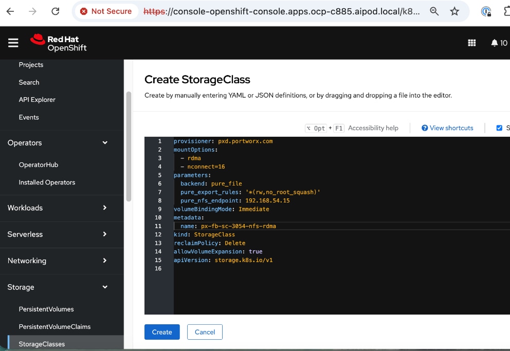
Put Portworx in maintenance mode
Before making changes to the NIC Cluster Policy in the next procedure, put Portworx into maintenance mode on the Cisco UCS C885A nodes using the following procedure.
Procedure 1. Set up Portworx in maintenance mode
Step 1. SSH into the OpenShift installer workstation.
Step 2. Go to the OpenShift cluster directory.
Step 3. Delete or migrate applications using Portworx to non-UCS C885A nodes in the cluster:
oc adm cordon <node>
oc delete pod <pod-name>
Step 4. Enter maintenance mode:
pxctl service maintenance --enter
Remove previously deployed NVIDIA GPU operator
This is an optional but recommended step to remove the previously deployed NVIDIA GPU operator so as to prevent potential conflicts. The NVIDIA GPU Operator will be re-deployed later, after the NVIDIA Network Operator is deployed.
Procedure 1. Remove deployed NVIDIA GPU operator
Step 1. From a browser to go and log into the OpenShift Cluster Console.
Step 2. From the left navigation menu, go to Operators > Installed Operators.
Step 3. Filter on NVIDIA in the Search box.
Step 4. Click the ellipses to the right of NVIDIA GPU Operator and select Uninstall Operator in the pop-up.
Update NVIDIA NIC Cluster policy to use RDMA
Procedure 1. Configure NVIDIA NIC cluster policy to use RDMA
Step 1. From a browser, log into the OpenShift Cluster Console.
Step 2. From the left navigation menu, go to Operators > Installed Operators.
Step 3. Click the NVIDIA Network Operator from the list.
Step 4. From the top menu, select the NicClusterPolicy tab.
Step 5. Right-click the ellipses to the right of existing NIC cluster Policy and edit the policy.
Step 6. Add the following to the existing NVIDIA NIC Cluster Policy (in the spec: section) as shown below:
env:
- name: ENABLE_NFSRDMA
value: 'true'

Step 7. Click Save.
Step 8. Verify that NIC Cluster Policy state is in Ready state.
Step 9. SSH and log into the OpenShift Installer machine used to manage the OpenShift cluster.
Step 10. Go to the cluster directory and then to the previously created machine-configs sub-directory.
Step 11. Save the deployed NicClusterPolicy as a new YAML file (for example, nic-cluster-policy-nfs-rdma.yaml). Note that this configuration file will be slightly different from what you’d use to do an initial deployment. This version will have post-deployment info as shown but has the core configuration is still intact.
Step 12. Verify the that the mofed pods on each node are up and running:
oc get pods -n nvidia-network-operator
Step 13. Verify the that all containers in the mofed pods are up and running. Confirm for each node. If mofed pods and containers are up and running, it is likely that the correct mofed drivers got loaded.
oc describe pod <mofed_pod_name>
Deploy GPU Cluster Policy and Cluster Policy
The GPU Cluster Policy was deployed in the Deploy GPUDirect RDMA section Procedure 8. Create GPU Cluster Policy for NVIDIA GPU Operator. If you removed it before reconfiguring the NIC Cluster policy, this serves as a reminder to re-deploy the GPU Cluster policy using the procedures provided in the earlier section.
Note: No configuration changes to GPU Cluster Policy
Take Portworx out of maintenance mode
Procedure 1. Remove Portworx from maintenance mode on the Cisco UCS C885A nodes
Step 1. SSH into the OpenShift installer workstation.
Step 2. Go to the OpenShift cluster directory.
Step 3. Exit maintenance mode:
pxctl service maintenance --exit
Step 4. Put node back into use:
oc adm uncordon <node>
Set up Portworx for GPUDirect Storage
For more information on GPUDirect Storage Configuration and Benchmarking, see: https://docs.nvidia.com/gpudirect-storage/configuration-guide/index.html
Assumptions and Prerequisites
● GPUDirect RDMA across the backend fabric was deployed and validated using NVIDIA GPU and NIC Operators and associated cluster policies
● Portworx, using NFS over RDMA to FlashBlade//S, was deployed and validated
Setup Information
This information is provided in line with the deployment steps.
Deployment Steps
To provision Portworx to use GPUDirect Storage to access storage on Everpure FlashBlade, complete the procedures in this section.
Provision Kubernetes storage class for GDS with Portworx backed by FlashBlade
Procedure 1. Provision Kubernetes storage class
Step 1. SSH into the OpenShift installer workstation.
Step 2. Go to the portworx sub-directory in the OpenShift cluster directory.
Step 3. Create a new storage class configuration (.yaml file) as shown below.
Note: Storage class configuration is the same for GDS and NFS over RDMA.
kind: StorageClass
apiVersion: storage.k8s.io/v1
metadata:
name: px-fb-sc-3054-gds
provisioner: pxd.portworx.com
parameters:
pure_nfs_endpoint: "192.168.54.15"
pure_export_rules: '*(rw,no_root_squash)'
backend: "pure_file"
volumeBindingMode: Immediate
mountOptions:
- proto=rdma
- nconnect=16
reclaimPolicy: Delete
allowVolumeExpansion: true
Step 4. Create and deploy the storage class to the OpenShift cluster:
oc apply -f <storage_class_config.yaml>
Step 5. (Optional) Make the provisioned storage class the default class:
oc patch storageclass <storage_class_name.yaml> -p '{"metadata": {"annotations": {"storageclass.kubernetes.io/is-default-class": "true"}}}'
Step 6. Use oc get storageclasses.storage.k8s.io to view all storage classes, including the default classes.
Step 7. Use the command below to view the deployed storage class:
oc get storageclass <storage_class_name> -o yaml
The deployed configuration is shown below:
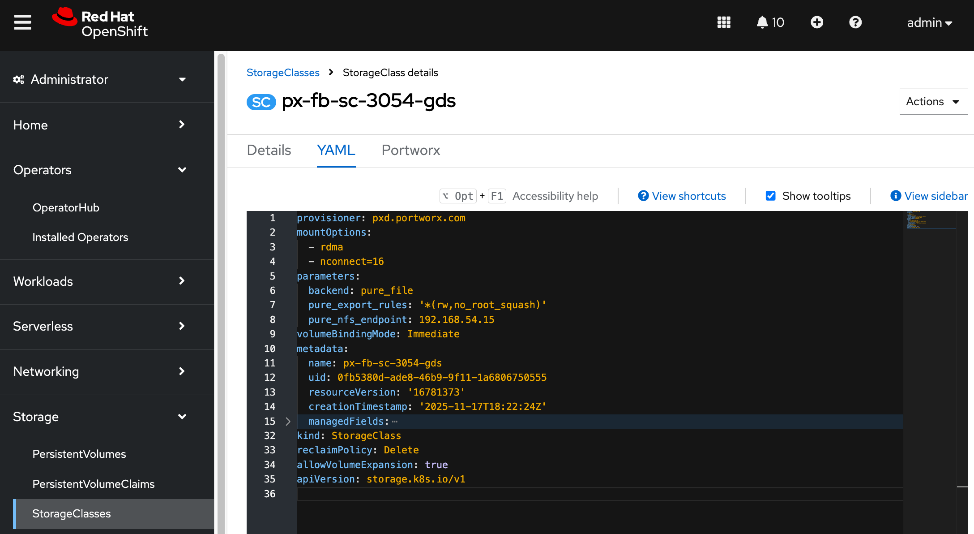
Put Portworx in maintenance mode
Before making changes to the NIC Cluster Policy in the next procedure, put Portworx into maintenance mode on the Cisco UCS C885A nodes using the following procedure.
Procedure 1. Set up Portworx in maintenance mode
Step 1. SSH into the OpenShift installer workstation.
Step 2. Go to the OpenShift cluster directory.
Step 3. Delete or migrate applications using Portworx to non-UCS C885A nodes in the cluster:
oc adm cordon <node>
oc delete pod <pod-name>
Step 4. Enter maintenance mode:
pxctl service maintenance --enter
Remove previously deployed NVIDIA GPU operator
This is an optional but recommended step to remove the previously deployed NVIDIA GPU operator so as to avoid any potential conflicts. The NVIDIA GPU Operator will be re-deployed later, after the NVIDIA Network Operator is deployed.
Procedure 1. Remove deployed NVIDIA GPU operator
Step 1. From a browser, log into the OpenShift Cluster Console.
Step 2. From the left navigation menu, go to Operators > Installed Operators.
Step 3. Filter on NVIDIA in the Search box.
Step 4. Click the ellipses to the right of NVIDIA GPU Operator and select Uninstall Operator in the pop-up.
Update NVIDIA NIC Cluster policy to use RDMA
Procedure 1. Set up NVIDIA NIC cluster policy to use RDMA
Step 1. From a browser, log into the OpenShift Cluster Console.
Step 2. From the left navigation menu, go to Operators > Installed Operators.
Step 3. Click the NVIDIA Network Operator from the list.
Step 4. From the top menu, select the NicClusterPolicy tab.
Step 5. Right-click the ellipses to the right of existing NIC cluster Policy and edit the policy.
Step 6. Add the following to the existing NVIDIA NIC Cluster Policy (in the spec: section) as shown below:
ofedDriver:
env:
- name: ENABLE_NFSRDMA
value: 'true'
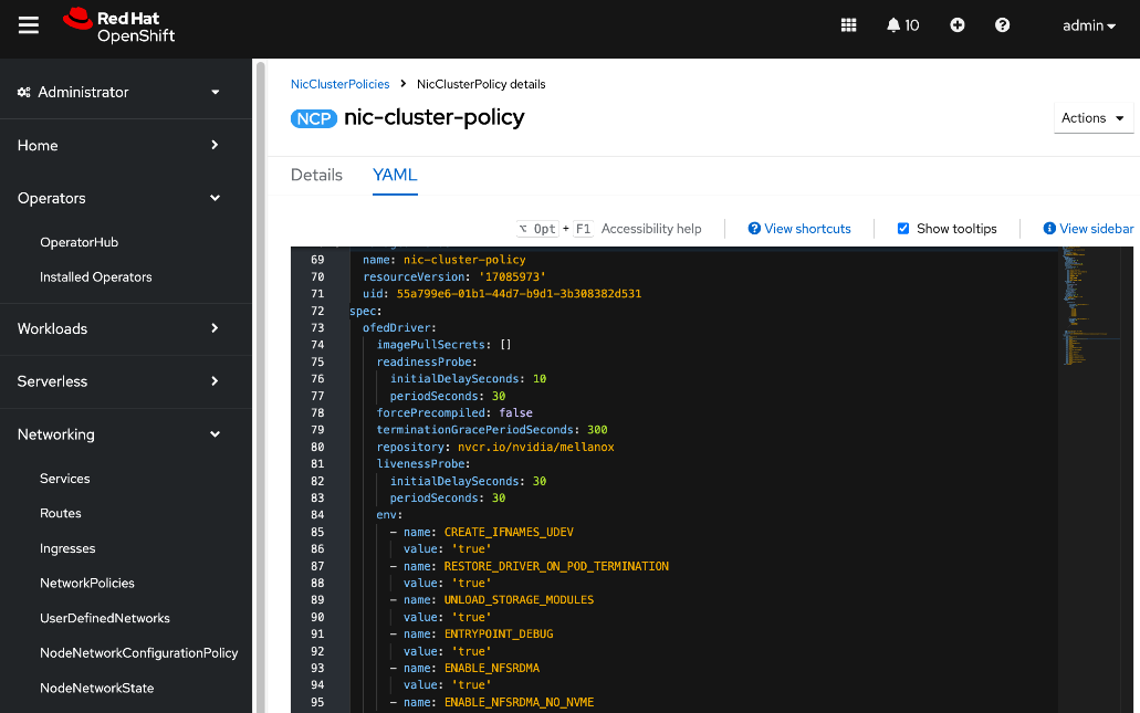
Step 7. Add a new resourceName to the policy, in the rdmaSharedDevicePlugin: section. The interfaces name should reflect the frontend NIC interfaces
Note: Add a comma to the end of first resource such as resourceName: rdma_shared_device_a before adding the following:
config: |
{
"configList": [
},
"resourceName": "rdma_shared_device_b",
"rdmaHcaMax": 63,
"selectors": {
"ifNames": [
"ens213f0np0",
"ens213f1np1"
]
}
}
]
}
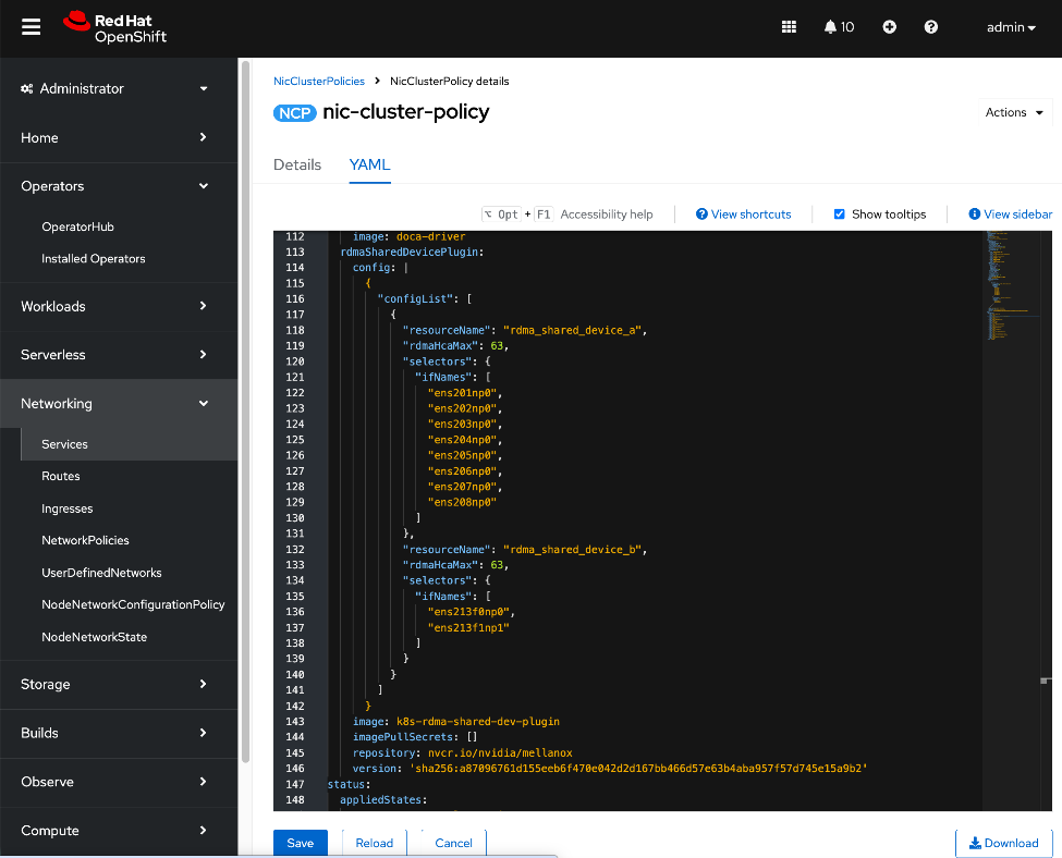
Step 8. Click Save.
Step 9. Verify that the NIC Cluster Policy state is in Ready state.
Step 10. SSH and log into the OpenShift Installer machine used to manage the OpenShift cluster.
Step 11. Go to the cluster directory and then to the previously created machine-configs sub-directory.
Step 12. Save the deployed NicClusterPolicy as a new YAML file (for example, nic-cluster-policy-gds.yaml). Note that this configuration file will be slightly different from what you’d use to do an initial deployment. This version will have post-deployment info as shown but has the core configuration is still intact.
Step 13. Verify the that the mofed pods on each node are up and running:
oc get pods -n nvidia-network-operator
Step 14. Verify the that all containers in the mofed pods are up and running. Confirm for each node. If mofed pods and containers are up and running, it is likely that the correct mofed drivers got loaded:
oc describe pod <mofed_pod_name>
Deploy GPU Operator and Cluster Policy
The GPU Cluster Policy was deployed in the Deploy GPUDirect RDMA. If you removed it before reconfiguring the NIC Cluster policy, this serves as a reminder to re-deploy the GPU Cluster policy using the procedures provided below.
Procedure 1. Deploy GPU operator and cluster policy
Step 1. From a browser, log into OpenShift Cluster Console.
Step 2. From the left navigation menu, navigate to Operators > Operator Hub.
Step 3. In the search box, enter GPU Operator.
Step 4. Click the (Certified) NVIDIA GPU Operator tile.
Step 5. Click Install.
Step 6. Keep the default settings (A specific namespace on the cluster: nvidia-gpu-operator) and click Install again.
Step 7. When the installation completes, click View Operator.
Step 8. From the top menu, select the GPUClusterPolicy tab.
Step 9. Click Create GPUClusterPolicy on the right to create a policy.
Step 10. From YAML mode, modify the default policy by adding the following in the driver: section as shown.
rdma:
enabled: true
gds:
enabled: true
image: nvidia-fs
repository: nvcr.io/nvidia/cloud-native
version: 2.26.6
The above image details will result in the following GDS driver to be loaded (view from NGC catalog).
Step 11. Complete configs below:
apiVersion: nvidia.com/v1
kind: ClusterPolicy
metadata:
name: gpu-cluster-policy
spec:
vgpuDeviceManager:
config:
default: default
enabled: true
migManager:
config:
default: all-disabled
name: default-mig-parted-config
enabled: true
operator:
defaultRuntime: crio
initContainer: {}
runtimeClass: nvidia
use_ocp_driver_toolkit: true
dcgm:
enabled: true
gfd:
enabled: true
dcgmExporter:
config:
name: ''
serviceMonitor:
enabled: true
enabled: true
cdi:
default: false
enabled: true
driver:
licensingConfig:
nlsEnabled: true
secretName: ''
kernelModuleType: auto
certConfig:
name: ''
rdma:
enabled: true
kernelModuleConfig:
name: ''
upgradePolicy:
autoUpgrade: true
drain:
deleteEmptyDir: false
enable: false
force: false
timeoutSeconds: 300
maxParallelUpgrades: 1
maxUnavailable: 25%
podDeletion:
deleteEmptyDir: false
force: false
timeoutSeconds: 300
waitForCompletion:
timeoutSeconds: 0
repoConfig:
configMapName: ''
virtualTopology:
config: ''
enabled: true
useNvidiaDriverCRD: false
devicePlugin:
config:
name: ''
default: ''
mps:
root: /run/nvidia/mps
enabled: true
gdrcopy:
enabled: false
kataManager:
config:
artifactsDir: /opt/nvidia-gpu-operator/artifacts/runtimeclasses
mig:
strategy: single
sandboxDevicePlugin:
enabled: true
validator:
plugin:
env: []
nodeStatusExporter:
enabled: true
daemonsets:
rollingUpdate:
maxUnavailable: '1'
updateStrategy: RollingUpdate
sandboxWorkloads:
defaultWorkload: container
enabled: false
gds:
enabled: true
image: nvidia-fs
repository: nvcr.io/nvidia/cloud-native
version: 2.26.6
vgpuManager:
enabled: false
vfioManager:
enabled: true
toolkit:
installDir: /usr/local/nvidia
enabled: true
Step 12. Verify that the GPU Cluster Policy is deployed and in Ready state.
Take Portworx out of maintenance mode
Procedure 1. Remove Portworx from maintenance mode on the Cisco UCS C885A nodes
Step 1. SSH into the OpenShift installer workstation.
Step 2. Navigate to the OpenShift cluster directory.
Step 3. Exit maintenance mode:
pxctl service maintenance --exit
Step 4. Put node back into use:
oc adm uncordon <node>
Deploy Red Hat OpenShift AI for MLOps
Red Hat OpenShift AI is a complete platform for the entire lifecycle of your AI/ML projects. In this section, you will deploy Red Hat OpenShift AI as an MLOPs platform in the solution to accelerate your AI/ML projects.
Deployment Steps
The first half of this section focusses on enabling KServe single-model serving platform to serve large models such as Large Language Models (LLMs) in Red Hat OpenShift AI. If you’re only using OpenShift AI for multi-model serving, then you can skip this section. KServe orchestrates model serving for different types of models and includes model-serving runtimes that support a range of AI frameworks.
For this CVD, KServe is deployed in advanced deployment mode which uses Knative serverless, deployed using OpenShift Serverless Operator. Automated Install of KServe is deployed on the OpenShift cluster by configuring OpenShift AI Operator to configure KServe and its dependencies. KServe requires a cluster with a node that has at least 4 CPUs and 16GB of memory.
Note: See the Red Hat documentation for the most uptodate information on the prerequisites for a given OpenShift AI release. For the procedures outlined in this section, see this documentation
Deploy Red Hat OpenShift Service Mesh Operator on a OpenShift Cluster
To support KServe for single-model serving, deploy Red Hat OpenShift Service Mesh Operator on OpenShift cluster as detailed below.
Note: At the time of the writing of this CVD, only OpenShift Service Mesh v2 is supported. Also, only deploy the operator is deployed - no additional configuration should be done for automatied install of KServe.
Procedure 1. Deploy Red Hat OpenShift service mesh operator on a OpenShift cluster
Step 1. From a browser, log into the OpenShift Cluster Console.
Step 2. Go to Operators > Operator Hub and search for OpenShift Service Mesh.
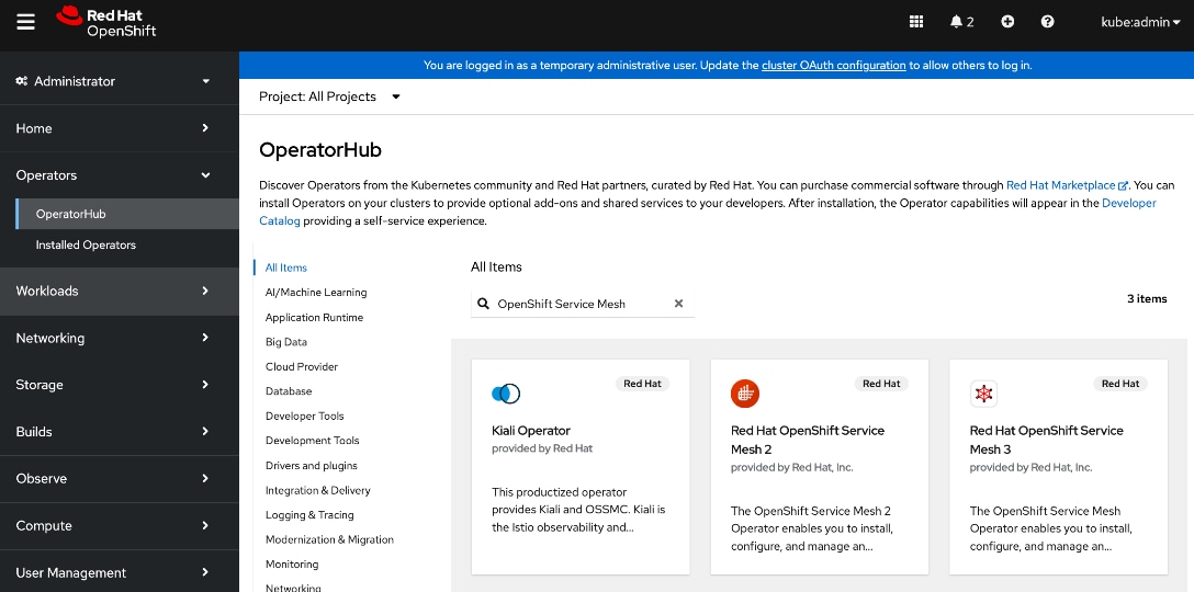
Step 3. Click the Red Hat OpenShift Service Mesh 2 tile.
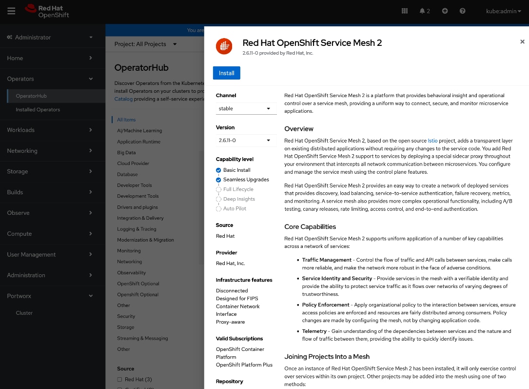
Step 4. Click Install.
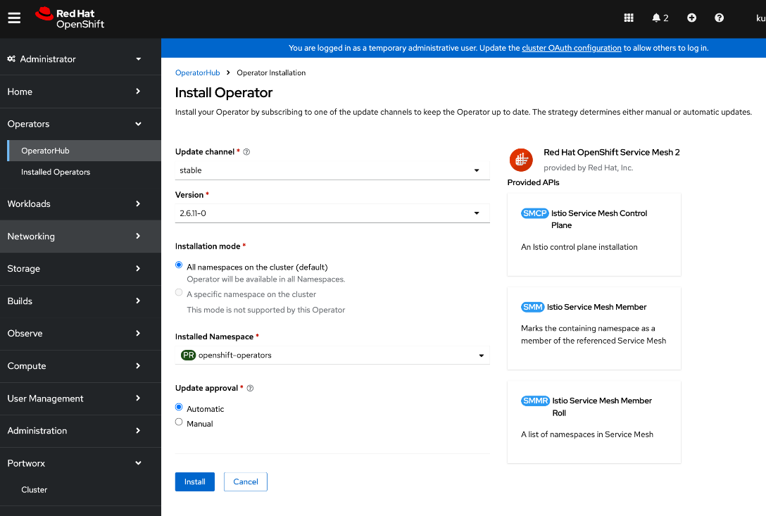
Step 5. Keep the default settings. The operator will be deployed in the openshift-operators namespace.
Step 6. Click Install.
Step 7. Click View Operator and verify that the operator deployed successfully.
Deploy Red Hat OpenShift Serverless on OpenShift cluster
To support KServe for single-model serving, deploy the Red Hat OpenShift Serverless Operator on the OpenShift cluster as detailed below.
Note: Only deploy the operator – no additional configuration should be done for automatied install of KServe.
Procedure 1. Deploy Red Hat OpenShift Serverless on OpenShift cluster
Step 1. From a browser, log into the OpenShift Cluster Console.
Step 2. Go to Operators > Operator Hub and search for OpenShift Serverless.
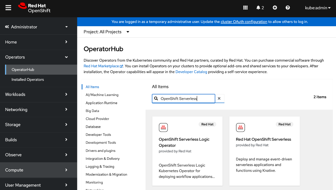
Step 3. Click the Red Hat OpenShift Serverless tile.
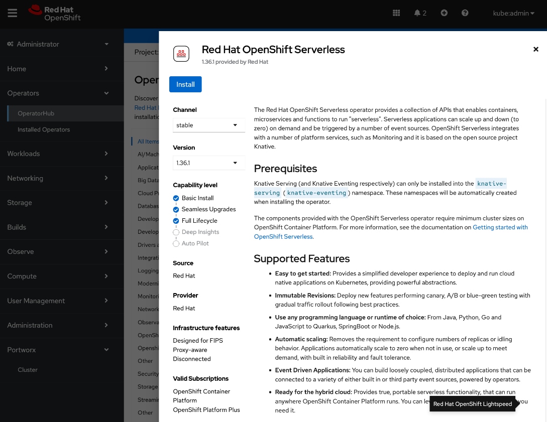
Step 4. Click Install.
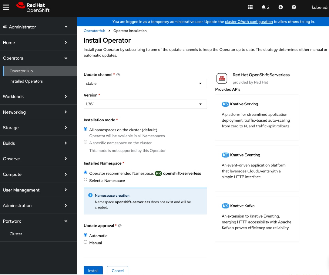
Step 5. Keep the default settings. The operator will be deployed in a new openshift-serverless namespace.
Step 6. Click Install.
Step 7. Click View Operator and verify that the operator deployed successfully.
Deploy Red Hat Authorino on OpenShift Cluster
To support KServe for single-model serving, deploy the Red Hat Authoring Operator on the OpenShift cluster to add an authorization provider as detailed below.
Note: Only deploy the operator – no additional configuration should be done for automatied install of KServe.
Procedure 1. Deploy Red Hat Authorino on OpenShift cluster
Step 1. From a browser, log into the OpenShift Cluster Console.
Step 2. Go to Operators > Operator Hub and search for Authorino.
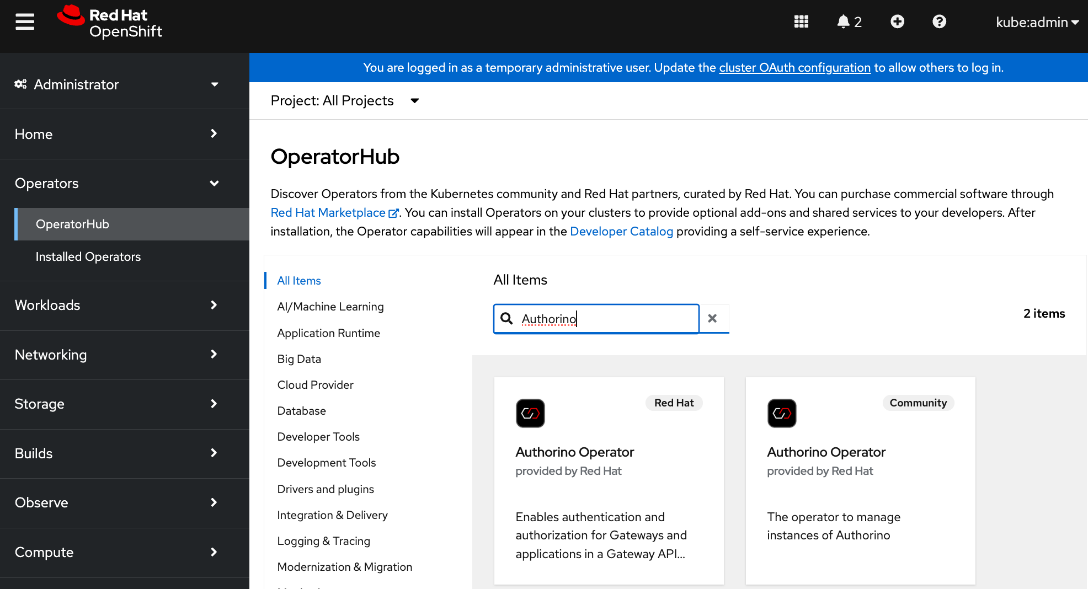
Step 3. Click the Red Hat – Authorino Operator tile.
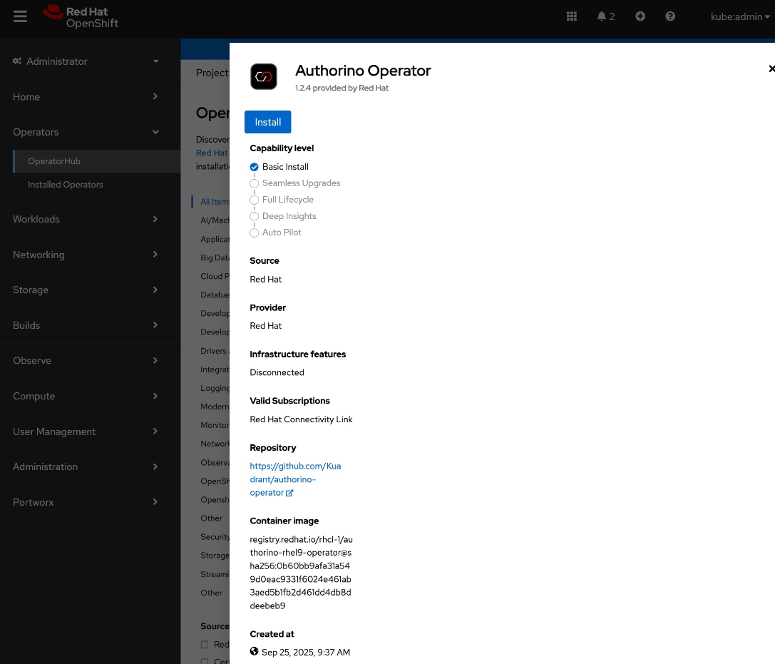
Step 4. Click Install.
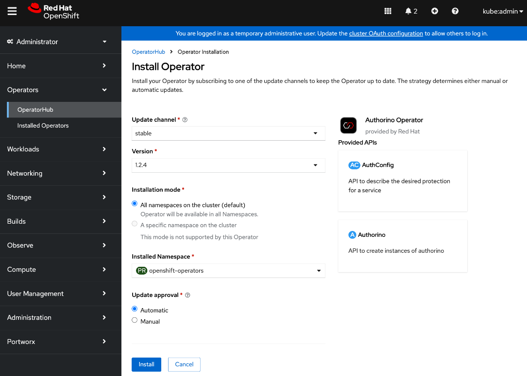
Step 5. Keep the default settings. The operator will be deployed in the openshift-operators namespace.
Step 6. Click Install.
Step 7. Click View Operator and verify that the operator deployed successfully.
Deploy Red Hat OpenShift AI Operator
This section details the procedures for deploying Red Hat Openshift AI on a Red Hat OpenShift cluster to enable an MLOps platform to develop and operationalize AI/ML use cases.
Prerequisites
● OpenShift cluster deployed with a minimum of 2 worker nodes, each with at least 8 CPUs and 32 GiB RAM available for OpenShift AI to use. Additional cluster resources maybe required depending on the needs of the individual AI/ML projects supported by OpenShift AI.
● OpenShift cluster is configured to use a default storage class that can be dynamically provisioned to provide persistent storage.
● Access to S3-compatible object store with write access.
● Model Repo to store models that will used for model serving in inferencing use cases
◦ Pipeline Artifacts to store data science pipeline runs logs, results and other artifacts or metadata.
◦ Data storage to store large data sets that maybe used by data scientists to test or experiment with.
◦ Input or Output data for Distributed Workloads
● Identity provider configured for OpenShift AI (same as Red Hat OpenShift Container Platform). You cannot use OpenShift administrator (kubeadmin) for OpenShift AI. You will need to define a separate user with cluster-admin role to access OpenShift AI.
● Internet Access, specifically access to the following locations. cdn.redhat.com
◦ subscription.rhn.redhat.com
◦ registry.access.redhat.com
◦ registry.redhat.io
◦ quay.io
● If using NVIDIA GPUs and other NIVIDA resources, then above access should include:
◦ ngc.download.nvidia.cn
◦ developer.download.nvidia.com
● Verify that the following perquisites from the previous section have been successfully deployed. The following are required to support the different uses cases that were validated as a part of this solution. See Solution Validation section of this document for more details on these use cases.
◦ Red Hat OpenShift Serverless Operator to support single-model serving of large models using Kserve.
◦ Red Hat OpenShift Service Mesh to support single-model serving.
◦ Red Hat Authorino Operator to add an authorization provider to support single-model serving.
Procedure 1. Deploy Red Hat OpenShift AI Operator on the OpenShift Cluster
Step 1. From a browser, log into the OpenShift Cluster Console.
Step 2. Go to Operators > Operator Hub and search for OpenShift AI.
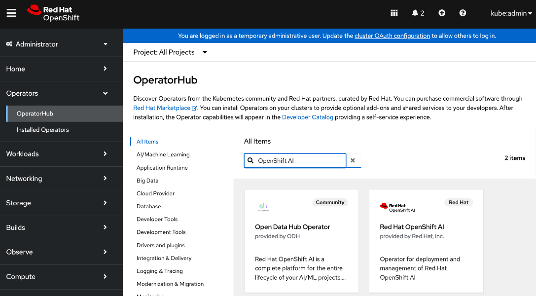
Step 3. Click the Red Hat OpenShift AI tile.
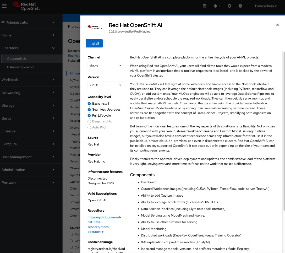
Step 4. Click Install.
Step 5. Keep the default settings. The operator will be deployed in the redhat-ods-operator namespace.
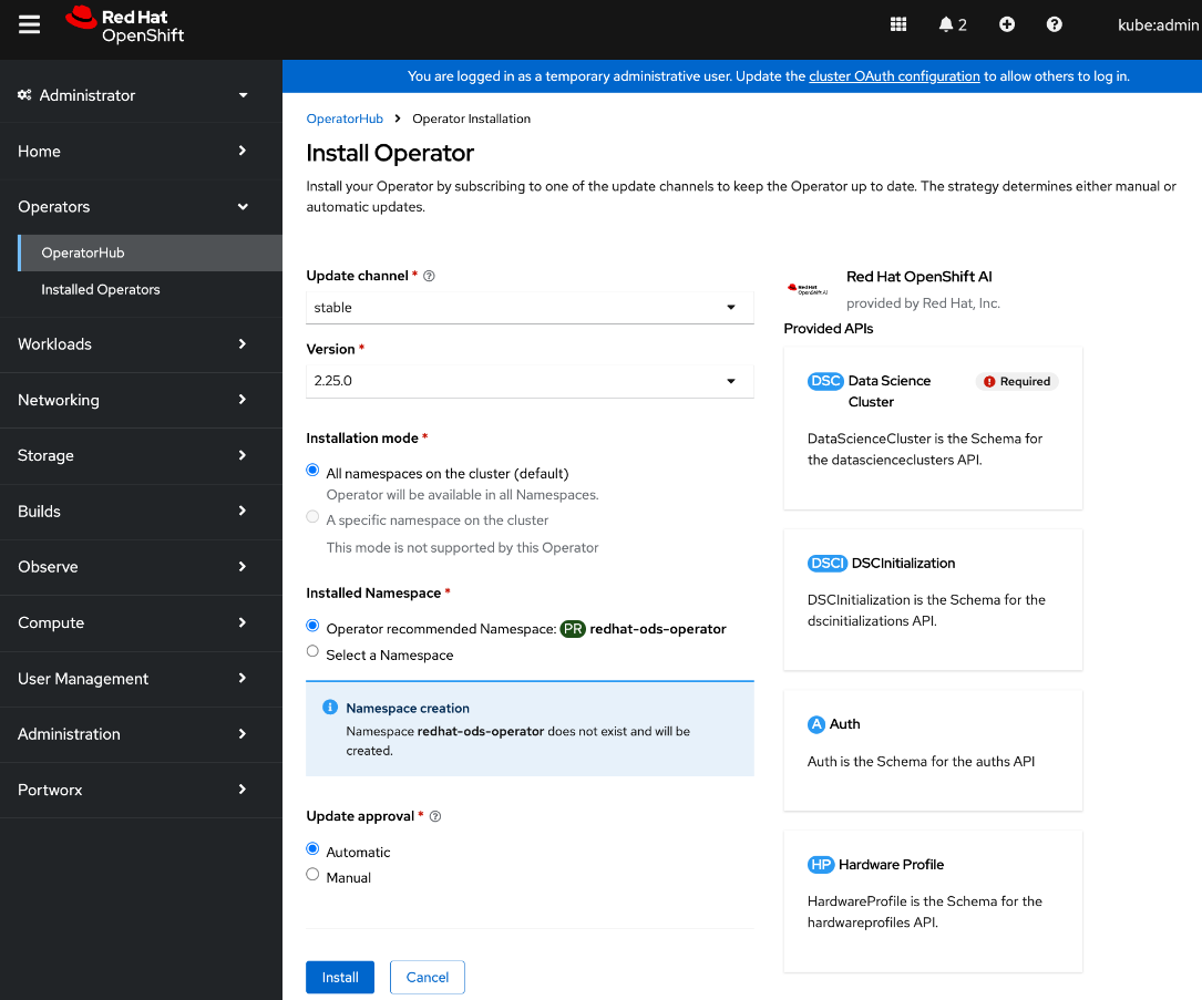
Step 6. Click Install.
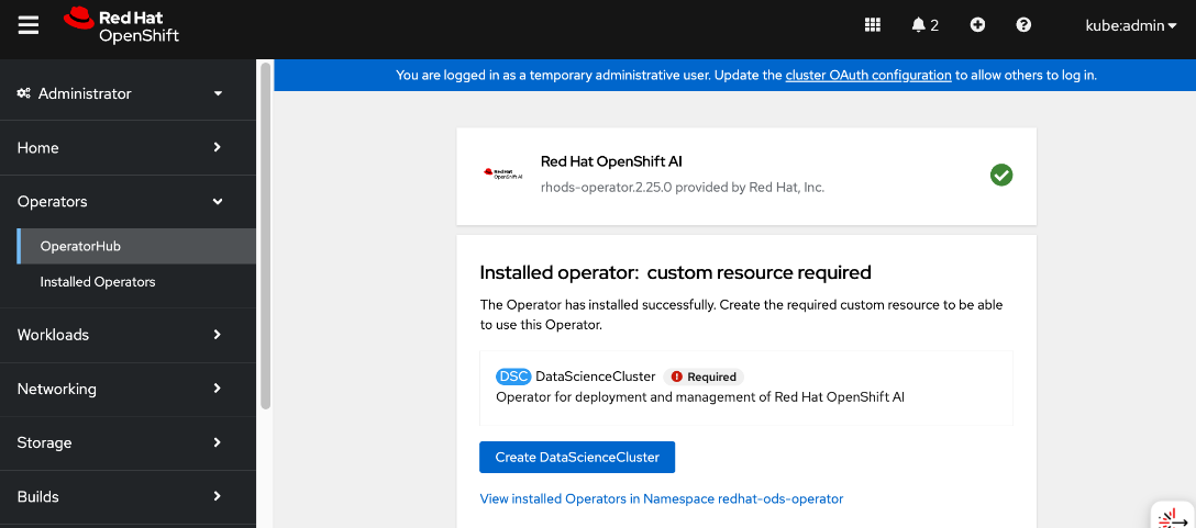
Step 7. When the installation completes, click Create DataScienceCluster.
Step 8. For Configure via:, enable the radio button for YAML view.
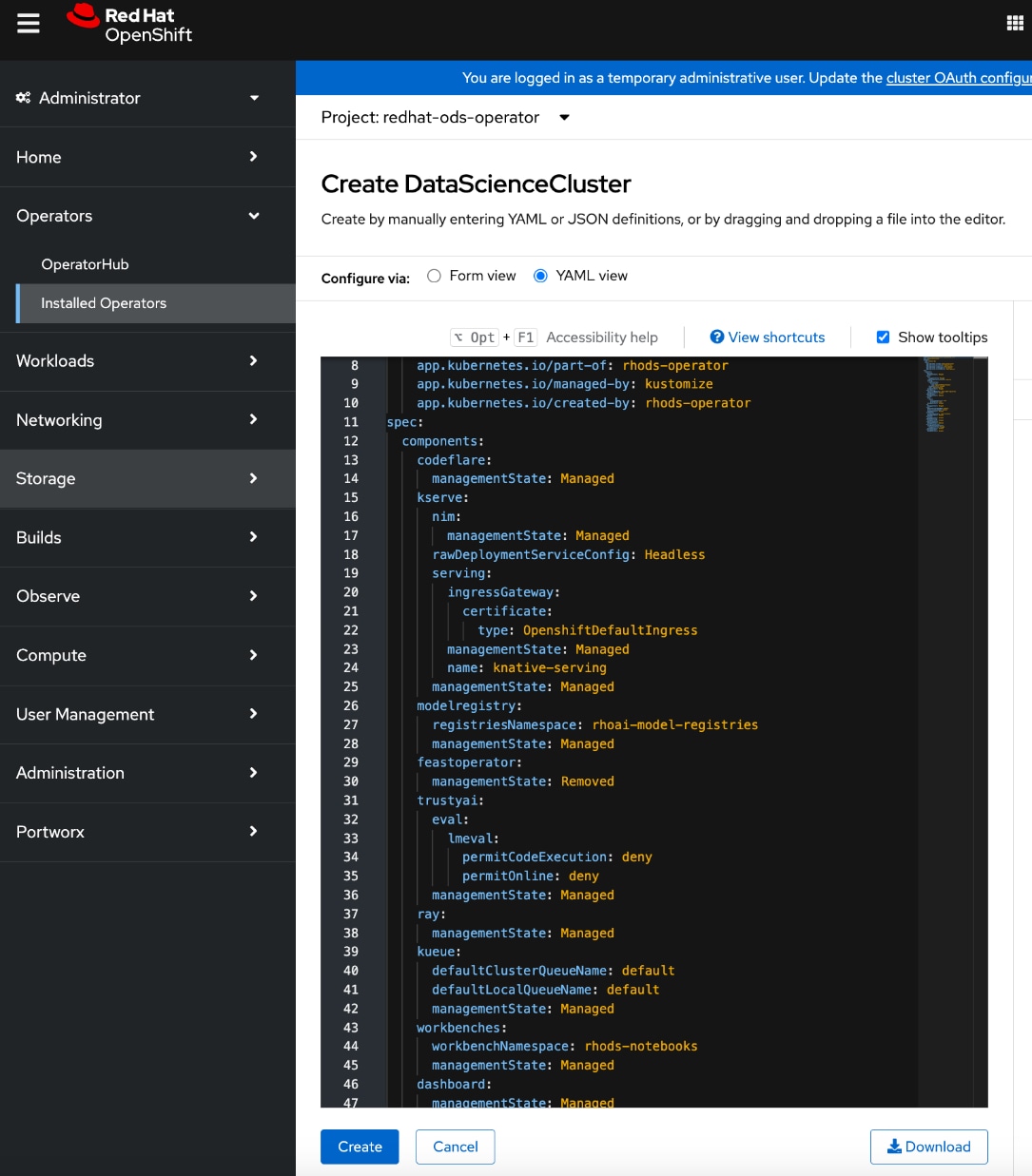
Step 9. Review the OpenShift AI components under spec > components. Verify that kserve component’s managementState is Managed.
Step 10. Click Create.
Step 11. Go to the All instances tab and verify that the default-dsc status is Ready.
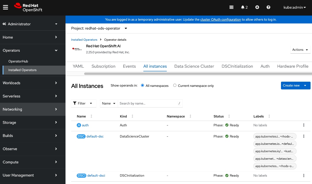
Step 12. Log into the OpenShift AI. From Red Hat OpenShift, you can click the square tile and choose Red Hat OpenShift AI from the drop-down list. You can also directly access the OpenShift AI URL (see below) – you may need to first add a DNS entry to enable this.
Step 13. Log in using a non-default admin (other than kube:admin) account. If you use the default account, you may not see the Settings menu in OpenShift AI.
Step 14. Click htpasswd if this was previously setup.

Step 15. You can now start setting up and use the environment to manage your AI/ML projects.
Set up access to S3-compatible object store
In addition to the persistent storage provided by Everpure Portworx, AI workloads often require object store(s) for various types of data generated during its lifecycle—from training and fine-tuning to production inference. In this CVD, where OpenShift AI that provides the development environment and toolsets for the AI lifecycle stages, object stores are used as mode repositories and for storing pipeline execution results.
Procedure 1. Set up access to S3-compativle object store
Step 1. Log into OpenShift AI using the direct URL or from OpenShift as outlined in the previous section.
Step 2. From the left navigation menu, go to Settings > Connection types.
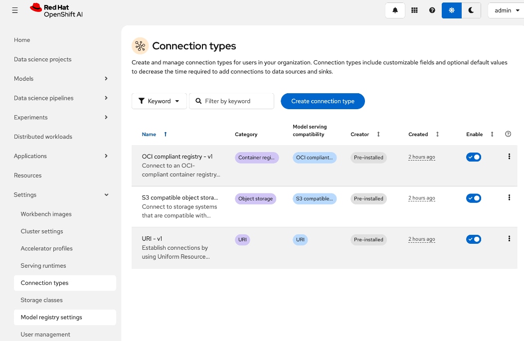
Step 3. Select the S3 compatible Object Store from the list and to duplicate, click the ellipses.
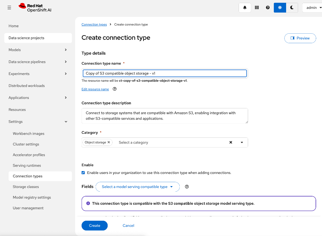
Step 4. In the Create connection type window, edit the Connection type name, and add environmental variables for the following using information from Everpure FlashBlade.
● ACCESS_KEY_ID
● SECRET_ ACCESS_KEY
● S3_ENDPOINT: Specify the S3 endpoint IP that was provisioned on Everpure FlashBlade earlier.
● S3_BUCKET: Specify a S3 bucket that was provisioned on Everpure FlashBlade earlier.
● DEFAULT_REGION: us-east-1 (could be something else).
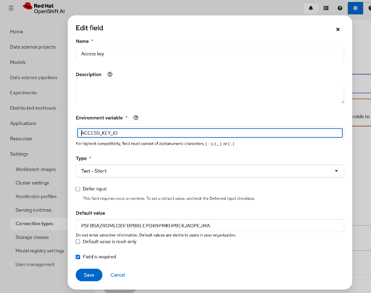
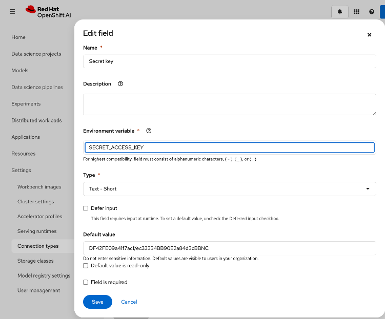
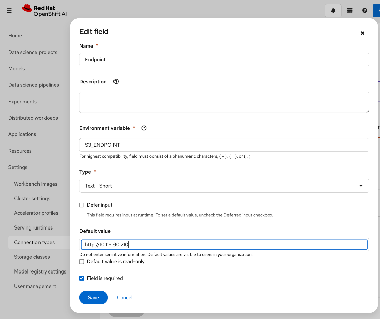
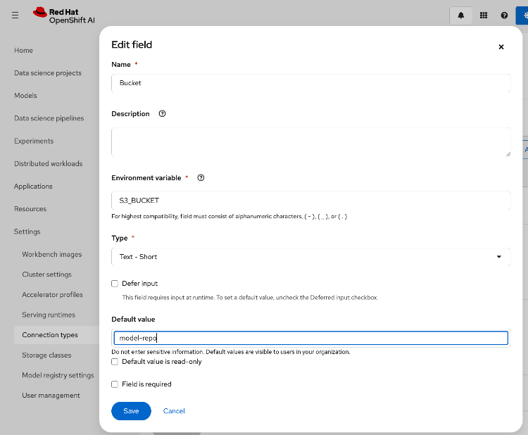
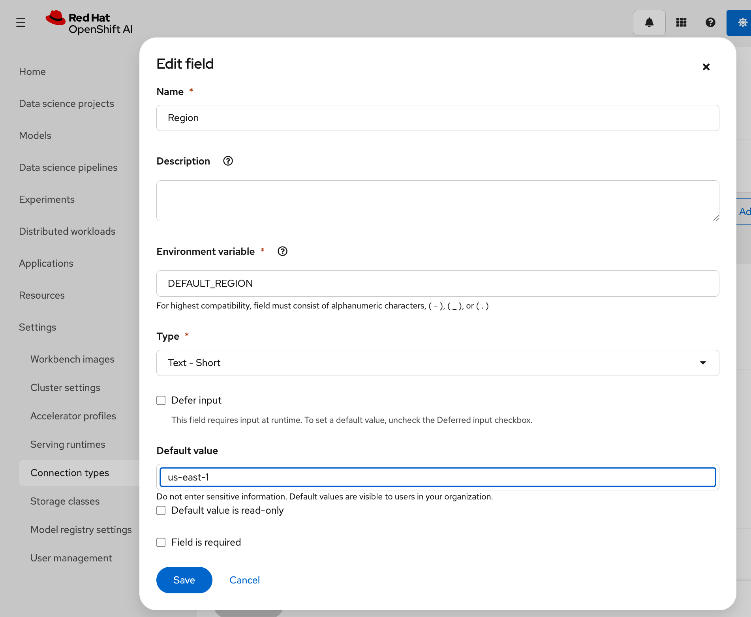
Step 5. Review the configured information.
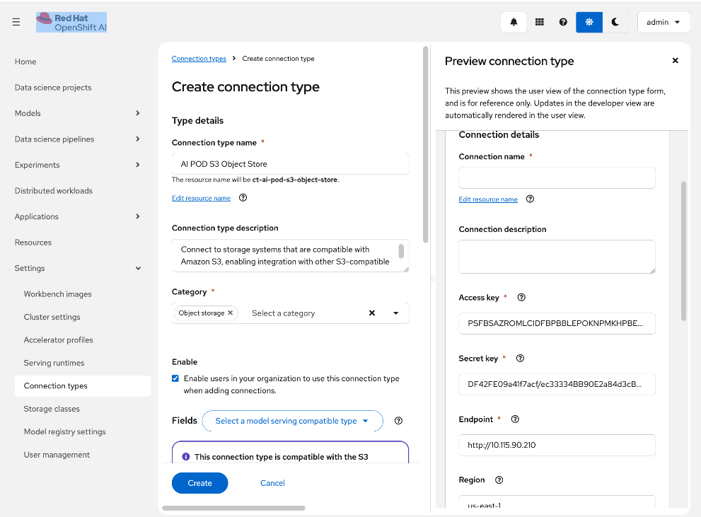
Step 6. Click Create.
Step 7. This procedure can also be done from within a specific workbench as opposed to globally.
Modify Storage Classes for Persistent Storage
AI training and fine-tuning workloads typically require ReadWriteMany access to the persistent data stores to read and write training data. The storage classes that were created in earlier section for NFS over TCP, NFS over RDMA and GPUDirect Storage are seamlessly available from within OpenShift AI. OpenShift AI administrators can modify these storage classes to enable multiple workloads, running in multiple worbenches, to have this access as detailed.
Procedure 1. Modify storage classes for persistent storage
Step 1. Log into OpenShift AI using the direct URL or from OpenShift as outlined in the previous section.
Step 2. From the left navigation menu, go to Settings > Storage classes. You can see that the previously deployed storage classes are available from withing OpenShift AI without any additional work on behalf of OpenShift or OpenShift AI administrators. However, OpenShift AI administrators can control access by disabling some, or making specific ones default from within OpenShift AI as shown below:
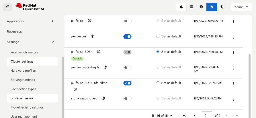
Step 3. To modify the storage class settings, select the storage class from the list and click the ellipses. Click Edit.
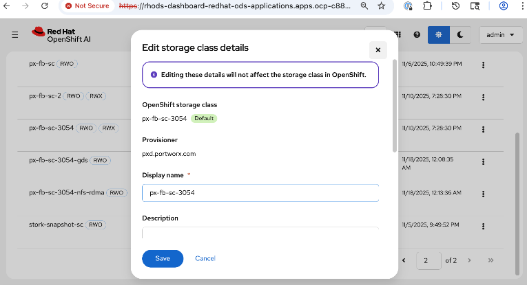
Step 4. In the Access mode enablement section, specify the access mode for the storage class as shown below:
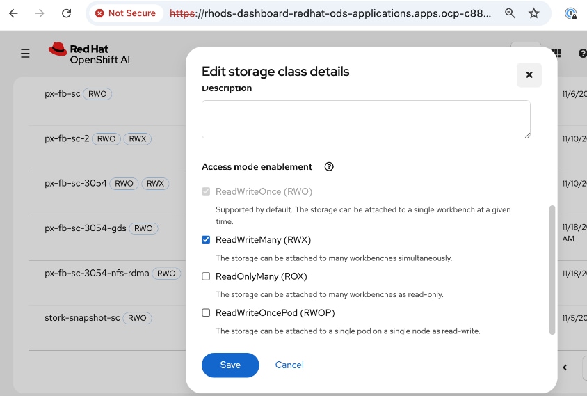
Step 5. Click Save.
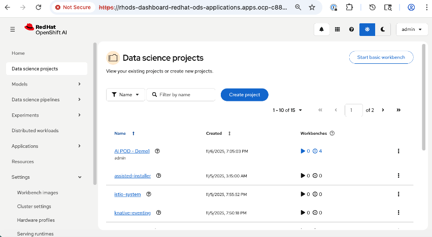
This section details the steps taken to verify the end-to-end solution in this CVD. The validation was done using OpenShift AI. The AI workload utilized multiple nodes and GPUs in the AI POD Cluster. The use case code used is available in the AI POD GitHub repo for this CVD (RHOAI folder).
Set up workbench for the workload in OpenShift AI
Procedure 1. Configure workbench for the workload in OpenShift AI
Step 1. To deploy the workload, create a project and workbench in OpenShift AI with specific resources required by the workload that will run in the workbench.
Note: For this testing, four identical workbenches were deployed.
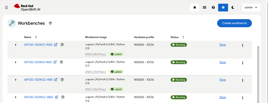
The configuration parameters for one workbench is shown below:
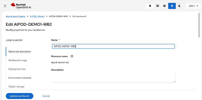
Workbench image, hardware profiles for the NVIDIA GPUs used by the workload are shown below:
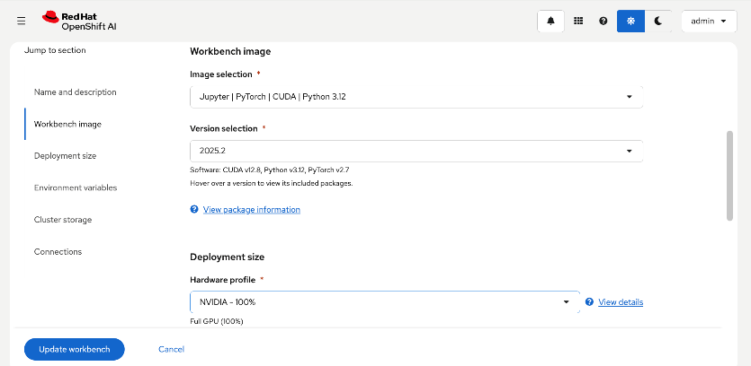
The CPU, Memory and GPU resources requested for the workload that will run in the workbench are shown below:
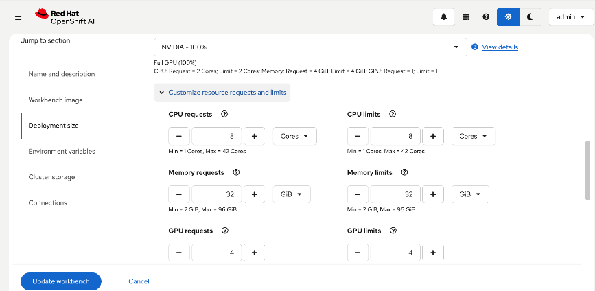
Environment variables and storage for the workload are shown below:
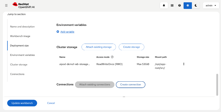
You can also select the select the storage class for the storage as shown below:
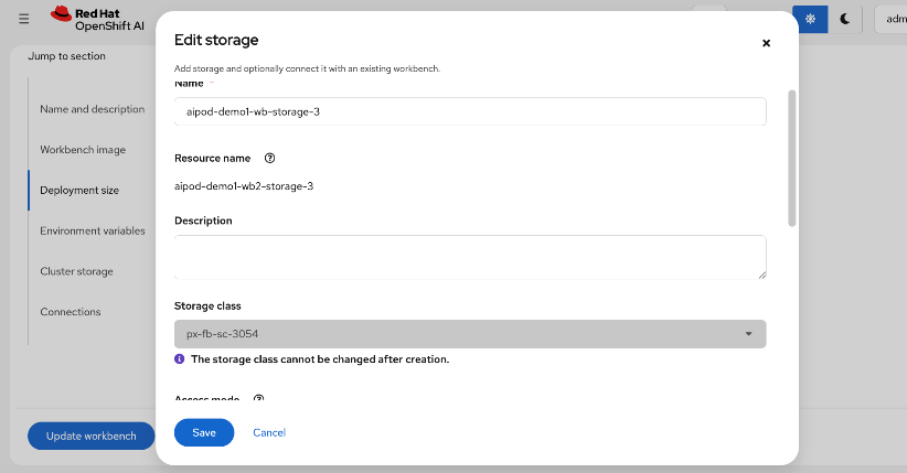
Step 2. Once the configuration is in place, click Create or Update workbench to deploy the configuration and bring up the workbench.
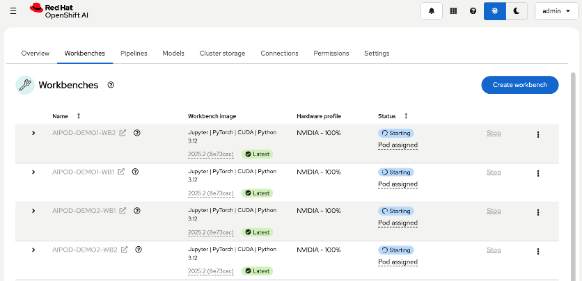
If the resources can be allocated with the specified image deployed, the workbenches will be in Running state as shown below:
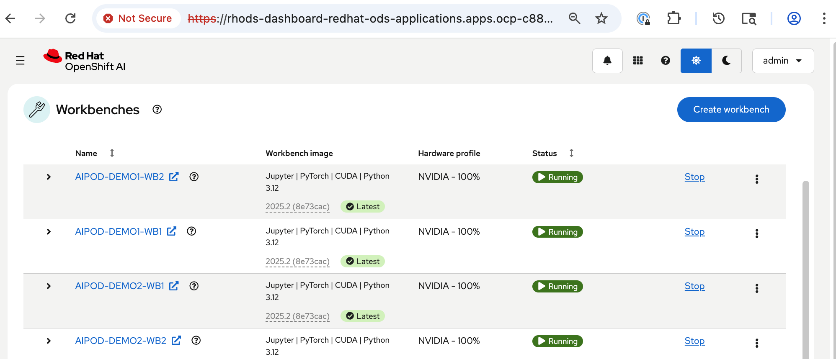
Set up Git Hub access from workbench and deploy workload
Procedure 1. Configure Git Hub access from workbench and deploy workload
Step 1. Click Running to access the workbench. Add the Github repo - see UCS Solution Repo for this CVD – OpenShift AI folder for more details.
Step 2. You can now kickoff the workload from within the workbench as shown below:
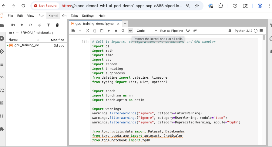
Step 3. Repeat this procedure for all workbenches. Same workload will run on all workbenches.
Monitor GPU infrastructure utilization
You can see the results from within the workbench or monitor the GPU utilization across multiple nodes as shown below:
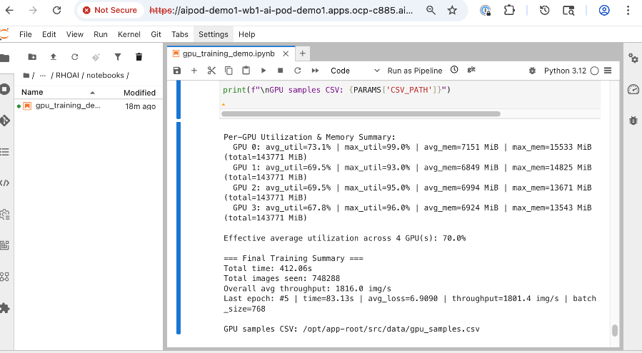
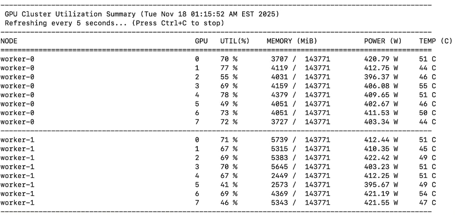
This chapter provides a summary of the validation tests, along with the hardware and software versions used to build and verify the solution in Cisco labs.
This chapter contains the following:
Hardware and Software Components Matrix
Hardware and Software Components Matrix
Table 31 lists the software versions for all the components that were used to validate the solution in Cisco labs.
Table 31. Hardware and Software Matrix
| Component (PID) |
Software/Firmware |
Notes |
|
| Backend Fabric |
|||
| Cisco Nexus 9332D-GX2B |
NXOS 10.4(5) |
Spine and Leaf switches |
|
| Frontend Fabric |
|||
| Cisco Nexus 9364D-GX2A |
NXOS 10.4(5) |
Spine switches |
|
| Cisco Nexus 9332D-GX2B |
NXOS 10.4(5) |
Compute and Storage Leaf Switches |
|
| UCS GPU Compute |
|||
| Cisco UCS C885A M8 Server |
|
|
|
| Firmware |
1.1(0.250025) |
|
|
| NVIDIA H200 GPU Driver |
570.133.20 |
Minimum version |
|
| CUDA Version |
12.8 |
Minimum version |
|
| UCS Management |
|||
| Cisco UCS X-Series Direct |
|
|
|
| Cisco UCS X9508 Chassis (UCSX-9508) |
N/A |
|
|
| Cisco UCS X Direct 100G (UCSX-S9108-100G) |
4.3(5.240162) |
|
|
| Cisco UCS X210c M7 Compute Nodes |
5.2(2.240080) |
Minimum of 3 nodes as control nodes for OpenShift or NVIDIA BCME |
|
| Cisco VIC 15231 MLOM (UCSX-ML-V5D200G) |
5.3(3.91) |
2x100G mLOM |
|
| Storage – Unified File and Object |
|||
| Everpure FlashBlade//S500 |
Purity//GB 4.6.0 |
|
|
| Everpure XFM Modules |
N/A |
|
|
| Kubernetes |
|||
| Red Hat OpenShift |
4.18.26 |
Workload Orchestration |
|
| Red Hat NFD Operator |
4.18.0-202510210939 |
|
|
| Portworx Enterprise (Operator) |
25.4.0 |
Portworx by Everpure |
|
| NVIDIA GPU Operator |
25.10.0 |
|
|
| NVIDIA Network Operator |
25.7.0 |
|
|
| Red Hat NMState Operator |
4.18.0-202510230851 |
|
|
| Red Hat OpenShift AI Operator |
2.25.0 |
Additional operators maybe required |
|
| Software, Tooling and Management |
|||
| NVIDIA AI Enterprise (NVAIE) |
7.3 |
Licenses required |
|
| Red Hat OpenShift AI |
2.25 |
MLOps Platform |
|
| Cisco Nexus Dashboard |
4.1(1)g |
3-node physical cluster |
|
| Cisco Intersight |
N/A |
SaaS platform |
|
| Splunk Observability Cloud |
N/A |
SaaS platform |
|
The interoperability matrices for the different components in the solution are provided in Table 32.
| Component |
Interoperability Matrix and Other Relevant Links |
| Cisco UCS Hardware Compatibility Matrix (HCL) |
|
| NVIDIA Licensing |
|
| NVIDIA Certification |
https://www.nvidia.com/en-us/data-center/products/certified-systems/ |
| NVIDIA AI Enterprise Qualification and Certification |
|
| NVIDIA Driver Lifecycle, Release and CUDA Support |
https://docs.nvidia.com/datacenter/tesla/drivers/index.html#lifecycle |
GPU Functional/Load Tests
The following GPU focused validation was completed:
● GPU Functional Validation – Sample CUDA Application.
● GPU Stress/Load Test using GPU Burn Tests from: https://github.com/wilicc/gpu-burn. The test iterates up to max. GPU utilization to ensure that the GPU is performing (Tflop/s) as it should before we add AI/ML workloads to Red Hat OpenShift.
The following sections provide the results of the sanity tests.
Sample CUDA Application Test
Configuration YAML file:
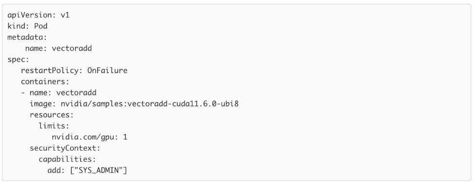
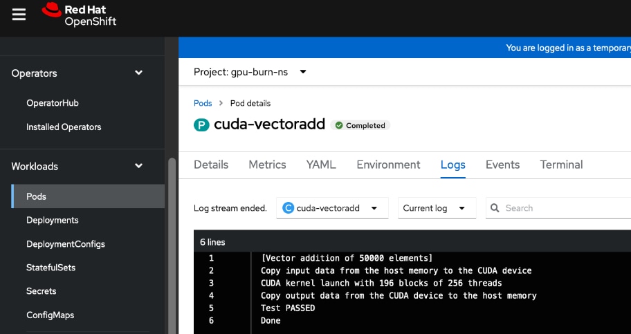
GPU Burn Test
The GPU Burn Test is used to stress testing the GPUs on the UCS C885A M8 servers in the solution. It allows for long-running load tests, ensuring that no failures occur on the GPUs even with consistent heavy load. This validates that the GPUs can handle the sustained stress levels expected during AI training. For this CVD, this test confirms the hardware stability of the Cisco UCS servers under peak utilization.
Sample results from executing the test on a Cisco UCS C885A is provided below. The test iterates up to max. GPU utilization to ensure that the GPUs are performing (Tflop/s) as it should.
Note: Before starting the test, verify that the GPUs are available and not used by any workloads.
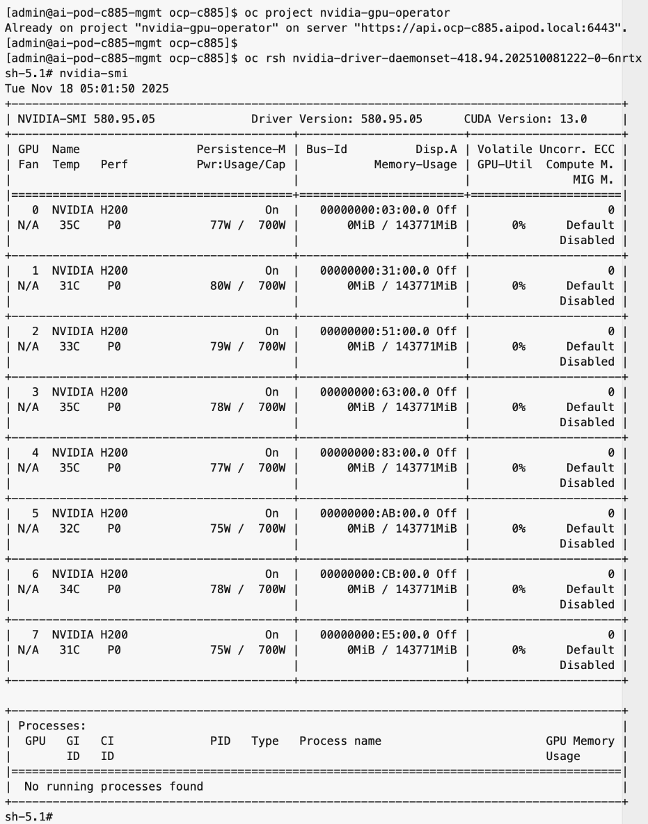
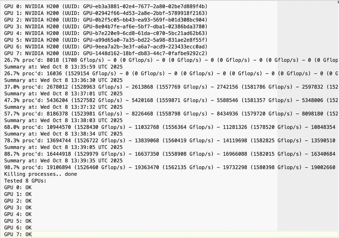
The use case code for GPU Stress/Load Test using GPU Burn Tests is available in AI POD GitHub repo. The original code is available at: https://github.com/wilicc/gpu-burn
NVIDIA Certification
Cisco provides a portfolio of NVIDIA-Certified UCS servers optimized for AI, high-performance computing (HPC), and accelerated workloads. These systems have been tested and validated for optimal performance and include the Cisco UCS C885A with H200 GPUs used in this CVD.
For a complete list of NVIDIA Certified Servers, see: https://marketplace.nvidia.com/en-us/enterprise/qualified-system-catalog/?limit=15
MLPerf Benchmarking
This section summarizes the MLPerf benchmarking tests that were executed on the UCS C885A nodes in this CVD lab setup. The results from this validation are published and available in MLCommons, in the MLPerf Training Results section. The benchmarking results for the UCS C885A M8 nodes with NVIDIA H200 SXM GPUs that were used in this AI POD setup are available here.
Test Suite Overview
The MLPerf Training benchmark suite comprises full system tests that stress models, software, and hardware for a range of machine learning (ML) applications. The open-source and peer-reviewed benchmark suite provides a level playing field for competition that drives innovation, performance, and energy efficiency for the entire industry.
The MLPerf Training v5.1 benchmark suite highlighting the rapid evolution and increasing richness of the AI ecosystem as well as significant performance improvements from new generations of systems.
Setup instructions are here: https://github.com/mlcommons/training_results_v5.1/tree/main/Cisco/benchmarks/llama2_70b_lora/implementations/nemo
Llama 2 70B-LoRA: Efficient LLM Fine-Tuning
The Llama 2 70B-LoRA utilizes the massive Llama 2 70B general LLM, fine-tuning it with Parameter-Efficient Fine-Tuning (PEFT) on the SCROLLS GovReport dataset. The primary task is high-quality document summarization, with results measured against the industry-standard ROUGE algorithm. Reflecting the trend toward complex, detailed analysis, the model is configured with a long context window of 8,192 tokens.
| Feature |
Detail |
| Model |
Llama 2 70B (70 billion parameters) |
| Method |
LoRA (Low-Rank Adaptation): This Parameter-Efficient Fine-Tuning (PEFT) technique drastically reduces training time and cost by only updating a small subset of the total parameters. |
| Task |
Document Summarization on the SCROLLS GovReport dataset, designed for instruction following and general productivity tasks. |
| Accuracy |
Performance is measured until the model reaches a target quality, evaluated using the ROUGE algorithm for summary accuracy. |
| Context |
The model utilizes a long context length of 8,192 tokens, reflecting the growing need for LLMs to process and understand lengthy documents. |
Note: Ubuntu was deployed on the UCS C885A nodes for this testing.
NCCL Tests
The NVIDIA Collective Communications Library (NCCL) provides topology-aware communication primitives to accelerate multi-GPU and multi-node training. NCCL includes both collective and point-to-point primitives, such as all-reduce, all-gather, broadcast, all-to-all, reduce, and send/receive operations. These are optimized for communication between NVIDIA GPUs within a node and across multiple nodes and are leveraged by higher-layer applications and frameworks commonly seen in AI training and fine-tuning.
NCCL tests are used to evaluate the performance of these collective operations across different types of interconnects (NVLink and RoCEv2). These low-level tests enable a quick validation that the GPUs and the end-to-end connectivity between them meet the latency and bandwidth expectations for a given collective operation within and across nodes. In this CVD, these tests confirm that the integrated solution (Cisco UCS servers, NVIDIA GPUs, and Cisco Nexus backend fabric) is functioning correctly and performing as expected.
See the Validate – GPUDirect RDMA section of this document for additional details on the NCCL tests used in this CVD to validate GPUDirect RDMA across the backend fabric.
For more information on NCCL and NCCL tests, see:
https://docs.nvidia.com/deeplearning/nccl/user-guide/docs/overview.html
https://github.com/NVIDIA/nccl-tests
IB Write Tests
The InfiniBand (IB) Write (ib_write) is another test to quickly validate that the network is performing as it should. This test uses RDMA write operations across the backend fabric to measure the bandwidth and latency. A similar test is also available for RDMA read operations across the fabric.
In this CVD, IB write tests are used to validate the RoCEv2 network performance across all paths between the nodes, via the backend NICs in Cisco UCS. These tests confirm that the back Nexus fabric Cisco Nexus fabric—provides the high-speed connectivity required for GPU-to-GPU communication across the cluster.
See the Validate – GPUDirect RDMA section of this document for additional details on the ib_write tests used in this CVD to validate RDMA writes across the backend fabric.
For more information on IB Performance Tests, see: https://github.com/linux-rdma/perftest
End-to-End Validation
Red Hat OpenShift AI is leveraged as an MLOps platforms to deploy and validate a fine-tuning workload using the GPU resources in the cluster. See the Validate End-to-End solution section of this document for additional details on the workload and testing. The use case code is provided in the AI POD GitHub repo (RHOAI folder).
Splunk Observability Cloud provides dashboards that provide end-to-end visibility to monitor the health and performance of the Cisco AI PODs infrastructure. Splunk uses OpenTelemetry Collector deployed on Red Hat OpenShift clusters and other components to ingest data into the AI POD dashboard as shown in the figure below. The dashboard can be customized as needed to monitor specific components, sub-systems or the complete solution as needed.
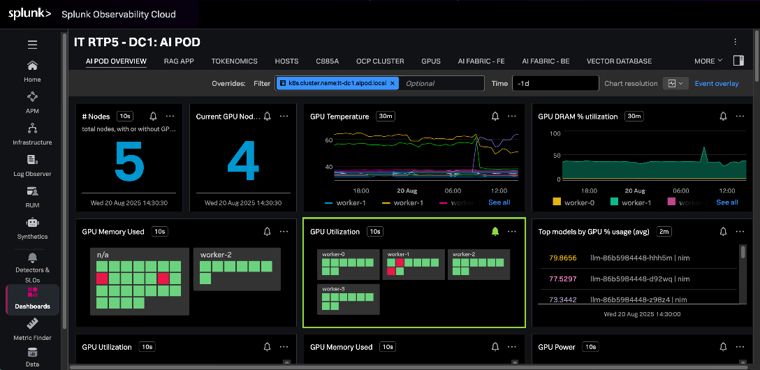
For more information, see:
https://github.com/signalfx/splunk-opentelemetry-examples/tree/main/collector/cisco-ai-ready-pods
The AI POD GitHub repository provides configurations, validated use case code, scripts and other useful tips and information, and is accessible here: https://github.com/ucs-compute-solutions/Cisco-AI-POD
Conclusion
The Cisco AI POD is a robust, full-stack infrastructure solution designed to simplify the enterprise AI journey from initial training to production-grade inference. While the Cisco AI POD portfolio supports the entire AI/ML lifecycle, this specific Cisco Validated Design focuses on the high-performance infrastructure required for enterprise AI training and fine-tuning. Serving as a prescriptive implementation guide that complements the AI POD Design Guide, this document details the integration of Cisco UCS C885A servers with NVIDIA H200 GPUs, Cisco Nexus backend and frontend fabrics, and Everpure FlashBlade to provide the high-bandwidth, low-latency foundation necessary for AI workloads.
The architectural approach of the AI POD ensures that the environment is right-sized for current enterprise needs while utilizing modular Scale Units to enable a scale-out architecture that grows with evolving requirements. By leveraging Cisco Nexus Dashboard, Cisco Intersight, and Red Hat OpenShift, the design provides the operational simplicity required to manage complex AI pipelines. Portworx by Everpure CSI for Red Hat OpenShift provides the persistent storage required for data-intensive training phases, backed by NFS file systems on Pure FlashBlade//S systems. Red Hat OpenShift AI serves as the foundational MLOps platform that runs seamlessly on OpenShift and integrates various AI/ML tools and frameworks to simplify the overall AI lifecycle.
The validation procedures conducted in Cisco labs confirm that the integrated hardware and software stack is functioning and performing as needed to support architectural expectations and enterprise-scale AI adoption. Combined with solution-level support through Cisco TAC, this deployment provides a reliable, future-ready platform that can evolve alongside new technology trends and security requirements. By leveraging CVD, organizations can build a consistent, simple, and highly performant environment tailored for the rapid pace of AI innovation.
About the author
Archana Sharma, Principal Technical Marketing Engineer, Cisco UCS Solutions, Cisco Systems Inc.
Archana Sharma is a Principal Technical Marketing Engineer with over 30 years of experience developing solutions across a wide range of technologies, including Data Center, Desktop Virtualization, Collaboration, and other Layer 2 and Layer 3 technologies. In her current role, Archana’s focusses on the design, developing and validating Cisco UCS based AI solutions for enterprise data centers. She is the author of several Cisco Validated Designs, and a regular speaker at industry events like Cisco Live. Archana holds a CCIE (#3080) in routing and switching and a bachelor’s degree in electrical engineering from North Carolina State University.
Acknowledgements
For their support and contribution to the design, validation, and creation of this Cisco Validated Design, the author would like to thank:
Red Hat Team
● Ben Schmaus, Senior Principal Software Engineer, Red Hat
● Hemang Shishir, Principal Specialist AI Architect, Red Hat
● Stephen Malkinson, Principal Solution Architect, Red Hat
Cisco Team
● Ramesh Isaac, Technical Marketing Engineer, Cisco UCS Solutions
● John George, Technical Marketing Engineer, Cisco UCS Solutions
● Anil Dhiman Technical Marketing Engineer, Cisco UCS Solutions
● Marina Ferreira, Principal Solutions Engineer, Cisco Sales
● Weiguo Sun, Principal Engineer, Cisco IT
● Chris Baldwin, Technical Systems Architect, Cisco IT
● Mohammed A Jameel, Network Systems Engineering Technical Leader, Cisco IT
● Nikhil Mitra, SRE Technical Leader, Cisco IT
● Kevin Marschalk, Program Manager, Cisco IT
● Gurudatt Katakdhond, Technical Program Manager, Cisco IT
● Louis Watta, Director, Software Engineering, Cisco IT
● Chris O’Brien, Senior Director, Technical Marketing, Cisco UCS Solutions
Everpure Team
● Yogesh Ramdoss, Solutions Engineer, Everpure
● Vijay Bhaskar Kulari, Senior Technical Marketing Engineer, Everpure
● Shiva Kumar J R, Senior Program Manager, Everpure
● Philip Ninan, Solutions Director, Everpure
● Craig Waters, Solutions Director, Everpure
Appendix
This appendix contains the following:
AI POD Solutions
Design Zone for AI Ready Infrastructure: https://www.cisco.com/c/en/us/solutions/design-zone/ai-ready-infrastructure.html
GitHub Repo for Cisco UCS Solutions: https://github.com/ucs-compute-solutions
Backend Fabric
General
Evolve your AI/ML Network with Cisco Silicon One: https://www.cisco.com/c/en/us/solutions/collateral/silicon-one/evolve-ai-ml-network-silicon-one.html
Doubling all2all Performance with NVIDIA Collective Communication Library 2.12: https://developer.nvidia.com/blog/doubling-all2all-performance-with-nvidia-collective-communication-library-2-12/
Cisco Massively Scalable Data Center Network Fabric Design and Operation White Paper: https://www.cisco.com/c/en/us/products/collateral/switches/nexus-9000-series-switches/white-paper-c11-743245.html
QoS References
Network Best Practices for Artificial Intelligence Data Center: https://www.ciscolive.com/c/dam/r/ciscolive/emea/docs/2025/pdf/BRKDCN-2921.pdf
Cisco Data Center Networking Blueprint for AI/ML Applications: https://www.cisco.com/c/en/us/td/docs/dcn/whitepapers/cisco-data-center-networking-blueprint-for-ai-ml-applications.html
RoCE Storage Implementation over NX-OS VXLAN Fabrics: https://www.cisco.com/c/en/us/td/docs/dcn/whitepapers/roce-storage-implementation-over-nxos-vxlan-fabrics.html
Load Balancing References
Nexus Improves Load Balancing and Brings UEC Closer to Adoption (Blog): https://blogs.cisco.com/datacenter/nexus-improves-load-balancing-and-brings-uec-closer-to-adoption
Cisco AI Networking for Data Center with NVIDIA Spectrum-X Solution Overview: https://www.cisco.com/c/en/us/products/collateral/networking/cloud-networking-switches/nexus-9000-switches/ai-networking-dc-nvidia-spectrum-x-so.html
Meet Cisco Intelligent Packet Flow: https://www.cisco.com/c/en/us/products/collateral/ios-nx-os-software/nx-os-software/intelligent-packet-flow-solution-overview.html
Cisco Nexus 9000 Series NX-OS Unicast Routing Configuration Guide, Release 10.5(x): https://www.cisco.com/c/en/us/td/docs/dcn/nx-os/nexus9000/105x/unicast-routing-configuration/cisco-nexus-9000-series-nx-os-unicast-routing-configuration-guide/m-configure-dynamic-load-balancing.html
AI-Ready Infrastructure: A New Era of Data Center Design: https://blogs.cisco.com/datacenter/ai-ready-infrastructure-a-new-era-of-data-center-design
Why Cisco Nexus 9000 with Nexus Dashboard for AI Networking White Paper: https://www.cisco.com/c/en/us/products/collateral/networking/cloud-networking-switches/nexus-9000-switches/nexus-9000-ai-networking-wp.html
Cisco Nexus 9000 Series Switches for AI Clusters White Paper with Performance Validation Insights: https://www.cisco.com/c/en/us/products/collateral/switches/nexus-9000-series-switches/nexus-9000-series-switches-ai-clusters-wp.html
NVIDIA
(PXN) Doubling all2all Performance with NVIDIA Collective Communication Library 2.12: https://developer.nvidia.com/blog/doubling-all2all-performance-with-nvidia-collective-communication-library-2-12/
NVIDIA Collective Communications Library (NCCL): https://developer.nvidia.com/nccl
NVIDIA Enterprise Reference Architecture (NVIDIA does not provide links that can be shared. However, the exact titles are provided below. Cisco has access to these using NVIDIA’s Partner Portal:
● ERA-00003-001_v04 - NVIDIA HGX H100+H200+B200 8-GPU and NVIDIA Spectrum Platforms - 28th February 2025
● ERA-00010-001_v01 - Network Deployment Guide NVIDIA SpectrumX Platforms - 4th July 2025 (2)
GPUDirect: https://developer.nvidia.com/gpudirect
GPUDirect RDMA: https://docs.nvidia.cn/cuda/gpudirect-rdma/index.html#supported-systems
GPUDirect Storage: https://docs.nvidia.com/gpudirect-storage/index.html
Network Operator: https://docs.nvidia.com/networking/display/kubernetes25100/advanced/doca-drivers.html#example-of-nicclusterpolicy
Splunk
Unlocking AI Performance: Splunk Observability for Cisco Secure AI Factory with NVIDIA: https://blogs.cisco.com/datacenter/unlocking-ai-performance-splunk-observability-for-cisco-secure-ai-factory-with-nvidia
Security
Cisco AI Defense: https://www.cisco.com/site/us/en/products/security/ai-defense/index.html
AI Defense on Cisco AI PODs Reference Architecture: https://www.cisco.com/c/en/us/td/docs/unified_computing/ucs/UCS_CVDs/AI_defense_on_Cisco_AI_PODs_reference_architecture.html
Cisco UCS AI Servers
Cisco UCS Hardware Compatibility List (HCL) Tool: https://ucshcltool.cloudapps.cisco.com/public/
Cisco’s Transceiver Matrix Group:
Cisco UCS C885A M8 Server
Cisco UCS C845A M8 Server: https://www.cisco.com/c/dam/en/us/products/collateral/servers-unified-computing/ucs-c-series-rack-servers/ucs-c845a-m8-rack-server-spec-sheet.pdf
Cisco UCS C885A M8 Data Sheet: https://www.cisco.com/c/en/us/products/collateral/servers-unified-computing/ucs-c-series-rack-servers/ucs-c885a-m8-ds.html
Cisco UCS C885A M8 Spec Sheet: https://www.cisco.com/c/dam/en/us/products/collateral/servers-unified-computing/ucs-c-series-rack-servers/ucs-c885a-m8-rack-server-spec-sheet.pdf
Cisco UCS C885A M8 Server Installation and Service Guide: https://www.cisco.com/c/en/us/support/servers-unified-computing/ucs-c-series-rack-servers/products-installation-guides-list.html
Cisco UCS C885A M8 At-a-Glance: https://www.cisco.com/c/en/us/products/collateral/servers-unified-computing/ucs-c-series-rack-servers/ucs-c885a-m8-aag.html
Cisco UCS C845A M8 Server
Cisco UCS C845A M8 Rack Server Data Sheet: https://www.cisco.com/c/en/us/products/collateral/servers-unified-computing/ucs-c-series-rack-servers/ucs-c845a-m8-rack-server-ds.html
Cisco UCS C845A M8 AI Server Spec Sheet: https://www.cisco.com/c/dam/en/us/products/collateral/servers-unified-computing/ucs-c-series-rack-servers/ucs-c845a-m8-rack-server-spec-sheet.pdf
Cisco UCS C845A M8 AI Servers Memory Guide: https://www.cisco.com/c/dam/en/us/products/collateral/servers-unified-computing/ucs-c-series-rack-servers/ucs-c845Am8-memory-guide.pdf
Cisco UCS C845A M8 Rack Server At a Glance: https://www.cisco.com/c/en/us/products/collateral/servers-unified-computing/ucs-c-series-rack-servers/ucs-c845a-m8-rack-server-aag.html
Cisco UCS C880A M8 Server
Cisco UCS C880A M8 Rack Server Data Sheet: https://www.cisco.com/c/en/us/products/collateral/servers-unified-computing/ucs-c-series-rack-servers/ucs-c880a-m8-rack-server-ds.html
Cisco UCS C880A M8 Rack Server Spec Sheet: https://www.cisco.com/c/dam/en/us/products/collateral/servers-unified-computing/ucs-c-series-rack-servers/ucs-c880a-m8-rack-server-spec-sheet.pdf
Cisco Nexus Switches
Cisco Nexus 9332D-GX2B and Nexus 9364D-GX2A Switch Data Sheet: https://www.cisco.com/site/us/en/products/collateral/networking/switches/nexus-9000-series-switches/nexus-9300-gx2-series-fixed-switches-data-sheet.html#tabs-35d568e0ff-item-4bd7dc8124-tab
Cisco Nexus 9364E-SG2 Switch Data Sheet: https://www.cisco.com/c/en/us/products/collateral/switches/nexus-9000-series-switches/nexus-9364e-sg2-switch-ds.html
Cisco Nexus Dashboard 4.1: Data Center Management for the AI Era - Cisco Blogs: https://blogs.cisco.com/datacenter/announcing-the-new-nexus-dashboard-for-simplifying-data-center-operations-in-the-ai-era
Cisco Nexus Dashboard 4.1.1 Release notes: https://www.cisco.com/c/en/us/td/docs/dcn/nd/4x/release-notes/cisco-nexus-dashboard-release-notes-411.html
Cisco Nexus Dashboard Data Sheet: https://www.cisco.com/c/en/us/products/collateral/data-center-analytics/nexus-dashboard/datasheet-c78-744371.html
Cisco Data Center Networking (DCN) Licensing Ordering Guide: https://www.cisco.com/c/en/us/products/collateral/data-center-analytics/nexus-dashboard/guide-c07-744361.html
(Internal) Cisco Nexus Dashboard 4.1 release updates - Seller Guide: https://salesconnect.seismic.com/Link/Content/DCb3d1cbc5-fb94-4583-86fe-c64261203275
(Internal) EMEA Cloud & AI Infrastructure PVT May 2025 - Exploring the Nexus Dashboard 4.x releases – PDF: https://salesconnect.seismic.com/Link/Content/DC7cce6697-d173-4ddf-892c-3d6813a17816
Everpure
Everpure: https://www.purestorage.com/
Everpure FlashBlade: https://www.purestorage.com/products/unstructured-data-storage.html
Portworx by Everpure: https://www.purestorage.com/products/cloud-native-applications/portworx.html
FlashStack: https://www.purestorage.com/products/integrated-platforms/flashstack.html
Red Hat OpenShift
Red Hat OpenShift Operators: https://www.redhat.com/en/technologies/cloud-computing/openshift/what-are-openshift-operators
Red Hat OpenShift Ecosystem catalog: https://catalog.redhat.com/software/search?deployed_as=Operator
NVIDIA Tools Repo: https://github.com/schmaustech/nvidia-tools-image
Red Hat OpenShift AI
https://www.redhat.com/en/products/ai/openshift-ai
https://ai-on-openshift.io/getting-started/openshift-ai/
CVD Program
ALL DESIGNS, SPECIFICATIONS, STATEMENTS, INFORMATION, AND RECOMMENDATIONS (COLLECTIVELY, "DESIGNS") IN THIS MANUAL ARE PRESENTED "AS IS," WITH ALL FAULTS. CISCO AND ITS SUPPLIERS DISCLAIM ALL WARRANTIES, INCLUDING, WITHOUT LIMITATION, THE WARRANTY OF MERCHANTABILITY, FITNESS FOR A PARTICULAR PURPOSE AND NONINFRINGEMENT OR ARISING FROM A COURSE OF DEALING, USAGE, OR TRADE PRACTICE. IN NO EVENT SHALL CISCO OR ITS SUPPLIERS BE LIABLE FOR ANY INDIRECT, SPECIAL, CONSEQUENTIAL, OR INCIDENTAL DAMAGES, INCLUDING, WITHOUT LIMITATION, LOST PROFITS OR LOSS OR DAMAGE TO DATA ARISING OUT OF THE USE OR INABILITY TO USE THE DESIGNS, EVEN IF CISCO OR ITS SUPPLIERS HAVE BEEN ADVISED OF THE POSSIBILITY OF SUCH DAMAGES.
THE DESIGNS ARE SUBJECT TO CHANGE WITHOUT NOTICE. USERS ARE SOLELY RESPONSIBLE FOR THEIR APPLICATION OF THE DESIGNS. THE DESIGNS DO NOT CONSTITUTE THE TECHNICAL OR OTHER PROFESSIONAL ADVICE OF CISCO, ITS SUPPLIERS OR PARTNERS. USERS SHOULD CONSULT THEIR OWN TECHNICAL ADVISORS BEFORE IMPLEMENTING THE DESIGNS. RESULTS MAY VARY DEPENDING ON FACTORS NOT TESTED BY CISCO.
CCDE, CCENT, Cisco Eos, Cisco Lumin, Cisco Nexus, Cisco StadiumVision, Cisco TelePresence, Cisco WebEx, the Cisco logo, DCE, and Welcome to the Human Network are trademarks; Changing the Way We Work, Live, Play, and Learn and Cisco Store are service marks; and Access Registrar, Aironet, AsyncOS, Bringing the Meeting To You, Catalyst, CCDA, CCDP, CCIE, CCIP, CCNA, CCNP, CCSP, CCVP, Cisco, the Cisco Certified Internetwork Expert logo, Cisco IOS, Cisco Press, Cisco Systems, Cisco Systems Capital, the Cisco Systems logo, Cisco Unified Computing System (Cisco UCS), Cisco UCS B-Series Blade Servers, Cisco UCS C-Series Rack Servers, Cisco UCS S-Series Storage Servers, Cisco UCS X-Series, Cisco UCS Manager, Cisco UCS Management Software, Cisco Unified Fabric, Cisco Application Centric Infrastructure, Cisco Nexus 9000 Series, Cisco Nexus 7000 Series. Cisco Prime Data Center Network Manager, Cisco NX-OS Software, Cisco MDS Series, Cisco Unity, Collaboration Without Limitation, EtherFast, EtherSwitch, Event Center, Fast Step, Follow Me Browsing, FormShare, GigaDrive, HomeLink, Internet Quotient, IOS, iPhone, iQuick Study, LightStream, Linksys, MediaTone, MeetingPlace, MeetingPlace Chime Sound, MGX, Networkers, Networking Academy, Network Registrar, PCNow, PIX, PowerPanels, ProConnect, ScriptShare, SenderBase, SMARTnet, Spectrum Expert, StackWise, The Fastest Way to Increase Your Internet Quotient, TransPath, WebEx, and the WebEx logo are registered trade-marks of Cisco Systems, Inc. and/or its affiliates in the United States and certain other countries. (LDW_P5)
All other trademarks mentioned in this document or website are the property of their respective owners. The use of the word partner does not imply a partnership relationship between Cisco and any other company. (0809R)