RoCE Storage Implementation over NX-OS VXLAN Fabrics
Available Languages
Bias-Free Language
The documentation set for this product strives to use bias-free language. For the purposes of this documentation set, bias-free is defined as language that does not imply discrimination based on age, disability, gender, racial identity, ethnic identity, sexual orientation, socioeconomic status, and intersectionality. Exceptions may be present in the documentation due to language that is hardcoded in the user interfaces of the product software, language used based on RFP documentation, or language that is used by a referenced third-party product. Learn more about how Cisco is using Inclusive Language.
- US/Canada 800-553-2447
- Worldwide Support Phone Numbers
- All Tools
 Feedback
 Feedback
Summary
The advent of Remote Direct Memory Access (RDMA) over converged ethernet on a hyper scale data center challenges DC network operator- to provide a low latency, lossless fabric at par with InfiniBand fabrics. Though lossless and low latency behavior can be achieved by allocating required network resources, those network resources are shared across other data center applications. The intent of this writing is to understand and configure RoCEv2 storage traffic to achieve lossless behavior over a VXLAN multi-site fabric.
Though this deployment guide describes the details of ROCE over VXLAN Multi-Site, one must be cautious about the geographic locations where VXLAN sites are deployed. We recommend that VXLAN sites are used only where the Data Center is spread over campuses or the same buildings. This helps achieve lossless converged ethernet constraints for ROCE traffic. This document provides details about multi-VXLAN and RoCE deployment.
To make the best decision, you should know the acceptable latency or RTT of the applications that are riding on the fabric. So, communication end nodes [Hosts or Targets] must be in proximity although they are deployed over Multi-Site VXLAN fabric.
This document covers,
1. RoCEv2 basics
2. Multi-Site VXLAN fabric and packet flow over the fabric
3. PFC and achieving lossless behavior with PFC
4. ECN and achieving lossless behavior on VXLAN fabric
5. Generating ECNs using WRED and Cisco’s AFD QoS configs
Introduction
Non-Volatile Memory Express (NVMe) allows hosts to fully exploit the levels of parallelism possible with modern SSDs. As a result, NVMe reduces the I/O overhead and brings performance improvements relative to previous logical-device interfaces, including multiple long command queues, and reduced latency. SCSI and other previous interface protocols were developed for use with slower hard disk drives where a lengthy delay, relative to CPU operations, exists between a request and data transfer, where data speeds are slower than RAM speeds, and where disk rotation and seek time that is led to further optimization requirements.
NVMe over Fabrics (NVMe-oF)
The NVMe protocol is more than just connecting a local flash drive inside a server, it may also be used over a network. When used in this context, a network “fabric” enables any-to-any connections among storage and server elements. NVMe over Fabrics (NVMe-oF) enables a high-performance storage network with latency that rivals direct attached storage. As a result, fast storage devices can be shared.
NVMe/RDMA – Supported on InfiniBand or Ethernet networks
An InfiniBand (IB) architecture provides credit-based flow control for lossless, TCP/IP bypass, RDMA, and zero-copy. The first version of RDMA over Converged Ethernet (RoCE), supports zero-copy like InfiniBand by enabling the hardware network adapter to copy the data directly from the application memory. To maintain a reliable connection, the destination Queue Pair (QP) maintains the packet flow using the sequence number in the IB Base Transport Header (BTH). As there is no IP information on RoCEv1, the lossless behavior can only be achieved using Priority Flow Control (PFC) in the network.
What is RDMA?
Direct Memory Access (DMA) is the ability of a device to access host memory directly, without the intervention of the CPU. Remote Direct Memory Access (RDMA) is the ability to access (read and write) memory on a remote machine without interrupting CPU operations.
RDMA Main Advantages
● Zero-copy – Applications can perform data transfers without engaging the network software stack. Data is sent and received directly to the buffers without being copied between the network layers.
● Kernel bypass – Applications can perform data transfers directly from user-space without kernel involvement
● No CPU involvement – Applications can access remote memory without consuming any CPU time in the remote server. The remote memory server will be read without any intervention from the remote process (or processor). Moreover, the caches of the remote CPU will not be filled with the accessed memory content
What is RoCE?
RDMA over Converged Ethernet (RoCE – pronounced “Rocky”) is a network protocol that allows Remote Direct Memory Access (RDMA) over an Ethernet network. It does this by encapsulation of an InfiniBand transport packet over Ethernet. There are two versions of RoCE:
● RoCEv1 – Ethernet link layer protocol (Ethertype 0x8915) allows communication between two hosts in the same Ethernet broadcast domain. So, layer-2 only that is not routable.
● RoCEv2 – Enhances RoCEv1 with a UDP/IP (IPv4 or IPv6) header and adds layer-3 routability. RoCEv2 is also known as Routable RoCE.

Later, RoCE is carried over IP and UDP which leads to RoCEv2. The UDP destination port-4791 indicates that the payload is an InfiniBand payload with InfiniBand Base Transport header. RoCEv2 can use different source UDP ports for different QPs that help ECMP load sharing. RoCEv2 is used on an IP fabric where the lossless nature is achieved using Priority Flow Control (PFC) or using Explicit Congestion Notification (ECN) on a lossy IP fabric.
RoCEv2 on a lossy IP fabric is called Resilient RoCE, uses ECN bits on the IP header to achieve lossless behavior during congestion in the network.

On a storage network, we have servers that do read or write operations with a storage device. The servers are referred to as Initiators and the storage devices are called Targets.
How to support RoCEv2 on the network
A RoCEv2 network fabric should use various intelligent congestion control technologies to eliminate the potential packet loss and high latency of a traditional Ethernet network. The goal is to have zero-packet-loss, low-latency, and high-throughput network for RoCEv2 distributed applications, meeting the stringent performance requirements of these applications
The benefits of introducing RoCE in data center infrastructure include:
● Lower cost of ownership because a separate storage networking infrastructure is not needed.
● Higher ROI across traditional and modern agile infrastructures.
● Improved overall CPU utilization for using applications.
● Efficient host memory usage.
● Higher throughput and lower latency for computing and storage traffic.
In our case study with VXLAN Multi-Site Fabric, the lossless behavior is achieved using Priority Flow Control (PFC) and Explicit Congestion Notification (ECN).
Priority Flow Control (PFC)
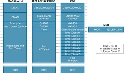
PFC, which is also referred to as Class-based Flow Control (CBFC) or Per Priority Pause (PPP), is a mechanism that prevents frame loss caused due to congestion. PFC is like 802.3x Flow Control (pause frames) or link-level flow control (LFC). However, PFC functions on a per class-of-service (CoS) basis: When a buffer threshold is exceeded due to congestion, 802.3x flow control or LFC sends a pause frame to its peer to pause all data transmission on the link for a specified period. When the congestion is mitigated, when traffic comes under the configured threshold, a resume frame is generated to restart data transmission on the link.
In contrast, during congestion, PFC sends a pause frame that indicates which CoS value needs to be paused. A PFC pause frame contains a 2-octet timer value for each CoS that indicates the length of time that the traffic must be paused. The unit of time for the timer is specified in pause quanta. A quanta is the time required for transmitting 512 bits at the speed of the port. The range is from 0 to 65535. A pause frame with a pause quanta of 0 indicates a resume frame to restart the paused traffic. PFC asks the peer to stop sending frames of a particular CoS value by sending a pause frame to a well-known multicast address. This pause frame is a one-hop frame that is not forwarded when received by the peer. When the congestion is mitigated, PFC can request the peer to restart transmitting frames
 |
PFC Storm
A malfunctioning NIC on a host may not be able to receive any traffic from the network and continues sending PFC pause frames towards the switch. Lossless switch paths do not drop packets but decline to receive more packets when their buffers fill up. If the end-port queue is stuck for a long time, the buffers fill up not only for the target switch but also on all switches with problematic port queues in the traffic forwarding path. This leads to endless PFC pause frames, also called a PFC storm, being observed on all switch ports along the path to the traffic source.
PFC Watchdog (PFCWD) on Nexus 9000 Series Switches
To mitigate this, the PFC watchdog can be used on the Nexus switches to prevent congestion. When the switches detect this situation on any egress queue, all the packets in the queue are flushed, and new packets that are destined to the same queue are dropped as well until PFC storming is relieved. We lose some packets with this solution, but only temporarily. Without this mechanism, the traffic of this queue is blocked all along the path, until the faulty NIC is restarted or replaced.
Explicit Congestion Notification (ECN)
ECN is a notification mechanism on the packet forwarding direction which marks packets instead of dropping on a WRED-enabled queue when the average queue length exceeds a specific threshold value. When configured with the WRED ECN feature, the Nexus 9k switches mark the ECN bit at the point of congestion. The end hosts’ application on seeing the ECN bit enabled packets ask the source traffic to slow down by an application-specific slow down mechanism.
In case of congestion, the network device marks the packet with ECN Congestion Encountered bit to (0x11). This ECN flag set packet arrives at the destination and the destination sends a notification to the sender to reduce the traffic rate.
ECN uses the two least significant (right-most) bits of the Traffic Class field in the IPv4 or IPv6 header to encode four different code points:
0x00 – Non-ECN-Capable Transport (Non-ECT)
0x10 – ECN Capable Transport 0 (ECT-0)
0x01 – ECN Capable Transport 1 (ECT-1)
0x11 – Congestion Encountered (CE)
Using PFC and ECN together
For optimal RDMA performance in rapidly changing and dynamic network environments, both PFC and ECN can be used together. In that case, congestion caused by traffic patterns such as in-cast can be easily mitigated with ECN, because capabilities that exist anywhere in the data path congestion are signaled to the endpoints. However, if congestion is experienced close to the endpoints and caused by a bursty application by the sender, PFC efficiently mitigates and manages the congestion by slowing down the traffic rate from the sender. In summary, ECN and PFC are used in RoCEv2 traffic to provide congestion control and to ensure that critical traffic is not delayed or lost due to congestion. These mechanisms work together to allow for a more efficient use of network resources and to provide a more predictable and consistent performance for RoCEv2 traffic.
RoCE can also be deployed using just PFC or—with advanced RoCE adapters, from few vendors—with just ECN. Using only PFC or ECN, performance for ordinary applications can be satisfied, but highest performance is usually achieved only by coupling PFC and ECN.
Multi-Site VXLAN Fabric
VXLAN fabric is a network virtualization technology that enables the creation of multiple virtual domains within a single physical network that can span multiple physical locations. This is achieved by extending the local VLAN resources across the fabric by mapping VLAN to VXLAN VNIs. The network routers in this fabric which are referred as VXLAN Tunnel Endpoints (VTEPs), connect different sites by maintaining a VXLAN Routing and Forwarding Instance (VRF) table on each VTEP to forward the traffic. This feature allows consolidation of network resources, improved security, and flexibility in managing virtual machines across multiple sites, resulting in a more efficient and reliable network infrastructure.
Multi-Site VXLAN fabric is a collection of multiple such VXLAN fabrics maintaining the same segmentation and isolation across geographical locations. This is facilitated by Border Gateway Routers (BGW) along with Data Center Interconnect (DCI) routers.
Main components of the EVPN Multi-Site architecture
The main functional component of the EVPN Multi-Site architecture is the border gateway, or BGW. BGWs separate the fabric-side (site-internal fabric) from the network that interconnects the sites (site-external DCI) and mask the site-internal VTEPs.
Commonly, an EVPN Multi-Site deployment consists of two or more sites, which are interconnected through a VXLAN BGP EVPN Layer 2 and Layer 3 overlay (Figure 4). In this scenario, the BGW is connected to the site-internal VTEPs (usually through spine nodes) and to a site-external transport network that allows traffic to reach the BGWs at other, remote sites. The BGWs at the remote sites have site internal VTEPs behind them. Only the underlay IP addresses of the BGWs are seen inside the transport network between the BGWs. The site internal VTEPs are always masked behind the BGWs.
For more information related to multi-site VXLAN, see VXLAN EVPN Multi-Site Design and Deployment White Paper.
VXLAN Multi-Site Control Plane
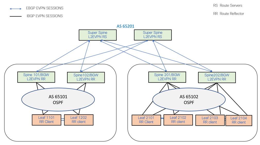
Each site is using its own IGP protocol like OSPF or IS-IS for the reachability of VTEPs loopback address and BGP peering loopback address. In this case study OSPF is used as the local site IGP. BGP EVPN is configured between Spine switches/BGW and Leaf switches to exchange EVPN routes. Spine switches will be the Route Reflectors (RR). EVPN routes are exchanged between the spine switches of each site to other sites with next hop (NH) not being changed. The super spine routers or inter site network (ISN) can act as route servers to reflect the EVPN routes of each site to other sites.
VXLAN Multi-Site- Data Plane
While connecting to different VXLAN fabric sites, each site has one or more border gateways (BGW) to other sites via the ISN. BGWs of each site terminate VXLAN tunnels from their own site and reoriginate tunnels from themselves to another site. The VXLAN tunnels are depicted using orange lines in the topology below. The endpoint and routing information between the sites are exchanged between the border gateways of the sites using BGP EVPN control plane.
All the border gateways of each site share the same anycast tunnel address, so that the VXLAN frame from the other site can reach any of the border gateways.
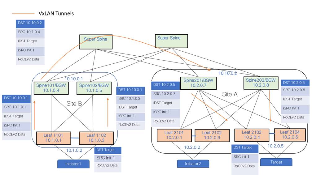
Initiators: Servers which initiate read or write operation with a Storage device
Targets: Storage devices.
The above topology explains the data path for the traffic originated from Initiator1 in Site B to Target in Site A.
● RoCEv2 traffic is received on a vpc pair Leaf1101 – Leaf1102 at site B.
● At VPC Pair Leaf1101-Leaf1102, the received traffic is encapsulated on the VXLAN header with source IP of the leaf switch’s VTEP address and the destination of the BGW anycast address of its own site.
● At local BGW-siteB, the VXLAN frame is re-originated with the SRC IP of the BGW IP and the destination, the anycast address of the remote site BGWs is Site A in this case.
● At site-A BGW, the VXLAN frame is re-originated with SRC IP of that BGW which receives the frame, and the destination VTEP IP of the VPC Pair where the target is located.
Achieving Lossless Behavior on VXLAN Fabric for RoCEv2 Traffic using PFC
To implement PFC for RoCEv2 traffic on a VXLAN fabric, first, let’s try to understand how we can classify the RoCEv2 traffic from other traffic. The best way to classify is by CoS values or by DSCP values rather than port numbers or IP addresses.
In this case study, RoCEv2 data traffic is classified by DSCP 24 and the control packets like CNP are classified with DSCP 48. The below NxOS CLI depicts the classification QoS config.
class-map type qos match-any CNP
match dscp 48
class-map type qos match-any ROCEv2
match dscp 24
During a read/write operation between an initiator and target, all the traffic is with DSCP value 24. When congestion occurs, PFC frames are generated at the congestion experiencing node towards the traffic source. After congestion is induced, the PFC frames are sent hop-by-hop towards the traffic source. Upon receiving a PFC pause frame, the traffic source reduces the rate at which the traffic is being sent. This process continues till the congestion is fully mitigated.
To implement PFC, priority flow control must be enabled on all the interfaces throughout the network fabric using the CLI “priority-flow-control mode on”.
RoCEv2 traffic must be put in the right queue, in this example, RoCEv2 is classified to queue 3 and RoCE control classified to priority queue which is queue 7.
policy-map type qos QOS_MARKING
class ROCEv2
set qos-group 3
class CNP
set qos-group 7
class class-default
set qos-group 0
interface Ethernet1/1
service-policy type qos input QOS_MARKING
priority-flow-control mode on
RoCEv2 classification is required on VTEP interface to classify the decapsulating traffic. VTEP nodes, by default in uniform mode, copies the QoS DSCP values from the inner IP header to the outer VXLAN header during encapsulation and the reverse process during decapsulation of the VXLAN header.
interface nve1
service-policy type qos input QOS_MARKING
To generate pause frame on a specific queue, the following network QoS configuration should be configured. In this case study, PFC pause frames are generated on queue 3. MTU must match the RoCEv2 traffic MTU for proper generation of pause frames when congestion occurs.
policy-map type network-qos qos_network
class type network-qos c-8q-nq3
pause pfc-cos 3
mtu 9216
class type network-qos c-8q-nq-default
mtu 9216
The network QoS config and the QoS queueing/scheduling configuration must be applied on the system level to apply for all the interfaces in the system.
system qos
service-policy type queuing output
QOS_EGRESS_PORT service-policy type network-qos qos_network
PFC walk through on VXLAN fabric
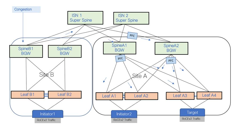
In the above VXLAN fabric topology there are two sites A & B. There are initiators on Site A and Site B and Target on Site A. Both the initiators are performing a read operation from the target.
PFC is configured on all the leaf nodes, spine/BGW nodes, and ISN so that the PFC hop-by-hop behavior is intact. QOS classification and queuing configuration are also done on all the nodes.
When Spine B1 towards leaf B1 experiences congestion, Spine B1 generates PFC towards ISN which in turn generates PFC towards Spine A1 or A2 hop by hop till it reaches the target to reduce the traffic rate. When there are multiple uplinks contributing to the congestion, PFC is generated towards the uplink which contributes towards the congestion rather than sending PFC on all the uplinks equally.
PFC generation can be verified using the following CLI:
show interface priority-flow-control
============================================================
Port Mode Oper (VL bmap) RxPPP TxPPP
============================================================
Ethernet1/1 On On (8) 9638881 12024
Ethernet1/2 On On (8) 0 0
Ethernet1/3 On On (8) 0 511
Ethernet1/4 On On (8) 35079 1205
Ethernet1/5 Auto Off 0 0
Ethernet1/6 Auto Off 0 0
--truncated---
show interface e1/1 priority-flow-control detail slot 1
=======
Ethernet1/1
Admin Mode: On
Oper Mode: On VL
bitmap: (8)
Total Rx PFC Frames: 9638881 Total
Tx PFC Frames: 12024
| |Priority0 |
|Priority1 |
|Priority2 |
|Priority3 |
|Priority4 |
|Priority5 |
|Priority6 |
|Priority7 |
|
| Rx |0 |
|0 |
|0 |
|9638881 |
|0 |
|0 |
|0 |
|0 |
| |
| Tx |0 |
|0 |
|0 |
|12024 |
|0 |
|0 |
|0 |
|0 |
| |
ECN on VXLAN Fabric
Explicit congestion notification bit on IP header is a 2-bit field which is set on the switch for the traffic experiencing congestion. In this case study, congestion was induced on SpineB1 BGW as shown in Figure-7. This ECN notification is always a forward notification. It is up to the receiving application to inform the sender about the congestion.
Two bits for ECN with the following options:
0x00 – Non ECN-Capable Transport (Non-ECT)
0x10 – ECN Capable Transport 0 (ECT-0)
0x01 – ECN Capable Transport 1 (ECT-1)
0x11 – Congestion Encountered (CE)
If ECN is enabled on the node, during network congestion, the switches change those two bits from 01 or 10 to 11.
For RoCEv2 traffic on VXLAN fabric, when congestion happens, the ECN bit is set on the outer VXLAN header. This ECN bit is copied to the inner header at the decapsulation VTEP. If the congestion occurs on the ingress leaf, the ECN bit is set on the inner header itself. In this case study, the receiving storage application informs the traffic source with CNP packets to reduce the rate. CNP is a special RoCEv2 packet with source UDP ports set to zero, destination set to 4791, and DSCP value set to 48 on the IP header. VXLAN fabric is configured with QOS classifying CNP packets to a high-priority queue. CNP packets are never dropped in the network because of the high-priority classification.
To enable ECN on VXLAN Fabric, the first step is to classify RoCEv2 traffic to the right queue. In our case study, RoCEv2 traffic is identified with DSCP 24 and classified to queue 3 and the CNP packets are classified to high priority queue.
policy-map type qos QOS_MARKING
class ROCEv2
set qos-group 3
class CNP
set qos-group 7
class class-default
set qos-group 0
interface Ethernet1/1
service-policy type qos input QOS_MARKING
In this case study, ECN is enabled on queue 3 with a minimum threshold of 150 Kbytes and a maximum threshold of 3000 Kbytes.
policy-map type queuing
QOS_EGRESS_PORT class type queuing c-out-8q-q6
bandwidth remaining percent 0
class type queuing c-out-8q-q5
bandwidth remaining percent 0
class type queuing c-out-8q-q4
bandwidth remaining percent 0
class type queuing c-out-8q-q3
bandwidth remaining percent 80
random-detect minimum-threshold 150 Kbytes maximum-threshold 3000 kbytes drop-probability 7 weight 0 ecn
class type queuing c-out-8q-q2
bandwidth remaining
percent 0 class type queuing
c-out-8q-q1
ECN Walk-through over VXLAN Fabric
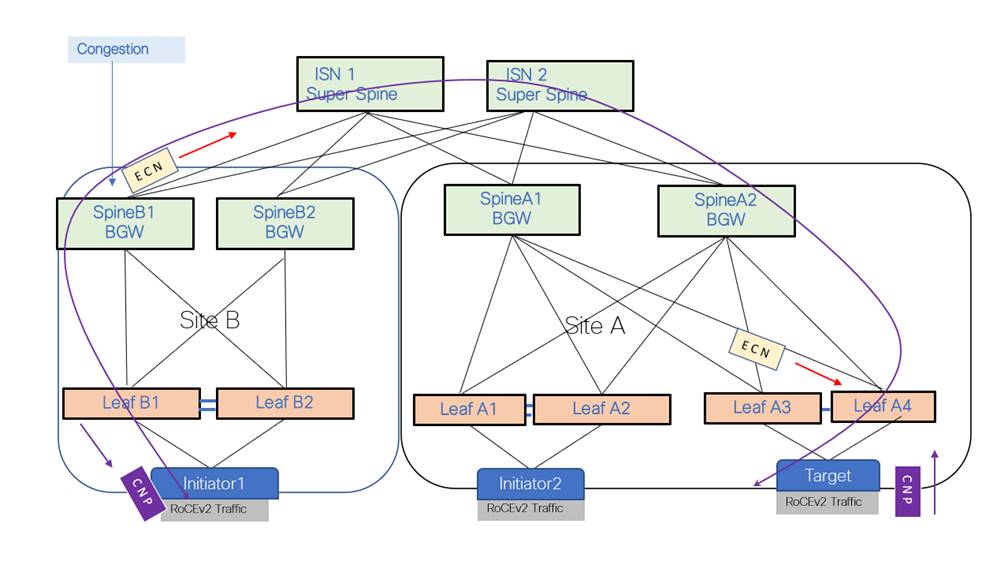
On the above VXLAN multi-site fabric, Initiator 1 on Site B and Initiator 2 on Site A are performing a read-and-write operation with the target at Site A. When congestion occurs at Site B, Spine B1/BGW, if the traffic exceeds the WRED threshold on queue 3, ECN bits are set on the outer header of the VXLAN packet at Spine B1/BGW. Spine A1 decapsulates the VXLAN packet and re-originates the packet towards Leaf A3. The ECN bits are copied to the inner header wherever decapsulation happens. After the target receives the RoCEv2 packet with ECN bit set, it will originate a CNP packet to Initiator 1 at Site B. Initiator 1, upon receiving the CNP reduces the read rate from the Target. Read/write operations between Initiator 2 and the target are never disturbed during this operation.
Queuing and Scheduling
The queuing and scheduling process allows you to control the bandwidth allocated to traffic classes so that you achieve the desired trade-off between throughput and latency.
You can apply weighted random early detection (WRED) to a class of traffic, which allows packets to be dropped based on the QoS group. The WRED algorithm allows you to perform proactive queue management to avoid traffic congestion.
You can shape traffic by imposing a maximum data rate on a class of traffic so that excess packets are retained in a queue. You can shape traffic by imposing a maximum data rate on a class of traffic so that excess packets are retained in a queue to shape and regulate the output rate. In addition, minimum bandwidth shaping can be configured to provide a minimum guaranteed bandwidth for a class of traffic. In addition, minimum bandwidth shaping can be configured to provide a minimum guaranteed bandwidth for a class of traffic.
You can limit the size of the queues for a particular class of traffic by applying either static or dynamic limits.
WRED ECN extension allows to mark packets instead of dropping when the average queue length exceeds a specific threshold value.
AFD is flow aware while WRED is not, the recommendation is to test AFD or WRED on their own environment and choose if it meets the dynamic nature of the storage traffic.
Approximate Fair Dropping (AFD) with Elephant Trap
AFD is an active queue-management scheme whose fundamental goal is to provide fair bandwidth allocation among flows that share a common egress queue. Fairness has two aspects. First, AFD distinguishes long-lived elephant flows from short-lived mice flows and exempts mice flows from the dropping algorithm so that mice flows get their fair share of bandwidth without being starved by bandwidth-hungry elephant flows. Second, AFD tracks elephant flows and subjects them to the AFD algorithm in the egress queue to grant them their fair share of bandwidth.
Elephant Trap (ETRAP)
AFD uses ETRAP to distinguish long-lived elephant flows from short-lived mice flows. A flow may be defined using multiple parameters, but typically the 5-tuple is used. ETRAP operates on the ingress side of a switch. It measures the byte counts of incoming flows and compares this against the ETRAP threshold that is defined in bytes. Flows with a byte count lower than the threshold are mice flows. After a flow crosses the threshold, it becomes an elephant flow and is moved to the elephant table for tracking. The ETRAP threshold is user configurable to allow customer traffic patterns to dictate what constitutes elephant flow.
The elephant table stores and tracks elephant flows. Elephant flows in the table are measured to determine their data arrival rate and their activity. The measured data rates are passed to the buffer management mechanism on egress queues, where the rates are used by the AFD algorithm to calculate the probability of drops for each flow. Elephant flows are aged out if they do not remain active for the configured timeout period. A user-configured, age-period timer, and a bandwidth threshold are used to evaluate the liveliness of an elephant flow. When its average bandwidth during the age-period time is lower than the configured bandwidth threshold, an elephant flow is inactive and will time-out and removed from the elephant flow table
show hardware flow etrap shows all the elephant flows that are likely to get the ECN bit set on that specific queue.
show hardware flow etrap
Elephant Flows
============================================================================================
Unit:Slc Index:Type Source Address Destination Address Ports(Src:Dst) Proto Approx_Rate
============================================================================================
0:0 0:2 10.108.1.4 17.1.1.4 1024:4791 17 264.320 Mb
0:0 1:2 10.108.1.8 17.1.1.8 1024:4791 17 264.000 Mb
0:0 2:2 17.1.1.9 10.108.1.9 1024:4791 17 518.560 Mb
0:0 4:2 10.106.1.3 18.1.1.3 1024:4791 17 295.840 Mb
Differences between WRED and AFD
Although WRED and AFD are both AQM algorithms, they have different approaches to manage congestion:
● WRED computes a random drop probability and drops the packets indiscriminately across all the flows in a class of traffic.
● AFD computes drop probability based on the arrival rate of incoming flows, compares it with the computed fair rate, and drops the packets from the elephant flows with no impact to the mice flows.
● AFD and WRED cannot be applied at the same time. Only one can be used in a system.
ECN can be generated either when traffic exceeds the WRED thresholds or when it exceeds the desired queue threshold of Approximate Fair dropping (AFD). AFD on PFC queue can be clubbed with dynamic packet prioritization (dpp) for mice flows in the default queue. The config example below has the same classification as discussed above but, on the network-qos, we have enabled ‘dpp’ to match the mice flows on the default queue. This config matches any mice flows like ‘ssh’ traffic and move those flows to high-priority queue.
On PFC enabled queue, ECN is generated when the AFD thresholds are exceeded.
policy-map type network-qos qos_network
class type network-qos c-8q-nq3
pause pfc-cos 3
mtu 9216
class type network-qos c-8q-nq-default
mtu 9216
dpp set-qos-group 7
policy-map type queuing 25G-QOS_EGRESS_PORT
class type queuing c-out-8q-q3
bandwidth remaining percent 80
afd queue-desired 375 kbytes ecn
class type queuing c-out-8q-q-default
bandwidth remaining percent 20
afd queue-desired 375 kbytes
class type queuing c-out-8q-q7
priority level 1
Initiator and Target Configurations
Cisco UCS servers running Linux with Mellanox Network adapters are the initiators and targets in the case study. The OFED driver is installed on the server. The OFED (OpenFabrics Enterprise Distribution) is open-source software for RDMA and kernel bypass.
Mellanox OFED (MLNX_OFED) is a Mellanox tested and packaged version of OFED that supports two interconnect types using the same RDMA (remote DMA) and kernel bypass APIs called OFED verbs – InfiniBand and Ethernet.
Mellanox Adapters' Linux Drivers for Ethernet and InfiniBand are available in all the major distributions, the matching Linux Kernel is needed when using inbox OFED driver.
Initiator Configuration
● Configure Driver and Library for NVME:
◦ Display the drive detail & modinfo detail -- show the nvme driver detail
$ ofed_info
$ modprobe rdma_cm
$ modprobe nvme-rdma
$ modprobe mlx5_ib
$ lsmod | grep nvme
◦ Display the ConnectX-5 Driver setting: -- ECN and CNP setting are correct
$ ibdev2netdev
$ mstconfig -d 5e:00.0 q | grep ECN --> 0
$ mstconfig -d 5e:00.1 q | grep CNP --> 48
$ mstconfig -d 5e:00.0 q | grep ECN --> 0
$ mstconfig -d 5e:00.1 q | grep CNP --> 48
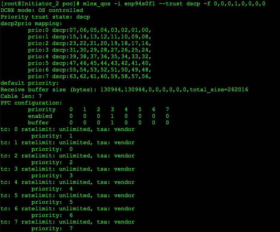
● Configure DSCP value for the NIC:
$ mlnx_qos -i enp94s0f1 --trust dscp; -f 0,0,0,1,0,0,0,0
 |
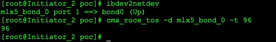
● Configure DSCP value for RoCE Traffic
$ cma_roce_tos -d mlx5_bond_0 -t 96
 |
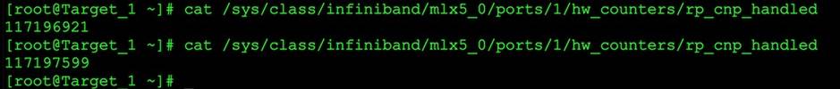
● Verify the interface CNP counter:
$ cat /sys/class/infiniband/mlx5_0/ports/1/hw_counters/np_cnp_sent
 |
● Verify the interface ECN counter:
$ /sys/class/infiniband/mlx5_0/ports/1/hw_counters/np_ecn_marked_roce_packets

Target Configuration 1: Use UCS Server as Target
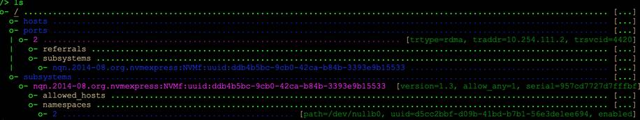
The UCS server can be converted into target. It is an easy way to run benchmark storage traffic test between servers. Use the nvmetcli utility to edit, view, and start an NVMe target on the UCS server. Use a null block device to assign to the nvmet subsystem. This block is used to communicate with the Initiators. Here is snapshot of NVMe Target on UCS server:
 |
Target Configuration 2: Pavilion Hyper Flash Array Configuration
Pavilion Architecture
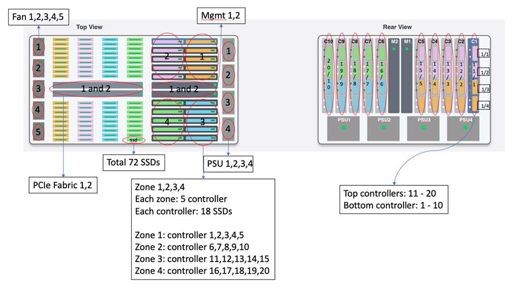
The pavilion storage platform being used in the lab is the industry’s first standard-based network storage device. It consists of 72 PCIe SSDs (Samsung SSD in this case), 20 controllers, 2 PCIe fabric (Gen-3), 2 management modules, 4 power supply unit and 5 Fans. The top and rear view of the device are shown below.
Configuration
Access the pavilion GUI by any kind of browser:

For the detailed configuration guide, see the pavilion’s Pavilion Array GUI Reference Guide. In this document, we list key components’ configurations with our real parameter values in the lab.
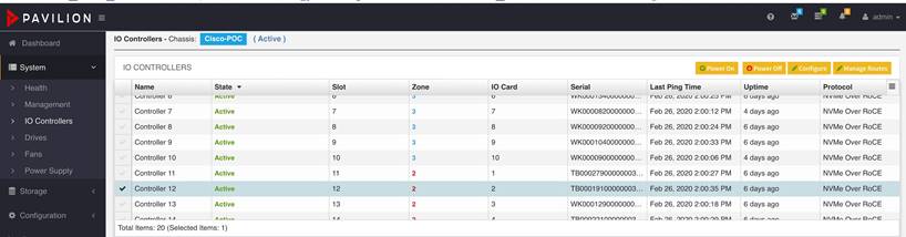
How to Configure a Controller?
To Configure a Protocol
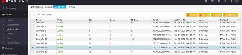
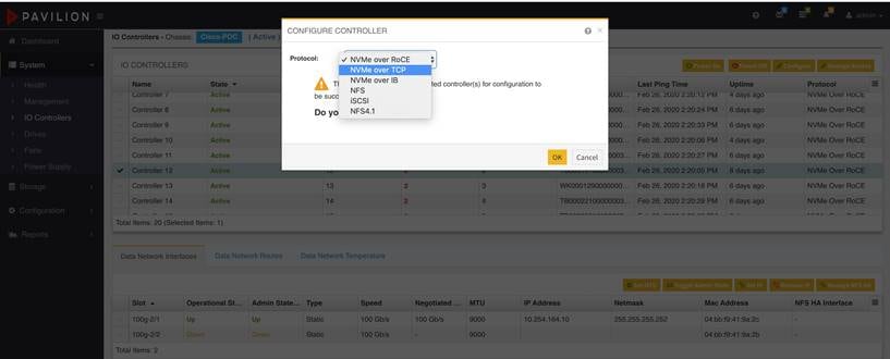
Go to system/IO Controllers, select any controller that you like to configure, click ‘Configure’ button on the right top corner:
 |
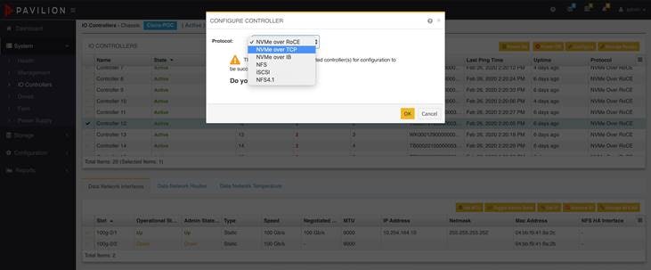
In the new dialog box, you can see protocols available, such as NVMe over RoCE (version2), NVMe over TCP, NVMe over IB, NFS, and iSCSI and so on. After the protocol is selected, click “OK” to complete the controller configuration:
 |
To Configure an IP Address
After completing the protocol on a controller, you can configure an IP address for a controller through the “Data Network Interface” tab on the bottom window; to click “Set IP” button at the top-right corner, then assign the IP and Netmask address on the dialog box; to click “OK” when it’s done.
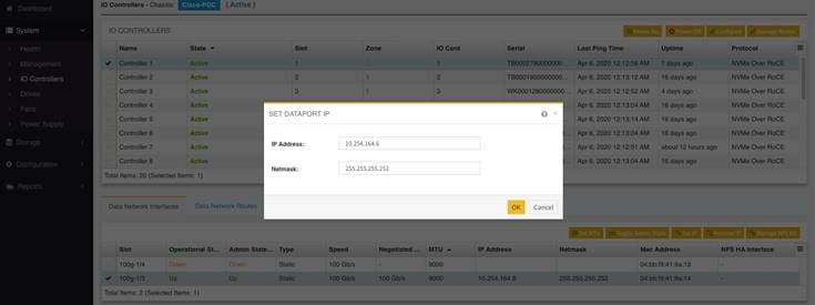 |
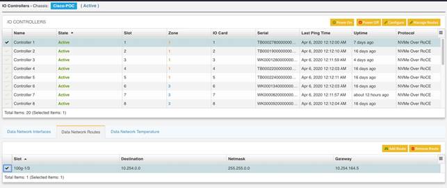
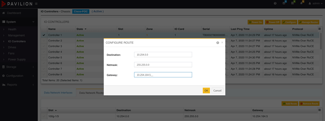
To Configure a Network Route
To move the next tab “Data Network Routes”, the network routes can be added to a specific controller. To click “Add Route” button at the top-right corner, you can add “destination route”, “netmask” and “gateway” on the dialog box, then click “OK” when it’s done.
 |
 |
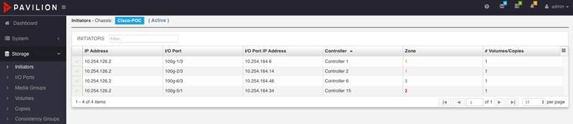
How to Check Initiators?
Frequently, we like to know which initiator is connecting the target (pavilion I/O port on the controller). There is no way to tell by the output of “nvme list” on the initiator.
Pavilion GUI provides a way to accomplish this. Go to “Storage/Initiator” and the output is showing the alive NVMe connections, including initiators’ IP, controller and its I/O number, zone number and so on.
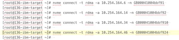 |
The above output is the commands for NVMe RoCE connect on the Linux initiator; if for NVMe tcp connect, “-t tcp -s 4420” parameters are needed.
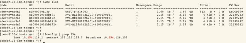 |
The above output is the result of NVMe RoCE connection on the Linux initiator; “10.254.126.2” is the initiator’s IP address.
 |
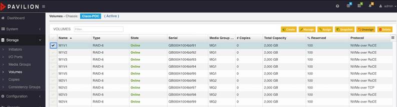
How to Modify the Protocol from NVMe over ROCE to NVMe over TCP for a volume?
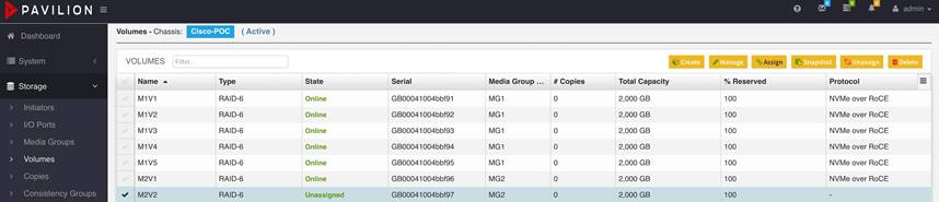
Step 1. To go to “Storage/Volumes”, select a volume and then click “unassign” in the top-right corner.
 |
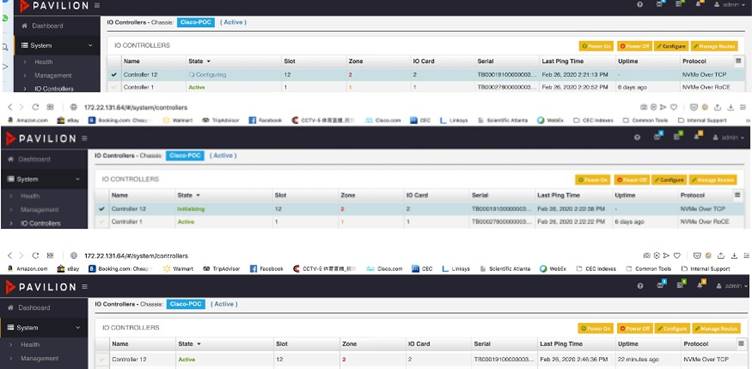
Step 2. To go to “System/IO Controller”, select the controller which is associated with the specific volume: then click “configure” button on the top-right corner and select a protocol that you like to configure on the dialog box:
Step 3. Click “configure” button on the top-right corner and select a protocol that you like to configure on the dialog box:
 |
Step 4. After completing the protocol selection, you can see different transitional state that is shown on the state column, “Configuring -> Initializing -> active”:
Step 5. To go back to “Storage/Volumes”, select the original volume with the present “unassigned” state, then click “assign” button on the top-right corner.
Step 6. After clicking “assign” button, to select the port which maps to the volume on the dialog box, click “OK” when it’s done.
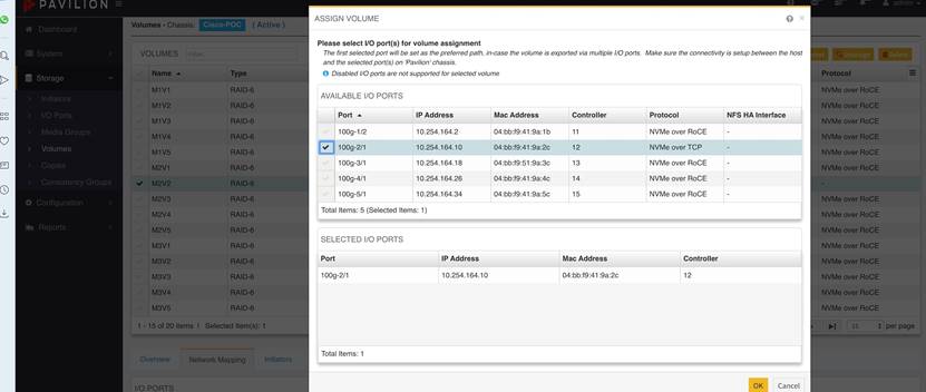 |
Step 7. After completing the volume assignment, you can see different transient states that are shown on the state column, “assigning -> active”
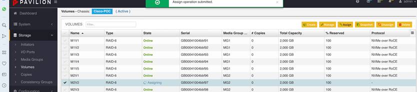 |
Establishing NVMe Connection:
Here is an example shows basic NVME operation on Linux: Discover, Connect, and Disconnect. The remote target: 10.254.108.2.
● NVME Discover: nvme discover -t rdma -a 10.254.108.2
The output contains the ‘subnqn’ value for the remote NVME target
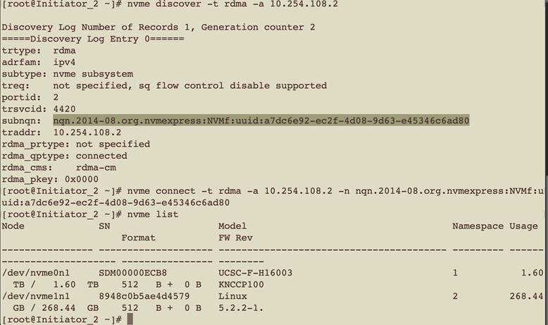
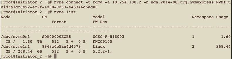
● NVME Connect nvme discover -t rdma -a 10.254.108.2 -n <subnqn.number>.
When Target is connected, it shows up under ‘nvme list’ output:
 |
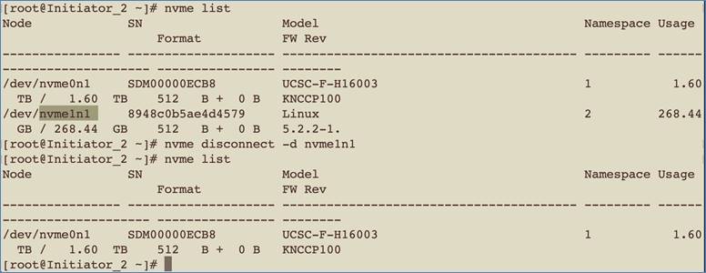
● NVME Disconnect nvme discover <nvme_drive_number>
FIO - Flexible I/O Storage Test tool:
FIO is an open-source, flexible I/O measuring tool that supports multiple threads, various queue depths, different measuring test duration, and many other parameters. FIO is an industry-standard tool for measuring storage performance in Linux. It can be run either by command line or configure file. In our lab, we used Configure file to run FIO tests.
FIO parameters:
The FIO configuration below is an example describing how to define and set a parameter. Certainly, the parameters in the file are the most popular ones but not all. For the entire parameter definition, see https://fio.readthedocs.io/en/latest/.
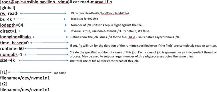 |
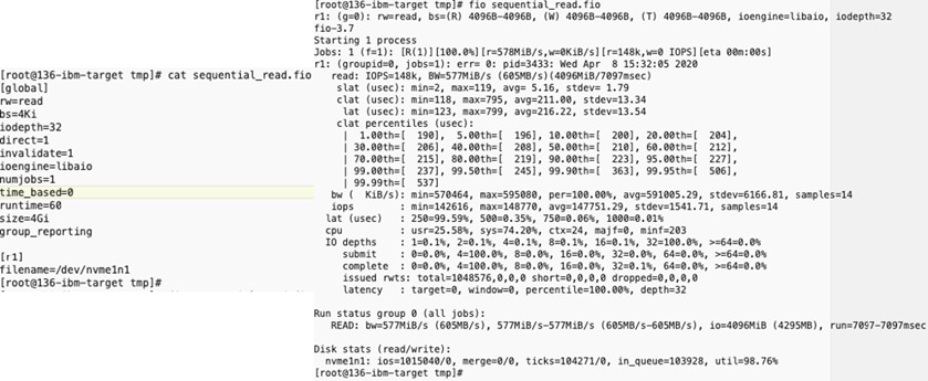
FIO output example – sequential read
On the left of the screenshot below, it defines that the FIO test is file size based (“size=4Gi”), instead of the duration based (“time_based=0”). The read/write pattern is sequential read (“rw=read”);
On the right of the screenshot below, it shows that the IOPS for job r1 is 148K per second; the average slat (submission latency) is 5.16 usec, the avg clat (completion latency) is 211 usec and the total avg latency is 216.22 usec; moreover, the CPU user and system usage are shown in the output; at the bottom of the output, the bw, io size, and running time are also shown. As for the clat percentile part, it means that the usec latency is associated with the x-th percentile.
slat – submission latency: this is the time that it took to submit I/O.
clat – completion latency: it is the time from submission to completion I/O.
lat – total latency: it’s the time from when the FIO created I/O to completion of the I/O operation.
 |
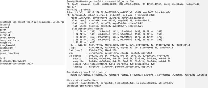
FIO output example - sequential write
 |
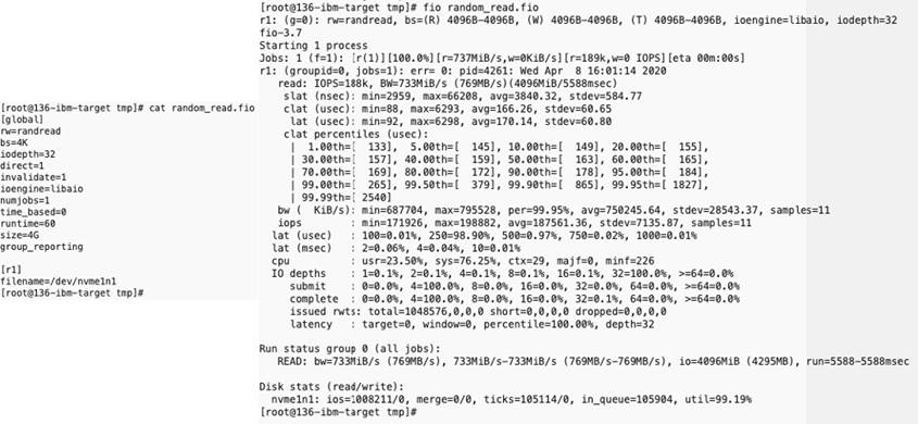
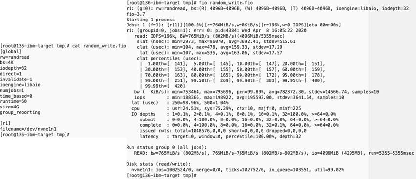
FIO output example - random read
 |
FIO output example - random write
FIO output example - random read/write
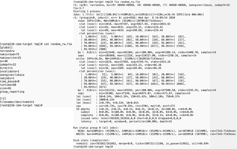 |
Running NVMe RoCE performance test with FIO:
For measuring the NVMe RoCE performance over Cisco N9K switches, we built up the spine-leaf topology as below: Spine switch is N9K-C9332C and Leaf switch is N9K-C9336C-FX2; the initiator is Cisco UCS server (C240-M5) and the target is Pavilion Data’s Rack Scale Storage platform (fully-loaded with 72 Samsung SSDs); all links are connected by 100G-based fiber cables. For more detailed specifications, see Cisco and Pavilion documentation, respectively.
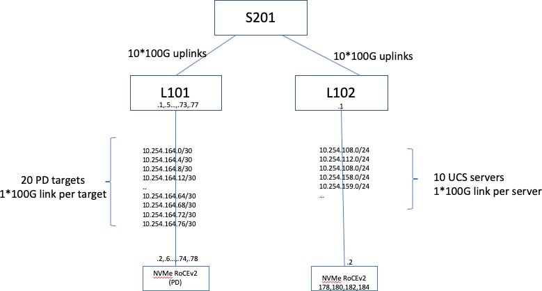 |
For maximizing the performance, each UCS initiator connects to 2 pavilion targets and meanwhile each target is located in a different zone so that there is no oversubscription on the 100G link between the server and the switch. For detailed connection mapping, see the following images.
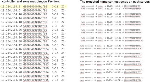 |
The NMVe RoCE test result is shown and monitored on the Pavilion GUI dashboard shown below. Meanwhile, the FIO configuration file is shown for reference.
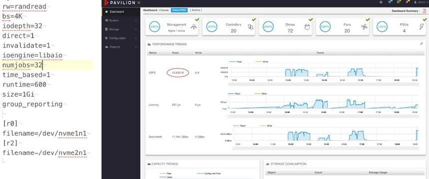 |
Reference
VXLAN Multi-Site Cisco White Paper
Intelligent Buffer Management on Cisco Nexus 9000 Series Switches White Paper
InfiniBand Architecture Specification
https://www.ciscolive.com/c/dam/r/ciscolive/us/docs/2019/pdf/BRKDCN-2213.pdf
NVME-oF Specification
https://nvmexpress.org/developers/nvme-of-specification/
nvme-CLI Command Reference
https://github.com/linux-nvme/nvme-cli
Flexible I/O Tester Reference
https://fio.readthedocs.io/en/latest/fio_doc.html
Pavilion GUI Configuration Guide
RDMA over Converged Ethernet (RoCE) on Cisco Nexus 9300
https://aboutnetworks.net/rocev2-on-nexus9k/
NVMe over Fabrics and RDMA for network engineers
https://aboutnetworks.net/nvme-and-nvmeof/
https://network.nvidia.com/pdf/solutions/benefits-of-RDMA-over-routed-fabrics.pdf
Legal Information
Cisco and the Cisco logo are trademarks or registered trademarks of Cisco and/or its affiliates in the U.S. and other countries. To view a list of Cisco trademarks, go to this URL: www.cisco.com/go/trademarks. Third-party trademarks mentioned are the property of their respective owners. The use of the word partner does not imply a partnership relationship between Cisco and any other company. (1110R)
Any Internet Protocol (IP) addresses and phone numbers used in this document are not intended to be actual addresses and phone numbers. Any examples, command display output, network topology diagrams, and other figures included in the document are shown for illustrative purposes only. Any use of actual IP addresses or phone numbers in illustrative content is unintentional and coincidental.
© 2023 Cisco Systems, Inc. All rights reserved.