VXLAN EVPN Multi-Site Design and Deployment White Paper
Available Languages
Bias-Free Language
The documentation set for this product strives to use bias-free language. For the purposes of this documentation set, bias-free is defined as language that does not imply discrimination based on age, disability, gender, racial identity, ethnic identity, sexual orientation, socioeconomic status, and intersectionality. Exceptions may be present in the documentation due to language that is hardcoded in the user interfaces of the product software, language used based on RFP documentation, or language that is used by a referenced third-party product. Learn more about how Cisco is using Inclusive Language.
This document describes how to achieve a Virtual Extensible LAN (VXLAN) Ethernet Virtual Private Network (EVPN) Multi-Site design by integrating VXLAN EVPN fabrics with EVPN Multi-Site architecture for seamless Layer 2 and Layer 3 extension. In addition to the technical details, this document presents design considerations and sample configurations to illustrate the EVPN Multi-Site approach. The VXLAN Border Gateway Protocol (BGP) EVPN fabric (or site) can be extended at Layer 2 and Layer 3 with various technologies. However, the sole focus of this document is on how this extension can be achieved by using EVPN Multi-Site architecture, an integrated interconnectivity approach for VXLAN BGP EVPN fabrics.
EVPN Multi-Site technology is based on IETF draft-sharma-multi-site-evpn.
VXLAN EVPN Multi-Site architecture is independent of the transport network between sites. Nevertheless, this document provides best practices and recommendations for a successful deployment.
This document assumes that the reader is familiar with the configuration of VXLAN BGP EVPN data center fabric (site-internal network). The VXLAN BGP EVPN fabric can be configured either manually or using Cisco® Data Center Network Manager (DCNM).
This document focuses entirely on design, deployment, and configuration considerations for the EVPN Multi-Site architecture and the related border gateways (BGWs). It assumes that the individual data center fabrics (site-internal networks) are already configured and up and running. The EVPN Multi-Site solution allows you to interconnect data center fabrics built on VXLAN EVPN technology. It also allows you to extend Layer 2 and Layer 3 connectivity to data center networks built with older (legacy) technologies (Spanning Tree Protocol, virtual Port Channel [vPC], Cisco FabricPath, etc.).
This section presents a brief overview of the technology underlying VXLAN EVPN Multi-Site architecture. It also presents several use cases.
For decades, organizations built hierarchical networks, either by building and interconnecting multiple network domains or by simply using hierarchical addressing mechanisms such as Internet Protocol (IP). With the presence of Layer 2 and the nonhierarchical address space, the large bridged domains have always presented a challenge for scaling and failure isolation. Now, with the rise of endpoint mobility, technologies to build more efficient Layer 2 extensions and bring back hierarchies are needed. Using dedicated interconnectivity that can bring back the lost hierarchy, Data Center Interconnect (DCI) technologies have been popular. However, although DCI can be used to interconnect multiple data centers, within the data center large fabrics have become common to facilitate borderless endpoint placement and endpoint mobility. As a result of this trend, network state explosion for MAC and ARP entries presented itself. VXLAN was supposed to address this challenge, but it has increased the challenge, with even larger Layer 2 domains being built as the location boundary was overcome by the capability of VXLAN to provide Layer 2 over Layer 3 networking.
For fabrics, the spine and leaf, fat tree, and folded Clos topologies became essentially the standard topologies. The new network topology models build well-designed hierarchical networks, but with the addition of VXLAN as an over-the-top network this hierarchy was being flattened out. While the network design in the underlying topology was predominantly Layer 3 and an efficient hierarchy was present, with the introduction of the overlay network this hierarchy became hidden. This flattening has both benefits and drawbacks. The approach of building a network over the top without touching every switch offers simplicity, and such a network can be extended across multiple locations. However, this approach presents risk in the absence of failure isolation, particularly when large and stretched Layer 2 networks are built with this new overlay networking design. Whatever is sent through the ingress point into the overlay network will leave at the respective egress point. These overlay networks use the “closest to the source” and “closest to the destination” approach and dynamically build tunnels from point to point wherever needed.
EVPN Multi-Site architecture brings back hierarchies to overlay networks. EVPN Multi-Site architecture introduces external BGP (eBGP) for VXLAN BGP EVPN networks, whereas until now interior BGP (iBGP) was predominant. Following the introduction of eBGP next-hop behavior, Autonomous Systems (ASs) at the Border Gateways (BGWs) were introduced, returning network control points to the overlay network. With this approach, hierarchies are efficiently used to compartmentalize and interconnect multiple overlay networks. Organizations also have a control point to steer and enforce network extension within and beyond a single data center.
VXLAN EVPN Multi-Site architecture is a design for VXLAN BGP EVPN–based overlay networks. It allows interconnection of multiple distinct VXLAN BGP EVPN fabrics or overlay domains, and it allows new approaches to fabric scaling, compartmentalization, and DCI.
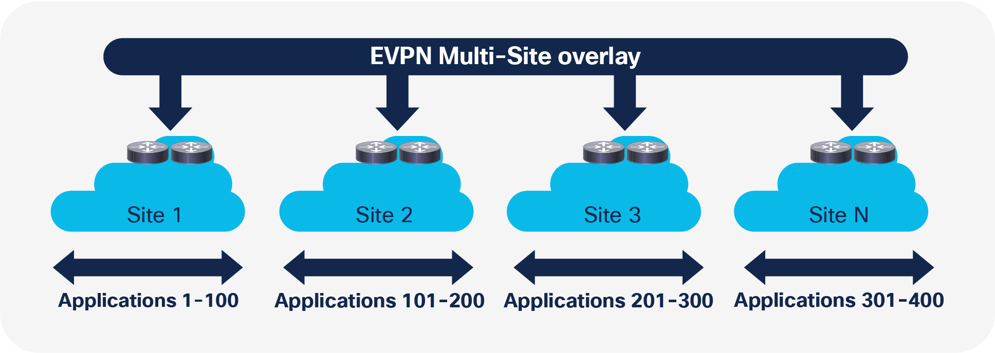
When you build one large data center fabric per location, various challenges related to operation and failure containment exist. By building smaller compartments of fabrics, you improve the individual failure and operation domains. Nevertheless, the complexity of interconnecting these various compartments precludes the pervasive rollout of such concepts, specifically when Layer 2 and Layer 3 extension is required (Figure 1).
Compartmentalization Example
VXLAN EVPN Multi-Site architecture provides integrated interconnectivity that doesn’t require additional technology for Layer 2 and Layer 3 extension. It thus offers the possibility of seamless extension between compartments and fabrics. It also allows you to control what can be extended. In addition to defining which VLAN or Virtual Routing and Forwarding (VRF) instance is extended, within the Layer 2 extensions you can also control broadcast, unknown unicast, and multicast (BUM) traffic to limit the ripple effect of a failure in one data center fabric.
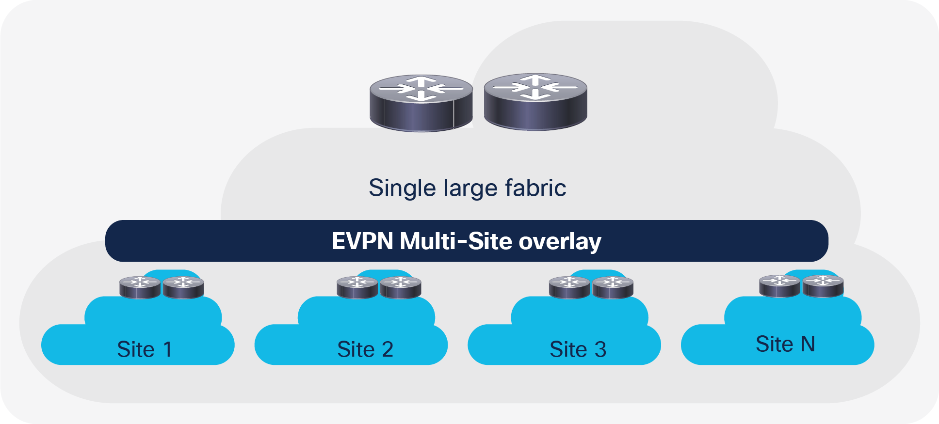
When you build networks using the scale-up model, one device or component typically reaches the scale limit before the overall network does. The scale-out approach offers an improvement for data center fabrics. Nevertheless, a single data center fabric also has scale limits, and thus the scale-out approach for a single large data center fabric exists.
In addition to the option to scale out within a single fabric, with EVPN Multi-Site architecture you can scale out in the next level of the hierarchy. Similarly, as you add more leaf nodes for capacity within a data center fabric, in EVPN Multi-Site architecture you can add fabrics (sites) to horizontally scale the overall environment. With this scale-out approach in EVPN Multi-Site architecture, in addition to increasing the scale, you can contain the full-mesh adjacencies of VXLAN between the VXLAN Tunnel Endpoints (VTEPs) in a fabric (Figure 2).
Scale Example
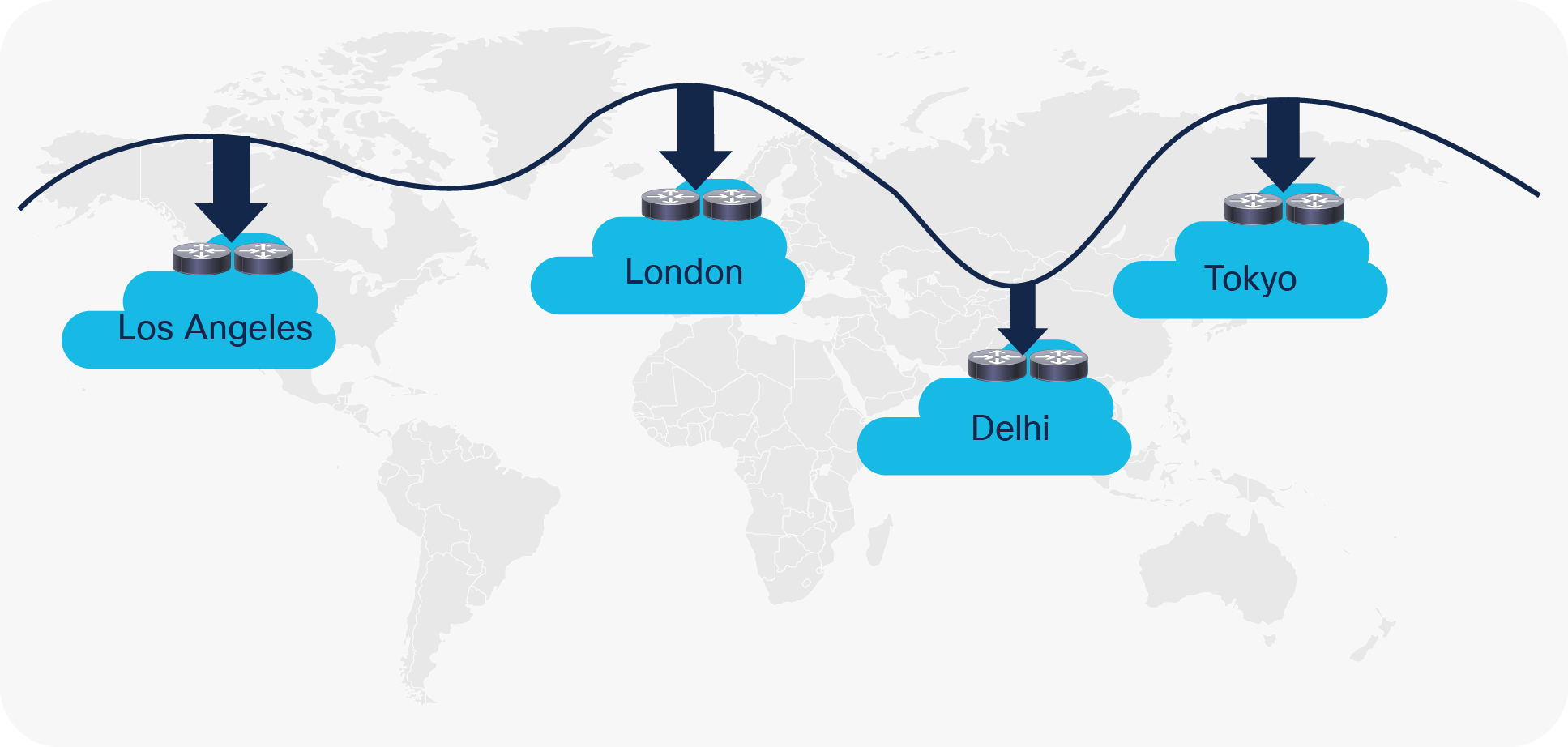
EVPN Multi-Site architecture can also be used for DCI scenarios (Figure 3). As with the compartmentalization and scale-out within a data center, EVPN Multi-Site architecture was built with DCI in mind. The overall architecture allows single or multiple sites per data center to be positioned and interconnected with single or multiple sites in a remote data center. With seamless and controlled Layer 2 and Layer 3 extension through the use of VXLAN BGP EVPN within and between sites, the capabilities of VXLAN BGP EVPN itself have been increased. The new functions related to network control, VTEP masking, and BUM traffic enforcement are only some of the features that help make EVPN Multi-Site architecture the most efficient DCI technology.
Data Center Interconnect Example
Table 1 summarizes the requirements for EVPN Multi-Site architecture. Table 1 provides the hardware and software requirements for the Cisco Nexus® 9000 Series Switches that provide the EVPN Multi-Site BGW function.
Table 1. Minimum software and hardware requirements EVPN Multi-Site border gateway
| Item |
Requirement |
| Cisco Nexus hardware |
● Cisco Nexus 9300 EX platform
● Cisco Nexus 9300 FX platform
● Cisco Nexus 9300 FX2 platform
● Cisco Nexus 9300 FX3 platform
● Cisco Nexus 9300-GX platform
*
● Cisco Nexus 9332C platform
● Cisco Nexus 9364C platform
● Cisco Nexus 9500 platform with X9700-EX line card
● Cisco Nexus 9500 platform with X9700-FX line card
● Cisco Nexus 9500 platform with X9700-GX line card
|
| Cisco NX-OS Software |
Cisco NX-OS Software Release 7.0(3)I7(1) or later |
Note: The hardware and software requirements for the site-internal BGP Route Reflector (RR) and VTEP of a VXLAN BGP EVPN site remain the same as those without the EVPN Multi-Site BGW. This document does not cover the hardware and software requirements for the VXLAN EVPN site-internal network. The “For more information” section at the end of this document includes links that provide access to the Cisco websites specific to VXLAN BGP EVPN deployments.
Other design considerations for site-internal and site-external hardware and software are discussed in the following sections.
This section presents technical information about the main components of the EVPN Multi-Site architecture and describes failure scenarios.
The main functional component of the EVPN Multi-Site architecture is the border gateway, or BGW. BGWs separate the fabric-side (site-internal fabric) from the network that interconnects the sites (site-external DCI) and mask the site-internal VTEPs.
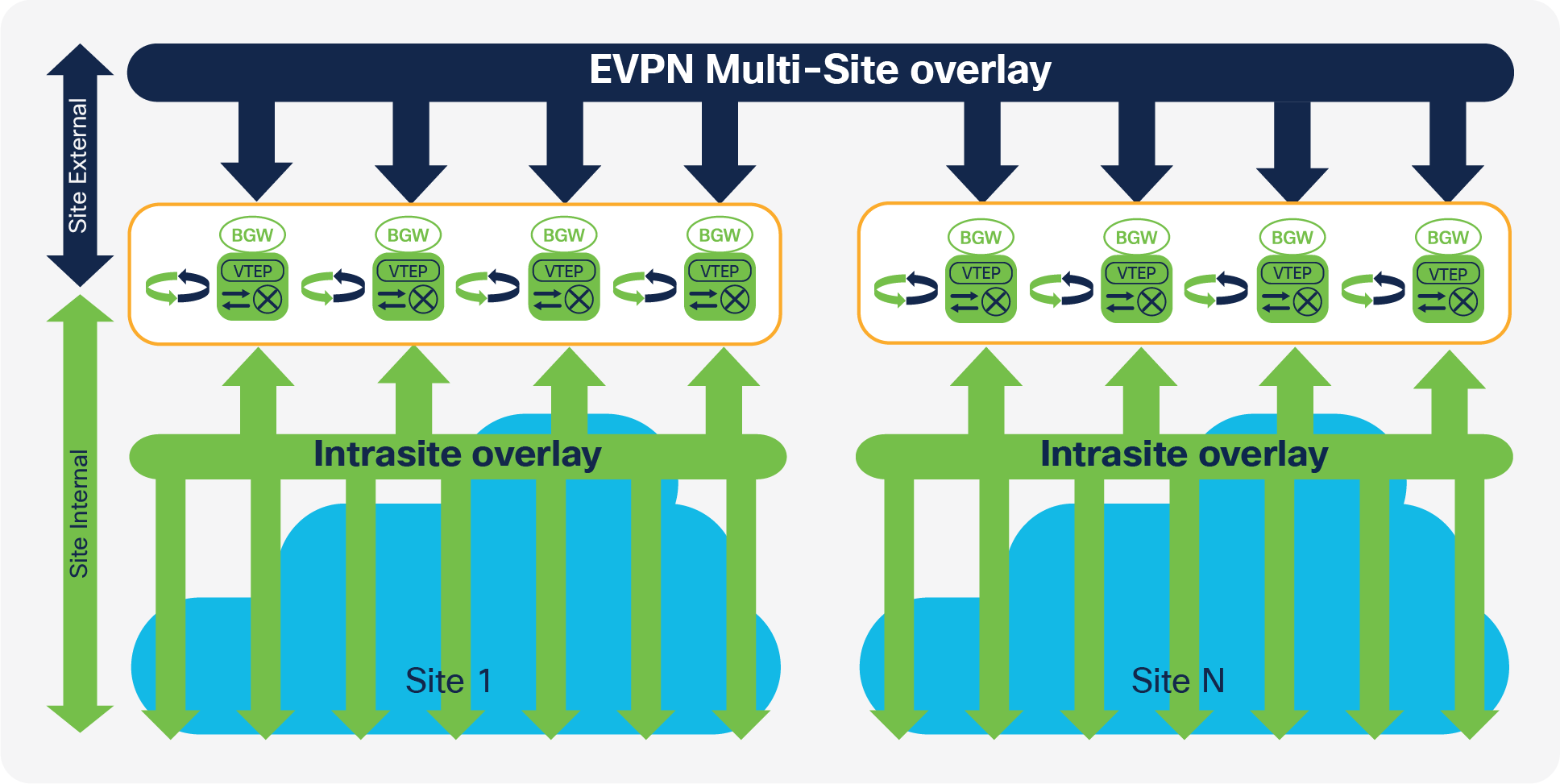
Commonly, an EVPN Multi-Site deployment consists of two or more sites, which are interconnected through a VXLAN BGP EVPN Layer 2 and Layer 3 overlay (Figure 4). In this scenario, the BGW is connected to the site-internal VTEPs (usually through spine nodes) and to a site-external transport network that allows traffic to reach the BGWs at other, remote sites. The BGWs at the remote sites have site-internal VTEPs behind them. Only the underlay IP addresses of the BGWs are seen inside the transport network between the BGWs. The site-internal VTEPs are always masked behind the BGWs.
EVPN Multi-Site Deployment
From a BGW perspective, the role of the site-internal VTEPs is to share the common VXLAN and BGP-EVPN functions. To interoperate with a BGW, a site-internal node must support the following functions:
● VXLAN with Protocol-Independent Multicast (PIM) Any-Source Multicast (ASM) or ingress replication (BGP EVPN Route Type 3) in the underlay
● BGP EVPN Route Type 2 and Route Type 5 for the overlay control plane
● Route reflector capable of exchanging BGP EVPN Route Type 4
● VXLAN Operations, Administration, and Maintenance (OAM)–capable devices for end-to-end OAM support
From the point of view of the site-external network, no specific requirements are demanded apart from IP transport reachability between the BGWs and accommodation of an increased Maximum Transmission Unit (MTU) packet size. The BGWs always use Ingress Replication (IR) for Layer 2 BUM traffic between BGWs in different sites, but they can use PIM ASM or ingress replication within a given site. This capability provides flexibility for existing deployments and transport independence for the site-external network.
Note: EVPN Multi-Site architecture uses VXLAN encapsulation for the data plane, which requires 50 or 54 bytes of overhead on top of the standard Ethernet MTU (1550 or 1554).
The BGW performs the internal-to-external site-separation procedure locally. Therefore, the BGW doesn’t require a neighboring device to perform this function. Just as a traditional VTEP can connect from a site-internal network to a BGW, a traditional VTEP can also connect to a BGW from a site-external network. That is, a BGW at the source site doesn’t require a neighboring BGW at the destination site; a traditional VTEP will suffice. This flexibility built into the BGW allows deployments beyond the traditional EVPN Multi-Site pairings. One such deployment case is described in the “Shared border” section of this document, and one is described in the “Legacy site integration” section.
Note that even though a traditional VTEP would work to connect to a BGW from a site-external network, such externally connected VTEPs would not perform any extended BGW functions such as site-internal VTEP masking.
With EVPN Multi-Site architecture, two placement locations can be considered for the BGW. A dedicated set of BGWs can be placed at the leaf layer, with the BGWs connected to the spine just like any other VTEP in the fabric (site-internal VTEPs). Alternatively, BGWs can be co-located on the spine of the fabric. If the BGW is on the spine, many functions are overloaded together: for instance, route-reflector, Rendezvous-Point (RP), east-west traffic, and external connectivity functions. In this case, you need to consider additional factors related to scale, configuration, and failure scenarios.
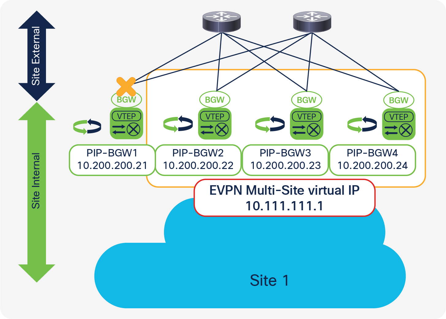
The anycast BGW (A-BGW) performs the BGW function as described in the previous section. The A-BGW allows the scaling of the BGWs horizontally in a scale-out model and without the fate sharing of interdevice dependencies. As of Cisco NX-OS 7.0(3)I7(1), the A-BGW is available on the Cisco Nexus 9000 Series cloud-scale platforms (Cisco Nexus 9000 Series EX and FX platforms), with up to four anycast BGWs available per site (Figure 5).
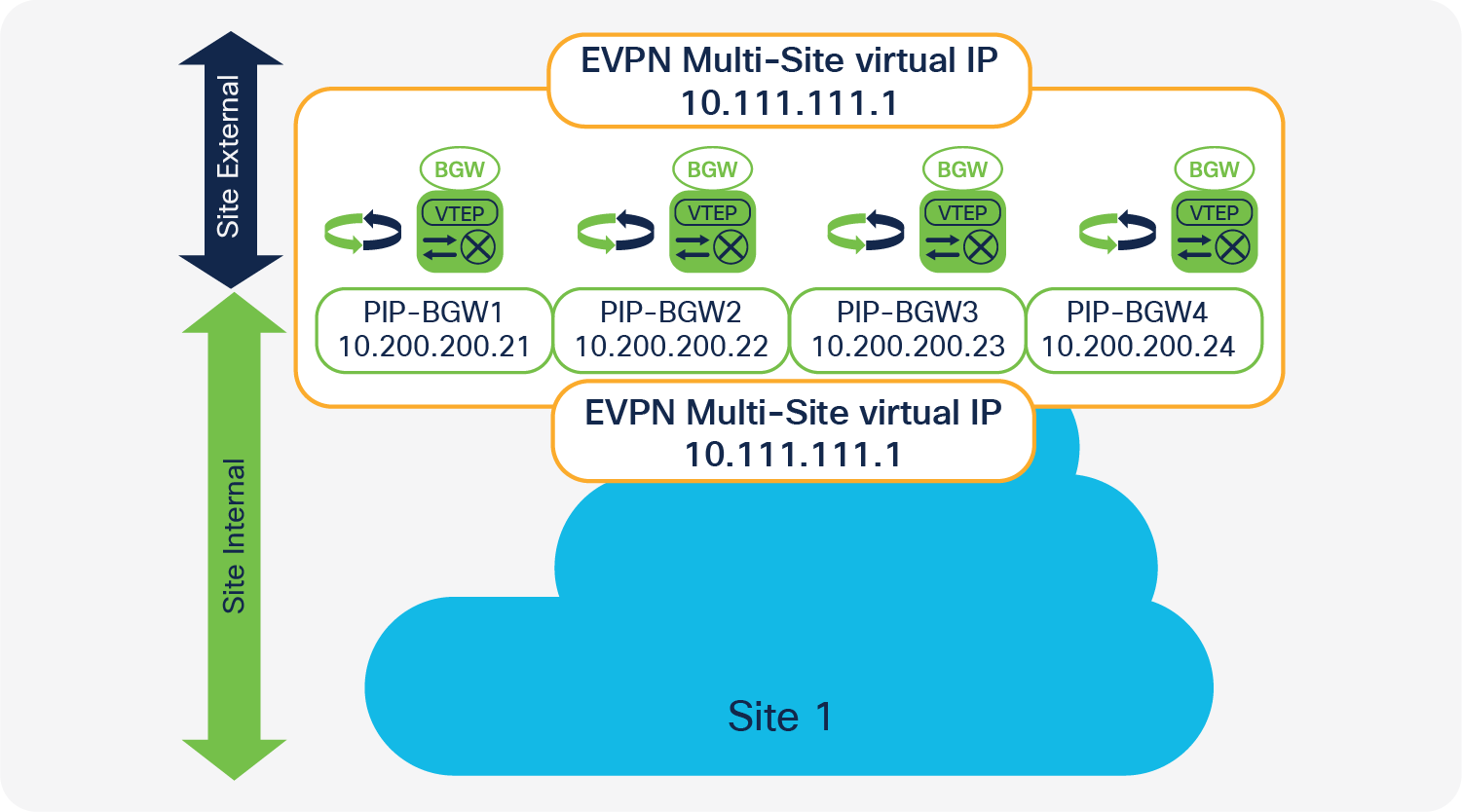
Anycast Border Gateway
The name “A-BGW” refers to the sharing of a common Virtual IP (VIP) address or anycast IP address between the BGWs in a common site. This document uses the virtual IP address to refer also to the EVPN Multi-Site anycast IP address.
The virtual IP address on the BGW is used for all data-plane communication leaving the site and between sites when the EVPN Multi-Site extension is used to reach a remote site. The single virtual IP address is used both within the site to reach an exit point and between the sites, with the BGWs always using the virtual IP address to communicate with each other. The virtual IP address is represented by a dedicated loopback interface associated with the Network Virtualization Endpoint (NVE) interface (multisite border-gateway interface loopback100).
With this approach, and with the existence of an Equal-Cost Multipath (ECMP) network, all BGWs are always equally reachable and active for data-traffic forwarding. The underlay transport network within or between the sites is responsible for hashing the VXLAN traffic among the available equal-cost paths. This approach avoids polarization, given the entropy of VXLAN, and it increases resiliency. If one or more BGWs fail, the remaining BGWs still advertise the virtual IP address and hence are immediately available to take over all the data traffic. The use of anycast IP addresses or virtual IP addresses provides network-based resiliency, instead of resiliency that relies on device hellos or similar state protocols.
In addition to the virtual IP address or anycast IP address, every BGW has its own individual personality represented by the primary VTEP IP (PIP) address (source-interface loopback1). The PIP address is responsible in the BGW for handling BUM traffic. Every BGW uses its PIP address to perform BUM replication, either in the multicast underlay or when advertising BGP EVPN Route Type 3 (inclusive multicast), used for ingress replication. Therefore, every BGW has an active role in BUM forwarding. Like the virtual IP address, the PIP address is advertised to the site-internal network as well as to the site-external network. The PIP address is used to handle BUM traffic between BGWs at different sites, because EVPN Multi-Site architecture always uses ingress replication for this process.
The PIP address is also used in two additional scenarios that are closely related.
If the BGW is providing external connectivity with VRF-lite next to the EVPN Multi-Site deployment, routing prefixes that are learned from the external Layer 3 devices are advertised inside the VXLAN fabric with the PIP address as the next-hop address. From the BGW’s point of view, these externally learned IP prefixes are considered to originate locally from a BGW, using the BGP EVPN address family. This process creates an individual BGP EVPN Route Type 5 (IP prefix route) from every BGW that learned a relevant IP prefix externally. In the best case, your site-internal network has an ECMP route to reach non-EVPN Multi-Site networks.
Note: External learned IP prefixes can be redistributed to BGP EVPN from any BGP IPv4/IPv6 unicast, Open Shortest Path First (OSPF), or other static or dynamic routing protocol that allows redistribution to BGP EVPN.
A closely related scenario is the case in which the BGW advertises an IP prefix with its own PIP address through local connectivity. An endpoint can be directly connected to a BGW, but its IP address can be learned only through routing on a physical interface or subinterface. The all-active connection of Layer 4 through Layer 7 (L4-L7) network services (for example, firewalls and load balancers) can be achieved through ECMP routing with a static or dynamic routing protocol.
Note: The use of VLANs and Switch Virtual Interfaces (SVIs) local to one BGW or across multiple BGWs is not currently supported. This restriction also applies to Layer 2 port channels with or without multihoming. For L4-L7 network services that require this connectivity model, use a site-internal VTEP (a traditional VTEP).
Every A-BGW actively participates in the forwarding of BUM traffic. Specifically, the Designated-Forwarder (DF) function for BUM traffic is distributed on a per–Layer 2 VXLAN Network Identifier (VNI) basis. To synchronize the designated forwarders, BGP EVPN Route Type 4 (Ethernet segment route) updates are exchanged between the BGWs within the same site (Figure 6).
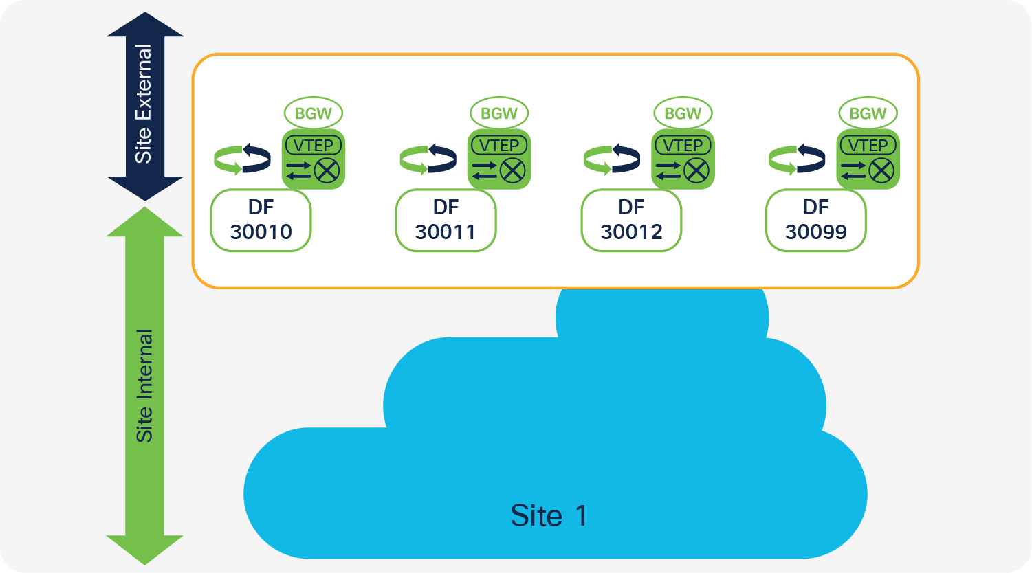
Designated Forwarder
To participate in the designated-forwarder election, the configuration of the same site ID is required. This ID is defined as part of the BGW configuration (evpn multisite border-gateway <site-id>). In addition to the site ID, the use the same Layer 2 VNI is needed to elect the designated forwarder from among the eligible BGWs.
The designated-forwarder assignment is performed on a per–Layer 2 VNI basis, using a round-robin process to distribute assignments equally. An ordinal list of PIP addresses is used, and based on all the Layer 2 VNI order of configuration or ordinal list, the designated-forwarder role is distributed in a round-robin fashion.
Note: Every BGW will have an active designated-forwarder role if the number of Layer 2 VNIs exceeds the number of BGWs.
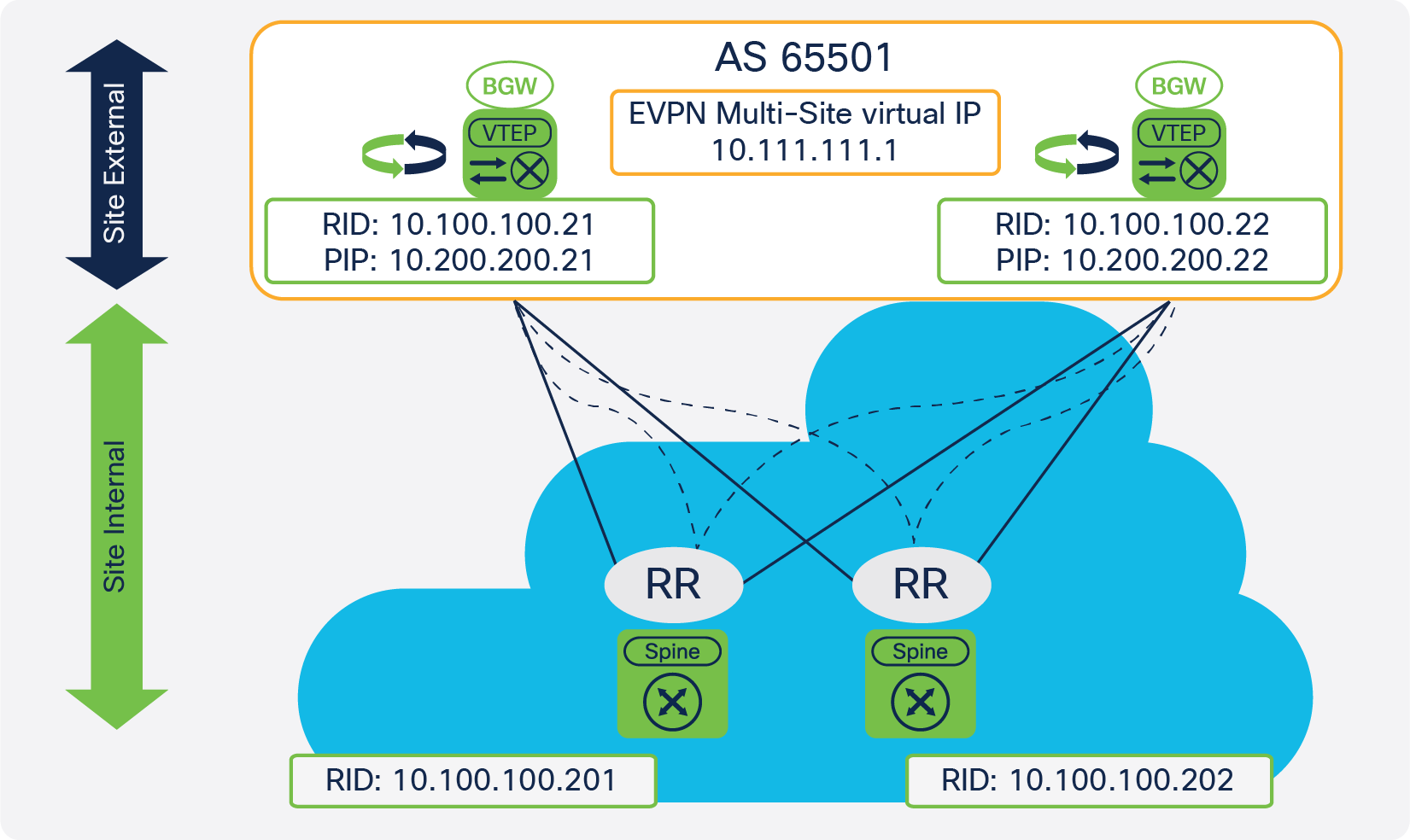
To exchange the designated-forwarder election messages between the BGWs, BGP EVPN peering is required because the election messages consist of BGP EVPN Route Type 4 advertisements. Most naturally, the BGW would peer with a site-internal (fabric) route reflector, which also has all the endpoint information from within the site-internal VTEPs. With the route reflector already present in the fabric, and with all VTEPs, including the BGW, peering with it, the exchange of designated-forwarder election messages is achieved (Figure 7).
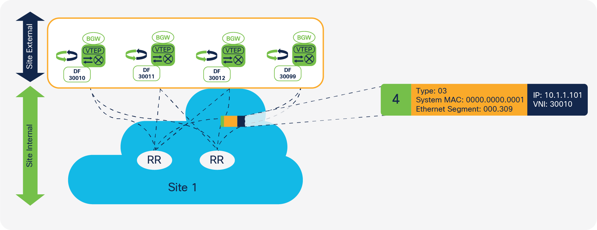
Designated Forwarder election using Route Reflectors
In cases in which no route reflector exists, or in which the route reflector is not capable of relaying BGP EVPN Route Type 4, a iBGP session can be considered as an alternative. The iBGP peering must be EVPN address family enabled and have a full mesh established between the loopback interfaces of the BGWs.
Note: The BGP EVPN Route Type 4 exchange should occur only through site-internal peerings. If the designated-forwarder election exchange occurs through the site-internal (fabric) and site-external (DCI) networks, extended convergence time may be experience in certain failure scenarios. By default, this peering is enforced through the BGP autonomous system path-loop prevention mechanism, because the source and destination autonomous systems for the site-local BGWs are the same. In cases in which functions such as as-override and allowas-in are used, you must pay special attention to the site-external overlay peering.
The BGW is the binding device between the site-internal VTEPs and everything that is site external. Because of the importance of the BGW, you need to consider not only scale and resiliency, but also the behavior during a failure situation. For EVPN Multi-Site architecture, you need to consider two main failure scenarios: a failure in the fabric (site-internal failure) and a failure in the site-external area. With the recommended resiliency for the overall connectivity design, EVPN Multi-Site architecture is equipped to resist failures that previously required significant convergence time or recalculation of the data path.
Fabric Isolation
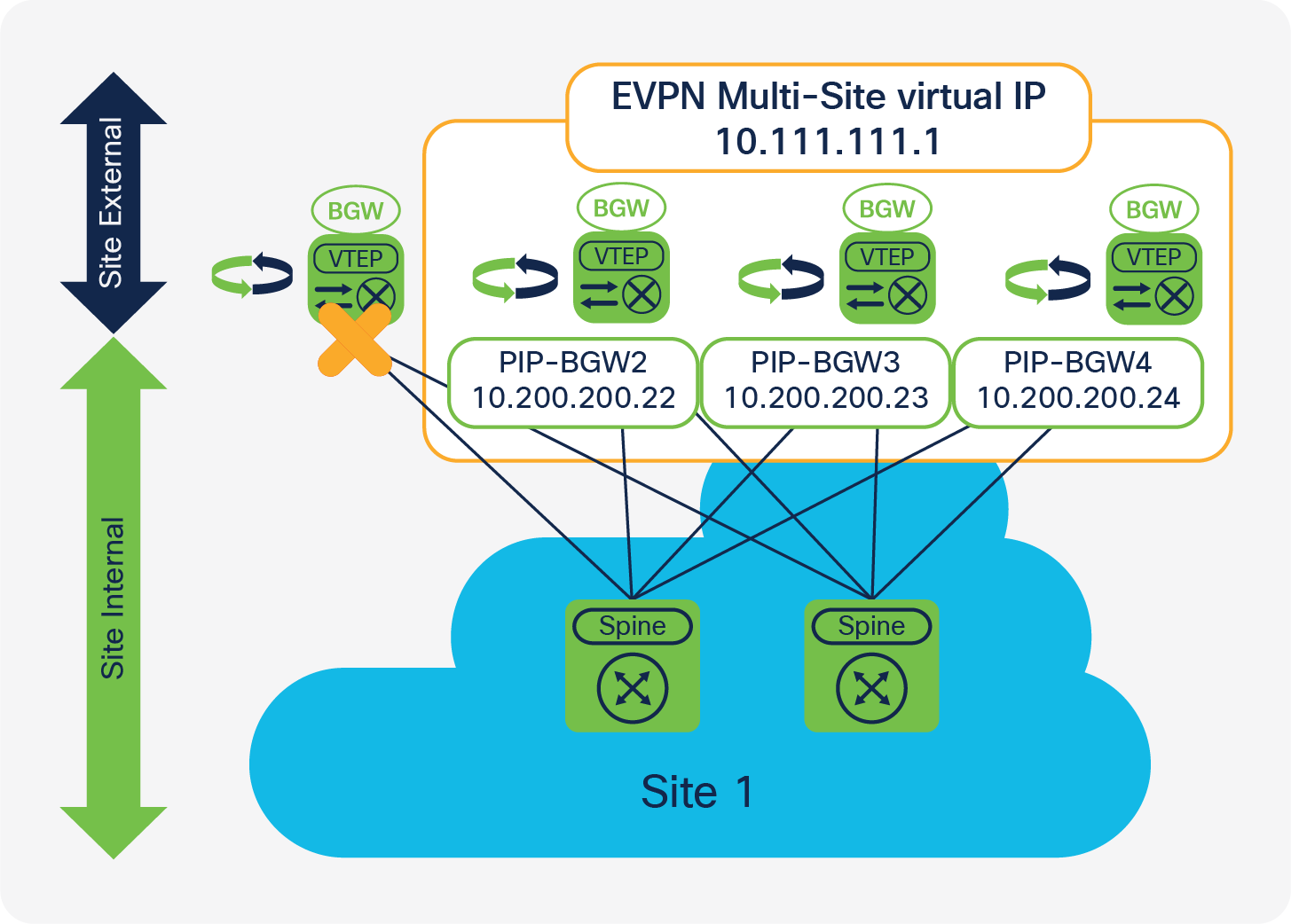
Failure detection in the site-internal interfaces is one of the main mechanisms offered by EVPN Multi-Site architecture to reduce traffic outages. The site-internal or fabric interfaces commonly are connected to the spine layer, to which more VTEPs are connected. Assuming a fabric with two spine switches and four BGWs, a full mesh of links is established between the neighboring spine and BGW interfaces. On the BGW itself, the site-internal interfaces are specially configured to understand their locations in the network (evpn multisite fabric-tracking).
The EVPN Multi-Site fabric-tracking function detects whether one or all of the site-internal interfaces are available. As long as one of these interfaces is operational and available, the BGW can extend Layer 2 and Layer 3 traffic to remote sites. If all fabric-tracking interfaces are reported to be down, the following steps are performed:
● The isolated BGW stops advertising the virtual IP address to the site-external underlay network.
● The isolated BGW withdraws all of its advertised BGP EVPN routes (Route Type 2, Route Type 3, Route Type 4, and Route Type 5).
● The remaining BGWs withdraw all BGP EVPN Route Type 4 (Ethernet segment) routes received from the now isolated BGW because reachability is missing.
Note: You do not need to stop advertising from the site-internal underlay because all site-internal interfaces are considered to be down.
As a result of these actions, the BGW will be isolated from a VTEP perspective in both the site-internal and site-external networks (Figure 8). Therefore, all traffic originating from remote sites and destined for the virtual IP address is rerouted to the remaining BGWs that still host the virtual IP address and have it active. With the disappearance of the BGW traffic to the site-internal network, the advertisements of this PIP address and the capability to participate in designated-forwarder election is removed. As a consequence, the designated-forwarder role for the VNIs previously “owned” by the isolated BGW is now renegotiated between the remaining BGWs.
On recovery from a failure of all site-internal interfaces, first the underlay routing adjacencies are established and then the site-internal BGP sessions to the route reflector are reestablished. To allow the underlay and overlay control planes to converge before data traffic is forwarded by the BGW, you can configure a restore delay for the virtual IP address to delay its advertisement to the underlay network control plane. The EVPN Multi-Site delay-restore setting is a subconfiguration of the BGW site ID configuration (delay-restore time 300).
DCI Isolation
Similar to the site-internal interfaces, the site-external interfaces in EVPN Multi-Site architecture use interface failure detection. The site-external or DCI interfaces commonly are connected to the network between sites, at which more BGWs are present. The site-external interfaces offer a configuration similar to that for the site-internal interfaces to understand their locations and the need for tracking (evpn multisite dci-tracking).
The DCI-tracking function in EVPN Multi-Site architecture detects whether one or all of the site-external interfaces are up and operational. If one of the many interfaces remains up, the site-external interfaces are considered working, and the BGW can extend Layer 2 and Layer 3 services to remote sites.
In the rare case in which all DCI-tracking interfaces are down, the BGW performs the following actions:
● It stops advertising the virtual IP address to the site-internal underlay network.
● It withdraws all BGP EVPN Route Type 4 (Ethernet segment) route advertisement.
● It converts the BGW to a traditional VTEP (the PIP address stays up).
Note: You do not need to stop advertising from the site-external underlay because all site-external interfaces are considered to be down.
As a result of these actions, the BGW will continue to operate only as a site-internal VTEP. Therefore, all traffic to the virtual IP address is rerouted to the remaining BGWs that still host the virtual IP address and have it active. The advertisements to participate in designated-forwarder election are removed from the DCI-isolated BGW (Figure 9).
On recovery from a failure of all site-external interfaces, first the underlay routing adjacencies are established, and then the site-external BGP sessions are reestablished. To allow the underlay and overlay control planes to converge before data traffic is forwarded by the BGW, you can configure a restore delay for the virtual IP address. The EVPN Multi-Site delay-restore setting is a subconfiguration of the BGW site ID configuration (delay-restore time 300) and applies to both the site-internal and site-external networks.
EVPN Multi-Site architecture has many different deployment scenarios that apply to different use cases. The topology that works best depends on the use case.
This document considers the following major topologies:
● DCI
◦ BGW to cloud
◦ BGW back to back
● Multistage Clos (three tiers)
◦ BGW between spine and superspine
◦ BGW on spine
Although all of these designs look similar, you need to consider different factors when deploying them. The following sections describe the four topologies and the deployment details.
BGW-to-Cloud Model
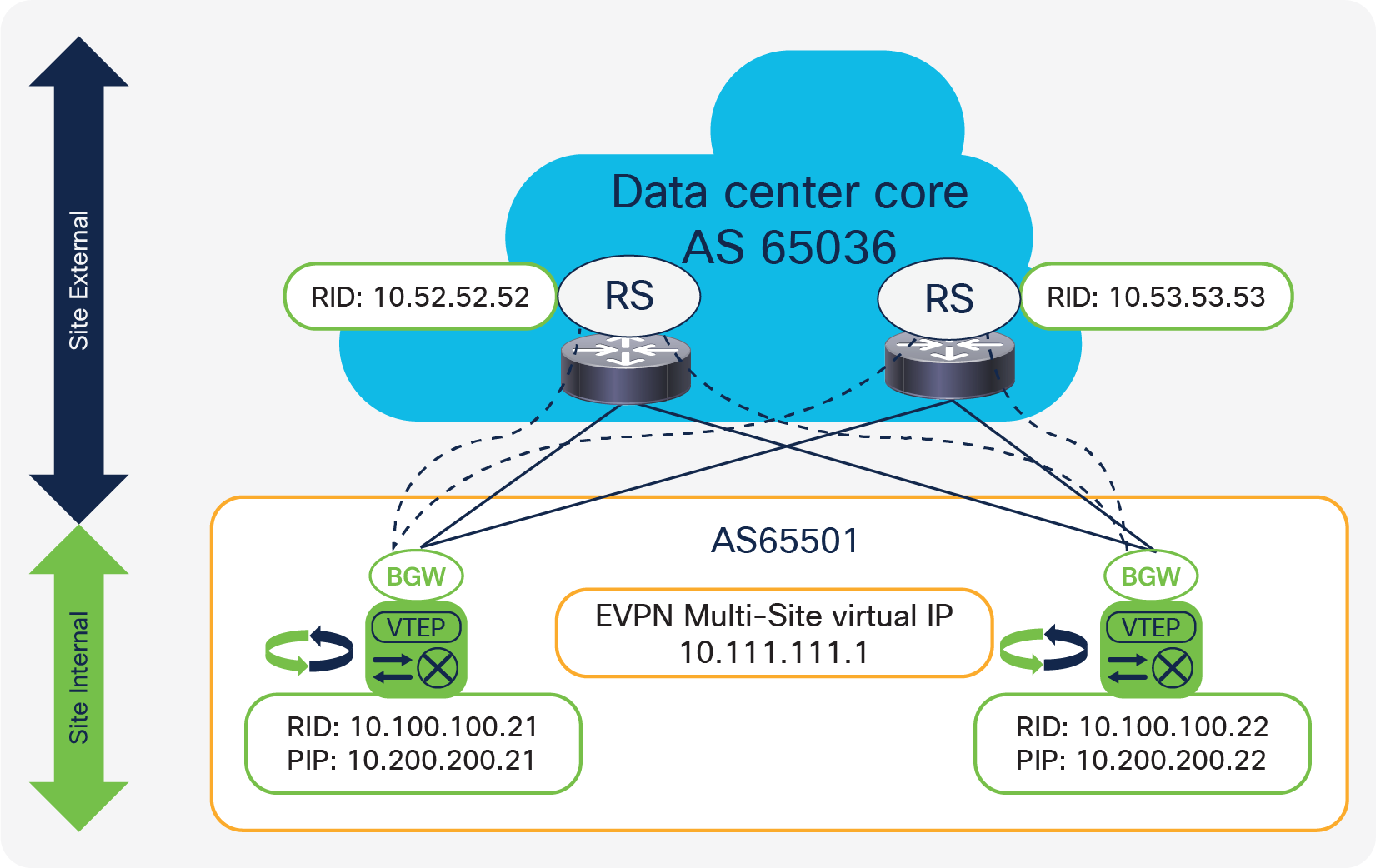
A common choice is to deploy the BGWs at the border of the fabric with the border leaf and DCI node functions. The BGW-to-cloud model (Figure 10) has a redundant Layer 3 cloud between the different sites. In this deployment model, the Layer 3 cloud provides to each site redundant connectivity points to which the BGWs can connect. Assuming four BGWs and two data center core devices, full-mesh connectivity can be established among them all, using the basic principle of building triangles, not squares. Similar connectivity can be achieved by the other sites, so that every BGW has redundant connectivity to the Layer 3 cloud, which also reduces the convergence time in a link-failure scenario.
The only specific requirements for the Layer 3 cloud are that it provide IP connectivity between the virtual IP and PIP addresses of the BGWs and accommodate the MTU for the VXLAN-encapsulated traffic across the cloud. The Layer 3 cloud can be any routed service, such as a flat Layer 3 routed network, a Multiprotocol Label Switching (MPLS) Layer 3 VPN (L3VPN), or other provider services. Whenever a VPN-like service is provided in the Layer 3 cloud, note that the physical interfaces on the BGW site must remain in the default VRF instance. Multiprotocol-BGP (MP-BGP) peering with VPN address families is supported only as part of the default VRF instance.
If a deployment consists of many sites and many BGWs, the need for full-mesh eBGP peerings between any BGWs for the overlay control plane may create additional complexity. The introduction of a Route Server (RS) can simplify the design and reduce the burden of having so many BGP peerings. A BGP route server is basically an eBGP route reflector, which in BGP terminology doesn’t exist. A BGP route server performs the same route reflection function as an iBGP route reflector. Neither type of reflector needs to be in the data path to perform this function. Such a route server can be placed in the Layer 3 cloud or in a separate location reachable from every BGW. The route server will act as a star point for all the control-plane peerings for all the BGWs and will help ensure reflection of BGP updates. For resiliency, a pair of route servers is recommended.
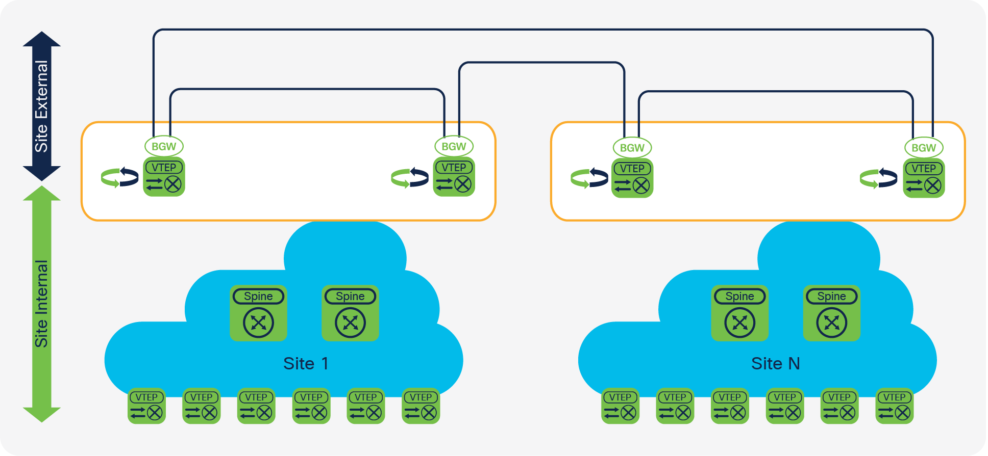
BGW back-to-back model
The back-to-back connectivity model (Figure 11) provides an alternative to the topology in which the BGWs are connected to a Layer 3 cloud. For the back-to-back topology, you need to consider how the BGWs are interconnected within the site and between sites. In addition to physical-connectivity issues, you need to consider scenarios such as link failure, designated-forwarder reelection, and BUM-traffic forwarding (especially in a failure scenario).
Assuming two BGWs per site, the back-to-back connectivity model builds a square between the two BGWs at the local site and the two BGWs at the remote site. A permutation of this topology is a square with an additional cross between the BGWs, which is slightly more resilient and does not require designated-forwarder reelection if a single link fails. The Layer 3 underlay between all BGWs is achieved with a point-to-point subnet and the advertisement of the virtual IP and PIP addresses of the BGWs into this routing domain.
Note: The minimum back-to-back topology, the square, will not provide ECMP for fast convergence and traffic depolarization. In the extended back-to-back topology, with the square plus the full mesh between the BGWs, ECMP is available.
The only specific requirements for back-to-back connectivity are that it provide IP connectivity between all virtual IP and PIP addresses for the BGWs and accommodate the MTU for the VXLAN-encapsulated traffic across the links.
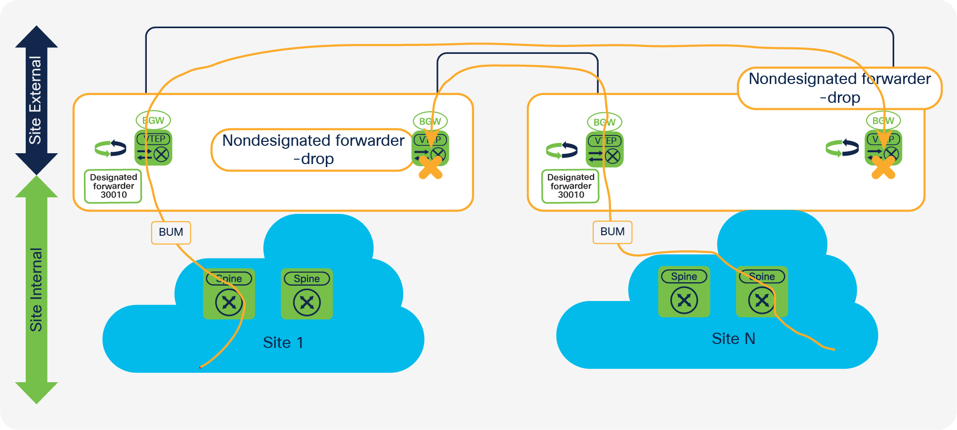
BGW back-to-back model (BUM traffic not acceptable)
The minimum back-to-back topology is a square. The connection between the BGWs in the same site allows proper BUM-traffic handling during normal operations and failure scenarios, without requiring designated-forwarder reelection. In a square topology, in which the designated forwarder at the local site is connected to the nondesignated-forwarder spine at the remote site, BUM traffic cannot be forwarded to the remote site without the link between the BGW at the same site (Figure 12). The compensation link between the site-local BGWs allows BUM traffic to be forwarded flawlessly. The link between the BGWs can be considered a backup path to the remote site and can be configured with DCI tracking enabled (Figure 13).
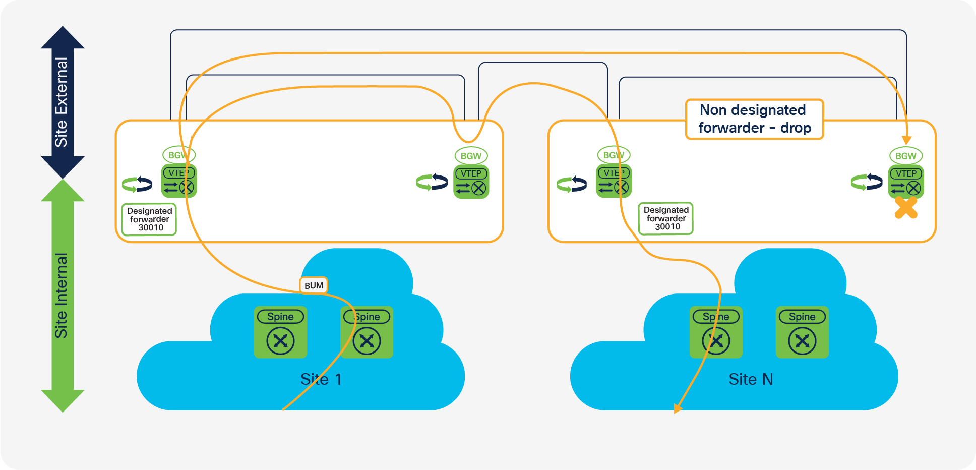
BGW back-to-back model (BUM traffic acceptable)
Note: BUM replication between sites will always include in the replication list all BGWs with the respective destination Layer 2 VNIs.
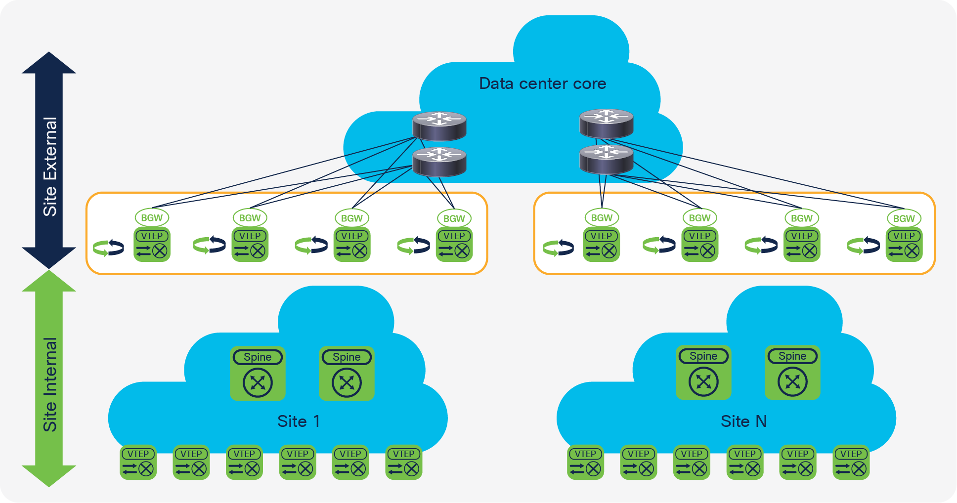
Model with BGW between spine and superspine
The model in which the BGWs are placed between the spine and superspine (Figure 14) is similar to the BGW-to-cloud scenario. With a spine-and-leaf folded Clos model creating the site-internal network, the BGWs are placed on top of the spine. The superspine layer is part of the site-external network. With all the BGWs of the various sites connected to the superspine, you achieve a topology with the same network layers as in the BGW-to-cloud model. The main difference is in the geographical radius of such a topology. Whereas the BGW-to-cloud approach considers the Layer 3 cloud to be extended across a long distance, the superspine likely exists within a physical data center. With the superspine model, all BGWs of all sites connect to all superspines. This approach creates a high-speed backbone within a data center, also known as the data center core.
Model with BGWs between spine and superspine
The deployment of the BGWs between the spine and superspine presents a deployment use case different from the DCI use case. With the BGWs between the spine and superspine, data center fabrics are scaled by interconnecting them in a hierarchical fashion. The achievement here is not simply extension of connectivity across fabrics. This approach also uses the masking that EVPN Multi-Site architecture provides to reduce the amount of peering between all VTEPs and thus to increase scale. With EVPN Multi-Site architecture and the BGWs, you can compartmentalize functional building blocks within the data center. The easy interconnection of these compartments is achieved through the integrated Layer 2 and Layer 3 extension provided by EVPN Multi-Site architecture. With selective control-plane advertisement and the enforcement of BUM traffic at the BGWs, you can achieve more control over extension between fabrics.
As with the BGW-to-cloud approach, the use of a BGP route server can be beneficial when you deploy BGWs between the spine and superspine. With many sites and many BGWs per site, the number of peering can easily grow dramatically. The route-server approach allows you to rein in the control-plane exchanges between all the BGWs across sites with a simplified peering model.
The previous topologies used dedicated BGW nodes. In the BGW-on-spine model (Figure 15), the BGW is co-located with the spine of the site-internal network (fabric). When the BGW and spine are combined, the exit points of the fabric and the spine are on the same set of network nodes. You thus need to consider, for example, how leaf-to-leaf communication occurs and how BGW-to-BGW communication occurs.
BGW-on-spine model
For the site-internal VTEP or leaf-to-leaf communication, the traffic pattern is through the BGW and spine combination. Also, the services that a leaf requires are reachable through one hop at the BGW and spine.
BGW-to-BGW communication is less natural. For example, consider the designated-forwarder election exchange. The BGW and spine don’t have any direct connection or BGP peering between them, so the control-plane exchange to synchronize the BGWs must be achieved through additional iBGP peering (full mesh). In this design, the only path available for the designated-forwarder exchange between the BGWs is through the site-internal VTEPs (leaf nodes). Although this approach doesn’t create any problems from a traffic volume or a resiliency perspective, the use of a control-plane exchange between the BGW traversing the leaf node is not natural.
The main functional component of the EVPN Multi-Site architecture consists of the BGW devices. Their deployment affects the way that the overlay network performs its Layer 2 and Layer 3 services. Given that stability is of paramount importance for the overlay, proper design of the underlay network is critical.
For EVPN Multi-Site architecture, numerous best practices and recommendations have been established to successfully deploy the overall solution. This document focuses mainly on two main models for the underlay. It also discusses the overlay.
● The I-E-I model focuses on an Interior Gateway Protocol (IGP) and iBGP (IGP-iBGP)–based site-internal network (fabric) with eBGP-eBGP at the external site (DCI).
● The E-E-E model uses eBGP-eBGP within the site (fabric) as well as between sites (DCI).
Note: Although Cisco supports both models, the I-E-I deployment scenario is recommended. For additional information about the E-E-E deployment model and why I-E-I is the recommended approach, see the “For more information” section at the end of this document.
The two models can be mixed in the sense that one site can run on “E” (eBGP-eBGP) and the other, remote site can run on “I” (IGP-iBGP). From an intersite underlay, eBGP can be replaced with any routing protocol, as long as a clean separation exists between the site-internal and site-external routing domains. As described later in this section, the “E” (eBGP) portion for the overlay is mandatory.
In addition to choosing the underlay routing protocols, you must separate the site-internal and site-external routing domains. In the case of I-E-I, the underlays will not likely be redistributed between the “I” (IGP) and the “E” (eBGP) domains. Furthermore, you must actively separate the site-internal underlay from the site-external underlay in the E-E-E case, because by default BGP automatically exchanges information between the underlay domains. In cases in which the site-internal and site-external underlays are joined, unanticipated forwarding and failure cases may occur.
The following sections present the main design principles for successfully deploying the EVPN Multi-Site architecture. The two primary topologies discussed here are the BGW-to-cloud model and the model with the BGW between the spine and superspine.
Site-internal underlay (fabric)
The site-internal underlay can be deployed in various forms. Most commonly, an IGP is used to provide reachability between the intrasite VTEP (leaf), the spine, and the BGWs. Alternative approaches for underlay unicast reachability use BGP; eBGP with dual- and multiple-autonomous systems are known designs.
For BUM replication, either multicast (PIM ASM) or ingress replication can be used. EVPN Multi-Site architecture allows both modes to be configured. It also allows different BUM replication modes to be used at different sites. Thus, the local site-internal network can be configured with ingress replication while the remote site-internal network can be configured with a multicast-based underlay.
Note: BGP EVPN allows BUM replication based on either ingress replication or multicast (PIM ASM). The use of EVPN doesn’t preclude the use of a network-based BUM replication mechanism such as multicast.
BGW: Site-internal OSPF underlay
Figure 16 shows the BGW with a site-internal topology.
BGW with site-internal topology
The configuration for a BGW with a site-internal OSPF underlay is shown here.
| version 7.0(3)I7(1) |
This version is the minimum software release required for EVPN Multi-Site architecture. |
| feature ospf |
Enable feature ospf for underlay IPv4 unicast routing. |
| feature pim |
Enable feature pim for multicast-based BUM replication. Note: This setting is not required if ingress replication is used for the intrasite underlay. |
| router ospf UNDERLAY router-id 10.100.100.21 |
Define the OSPF process tag and OSPF router ID. Note: The OSPF router ID matches the loopback0 IP address. |
| interface loopback0 description RID AND BGP PEERING ip address 10.100.100.21/32 tag 54321 ip router ospf UNDERLAY area 0.0.0.0 ip pim sparse-mode |
Define the loopback0 interface for the routing protocol router ID and overlay control-plane peering (that is, BGP peering). The IP address is extended with a tag to allow easy selection for redistribution. The OSPF process tag is used for site-internal underlay routing. Note: The ip pim sparse-mode setting is needed only for intrasite multicast-based BUM replication. |
Note: The loopback interface used for the router ID and BGP peering must be advertised to the site-internal underlay as well as to the site-external underlay. If deemed beneficial, separate loopback interfaces can be used for site-internal and site-external purposes as well as for the various routing protocols (router ID, peering, etc.).
| interface loopback1 description NVE INTERFACE (PIP VTEP) ip address 10.200.200.21/32 tag 54321 ip router ospf UNDERLAY area 0.0.0.0 ip pim sparse-mode |
Define the loopback1 interface as the NVE source interface (PIP VTEP). The IP address is extended with a tag to allow easy selection for redistribution. The OSPF process tag is used for site-internal underlay routing. Note: The ip pim sparse-mode setting is needed only for intrasite multicast-based BUM replication. |
Note: The loopback interface used for the individual VTEP (PIP) must be advertised to the site-internal underlay as well as to the site-external underlay.
| Interface loopback100 description MULTI-SITE INTERFACE (VIP VTEP) ip address 10.111.111.1/32 tag 54321 ip router ospf UNDERLAY area 0.0.0.0 |
Define the loopback100 interface as the EVPN Multi-Site source interface (anycast and virtual IP VTEP). The IP address is extended with a tag to allow easy selection for redistribution. The OSPF process tag is used for site-internal underlay routing. |
Note: The loopback interface used for the EVPN Multi-Site anycast VTEP (virtual IP address) must be advertised to the site-internal underlay as well as to the site-external underlay.
| Interface Ethernet1/53 description SITE-INTERNAL INTERFACE no switchport mtu 9216 medium p2p ip address 10.1.1.34/30 ip ospf network point-to-point ip router ospf UNDERLAY area 0.0.0.0 ip pim sparse-mode evpn multisite fabric-tracking
interface Ethernet1/54 description SITE-INTERNAL INTERFACE no switchport mtu 9216 medium p2p ip address 10.1.2.34/30 ip ospf network point-to-point ip router ospf UNDERLAY area 0.0.0.0 ip pim sparse-mode evpn multisite fabric-tracking |
Define site-internal underlay interfaces facing the spine. Adjust the MTU value for the interface to accommodate your environment (minimum value is 1500 bytes plus VXLAN encapsulation). You can use point-to-point IP addressing or IP unnumbered addressing (IP unnumbered support started in 7.0(3)I7(2)) for site-internal underlay routing (point-to-point IP addressing with /30 is shown here). Specify the OSPF network type (point to point) and OSPF process tag for site-internal underlay routing. Note: The ip pim sparse-mode setting is needed only for site-internal multicast-based BUM replication. Specify EVPN Multi-Site interface tracking for the site-internal underlay (evpn multisite fabric-tracking). This command is mandatory to enable the Multi-Site virtual IP address on the BGW. At least one of the physical interfaces that are configured with fabric tracking must be up to enable the Multi-Site BGW function (keeping the virtual IP VTEP address active). |
The site-internal overlay for VXLAN BGP EVPN always behaves like an iBGP deployment, whereas the underlay can use eBGP. This is the case regardless of whether a single-autonomous-system, dual-autonomous-system, or multiple-autonomous-system design is used. For a single-autonomous-system deployment, the overlay control-plane configuration is straightforward. For a dual- or multiple-autonomous-system design, additional BGP configurations are needed. This document focuses on EVPN Multi-Site architecture, so the site-internal overlay configuration for dual- and multiple-autonomous-system designs is omitted. For configuration guidance for dual- and multiple-autonomous-system designs, see the “For more information” section at the end of this document.
Note: If BGP EVPN control-plane communication between BGWs traverses a site-internal BGP route reflector, the route reflector must support BGP EVPN Route Type 4. If the route reflector doesn’t support BGP EVPN Route Type 4, direct BGW-to-BGW full-mesh iBGP peering must be configured. BGP EVPN Route Type 4 is used for EVPN Multi-Site designated-forwarder election.
BGW: Site-internal iBGP overlay
The configuration for a BGW with a site-internal iBGP overlay is shown here.
| version 7.0(3)I7(1) |
This version is the minimum software release required for EVPN Multi-Site architecture. |
| feature bgp |
Enable feature bgp for underlay IPv4 unicast routing. |
| feature nv overlay nv overlay evpn |
Enable feature nv overlay for VXLAN VTEP capability. Extend the capability of VXLAN with EVPN (nv overlay evpn). |
| evpn multisite border-gateway <site-id> delay-restore time 300 |
Define the node as an EVPN Multi-Site BGW with the appropriate site ID. Note: All BGWs at the same site must have the same site ID (site ID 1 is shown here). As a subconfiguration of the BGW definition, a time-delayed restore operation for BGW virtual IP address advertisement can be set. |
| interface nve1 host-reachability protocol bgp source-interface loopback1 multisite border-gateway interface loopback100 |
Define the NVE interface (VTEP) and extend it with EVPN (host-reachability protocol bgp). Define the loopback1 interface as the NVE source interface (PIP VTEP). Define the loopback100 interface as the EVPN Multi-Site source interface (anycast and virtual IP VTEP). |
| router bgp 65501 neighbor 10.100.100.201 remote-as 65501 update-source loopback0 address-family l2vpn evpn send-community send-community extended
neighbor 10.100.100.202 remote-as 65501 update-source loopback0 address-family l2vpn evpn send-community send-community extended |
Define the BGP routing instance with a site-specific autonomous system. Note: The BGP router ID matches the loopback0 IP address. Define the neighbor configuration with the EVPN address family (L2VPN EVPN) for the site-internal overlay control plane facing the route reflector. Configure the iBGP neighbor by specifying the source interface loopback0. This setting allows underlay ECMP reachability from BGW loopback0 to route-reflector loopback0. |
The site-external underlay is the network that interconnects multiple VXLAN BGP EVPN fabrics. It is a transport network that allows reachability between all the EVPN Multi-Site BGWs and external VTEPs. Some deployment scenarios use an additional spine tier (superspine), and other deployments have a routed Layer 3 cloud.
The site-external underlay network can be deployed with various routing protocols, but eBGP is typically used to provide reachability between the BGWs of multiple sites, given its interdomain nature. Alternative approaches for underlay reachability include the use of IGP, but this document focuses solely on eBGP.
For BUM replication between sites, EVPN Multi-Site architecture exclusively uses ingress replication to simplify the requirements of the site-external underlay network.
Note: Ingress replication to handle BUM replication between sites (site-external network) doesn’t limit the use of the available BUM replication mode to a given site (site-internal network). EVPN Multi-Site architecture allows the use of multicast (PIM ASM) for BUM replication within one site, while other sites can use ingress replication or multicast.
BGW: Site-external eBGP underlay
Figure 17 shows the BGW with a site-external topology.
BGW with site-external topology
The configuration for a BGW with a site-external eBGP underlay is shown here.
| version 7.0(3)I7(1) |
This version is the minimum software release required for EVPN Multi-Site architecture. |
| feature bgp |
Enable feature bgp for underlay IPv4 unicast routing. |
| interface Ethernet1/1 no switchport mtu 9216 ip address 10.52.21.1/30 tag 54321 evpn multisite dci-tracking
interface Ethernet1/2 no switchport mtu 9216 ip address 10.53.21.1/30 tag 54321 evpn multisite dci-tracking |
Define site-external underlay interfaces facing the external Layer 3 core. Adjust the MTU value of the interface to accommodate your environment (the minimum value is1500 bytes plus VXLAN encapsulation). Point-to-point IP addressing is used for site-external underlay routing (point-to-point IP addressing with /30 is shown here). The IP address is extended with a tag to allow easy selection for redistribution. Note: The ip pim sparse-mode setting is not needed because site-external BUM replication always uses ingress replication. EVPN Multi-Site interface tracking is used for the site-external underlay (evpn multisite dci-tracking). This command is mandatory to enable the Multi-Site virtual IP address on the BGW. At least one of the physical interfaces that are configured with DCI tracking must be up to enable the Multi-Site BGW function. |
| route-map RMAP-REDIST-DIRECT permit 10 match tag 54321 |
The route map is used to select all IP addresses that are attached to an interface and that carry the tag extension. |
| router bgp 65501 router-id 10.100.100.21 log-neighbor-changes address-family ipv4 unicast redistribute direct route-map RMAP-REDIST-DIRECT maximum-paths 4 |
Define the BGP routing instance with a site-specific autonomous system. Note: The BGP router ID matches the loopback0 IP address. Activate the IPv4 unicast global address family (VRF default) to redistribute the required loopback and physical interface IP addresses within BGP. Enable BGP multipathing (maximum-paths). Note: The redistribution from the locally defined interfaces (direct) to BGP is performed through route-map classification. Only IP addresses in the VRF default instance that are extended with the matching tag of the route map are redistributed. |
| neighbor 10.52.21.2 remote-as 65036 update-source Ethernet1/1 address-family ipv4 unicast
neighbor 10.53.21.2 remote-as 65036 update-source Ethernet1/2 address-family ipv4 unicast |
The neighbor configuration for the IPv4 unicast global address family (VRF default) facilitates site-external underlay routing. Configure the eBGP neighbor by selecting the source interface for this eBGP peering. |
The site-external overlay for VXLAN BGP EVPN must use eBGP, because the eBGP next-hop behavior is used for VXLAN tunnel termination and reorigination.
In the case of EVPN Multi-Site architecture, a site-internal MAC address or IP prefix advertisement originates from the local BGWs with their anycast VTEPs as the next hop. Similarly, the BGWs of the local site receive a MAC address or IP prefix advertised from remote BGWs with their anycast VTEPs as the next hop. This behavior follows eBGP’s well-known and proven process of changing the next hop at the autonomous system boundary. EVPN Multi-Site architecture uses eBGP not only for VXLAN tunnel termination and reorigination, but also for its loop prevention mechanism offered through the as-path attribute. With this approach, on the control plane, prefixes originating at one site will never be imported back into the same site, thus preventing routing loops. On the data plane, designated-forwarder election and split-horizon rules complement the control-plane loop-prevention functions.
Note: BGP EVPN control-plane communication between BGWs at different sites can be achieved using either a full mesh or a route server (eBGP route reflector).
BGW: Site-external eBGP overlay
The configuration for a BGW with a site-external eBGP overlay is shown here.
| version 7.0(3)I7(1) |
This version is the minimum software release required for EVPN Multi-Site architecture. |
| feature bgp |
Enable feature bgp for underlay IPv4 unicast routing. |
| feature nv overlay nv overlay evpn |
Enable feature nv overlay for the VXLAN VTEP capability. Extend VXLAN with EVPN (nv overlay evpn). |
| evpn multisite border-gateway <site-id> delay-restore time 300 |
Define the node as an EVPN Multi-Site BGW with the appropriate site ID. Note: All BGWs at the same site must have the same site IDs (site ID 1 is shown here). As a subconfiguration of the BGW definition, a time-delayed restore operation for BGW virtual IP address advertisement can be set. |
| interface nve1 host-reachability protocol bgp source-interface loopback1 multisite border-gateway interface loopback100 |
Define the NVE interface (VTEP) and extend it with EVPN (host-reachability protocol bgp). Define the loopback1 interface as the NVE source interface (PIP VTEP). Define the loopback100 interface as the EVPN Multi-Site source interface (anycast and virtual IP VTEP). |
Note: Feature enablement and VXLAN, BGP EVPN, and EVPN Multi-Site global configuration have already been described in the “BGW: Site-internal iBGP overlay”.
| router bgp 65501 router-id 10.100.100.21 log-neighbor-changes
neighbor 10.52.52.52 remote-as 65036 update-source loopback0 ebgp-multihop 5 peer-type fabric-external address-family l2vpn evpn send-community send-community extended rewrite-evpn-rt-asn
neighbor 10.53.53.53 remote-as 65036 update-source loopback0 ebgp-multihop 5 peer-type fabric-external address-family l2vpn evpn send-community send-community extended rewrite-evpn-rt-asn |
Define the BGP routing instance with a site-specific autonomous system. Note: The BGP router ID matches the loopback0 IP address. Configure the neighbor with the EVPN address family (L2VPN EVPN) for the site-external overlay control plane facing the route server or remote BGW (peering to a pair of route servers is shown here). Configure the eBGP neighbor by specifying the source interface loopback0. This setting allows underlay ECMP reachability from BGW loopback0 to route-server loopback0. Note: Site-external EVPN peering is always considered to use eBGP with the next hop the remote site BGWs. With the route server or remote BGW potentially multiple routing hops away, you must increase the BGP session Time-To-Live (TTL) setting to an appropriate value (ebgp-multihop). In defining the site-external BGP peering session (peer-type fabric external), rewrite and reorigination are enabled. (This function is explained in detail in the upcoming section “Site-external route server”. The autonomous system portion of the automated route target (ASN:VNI) will be rewritten upon receipt from the site-external network (rewrite-evpn-rt-asn) without modification of any configurations on the site-internal VTEPs. The route-target rewrite will help ensure that the ASN portion of the automated route target matches the destination autonomous system. |
Route server (eBGP route reflector)
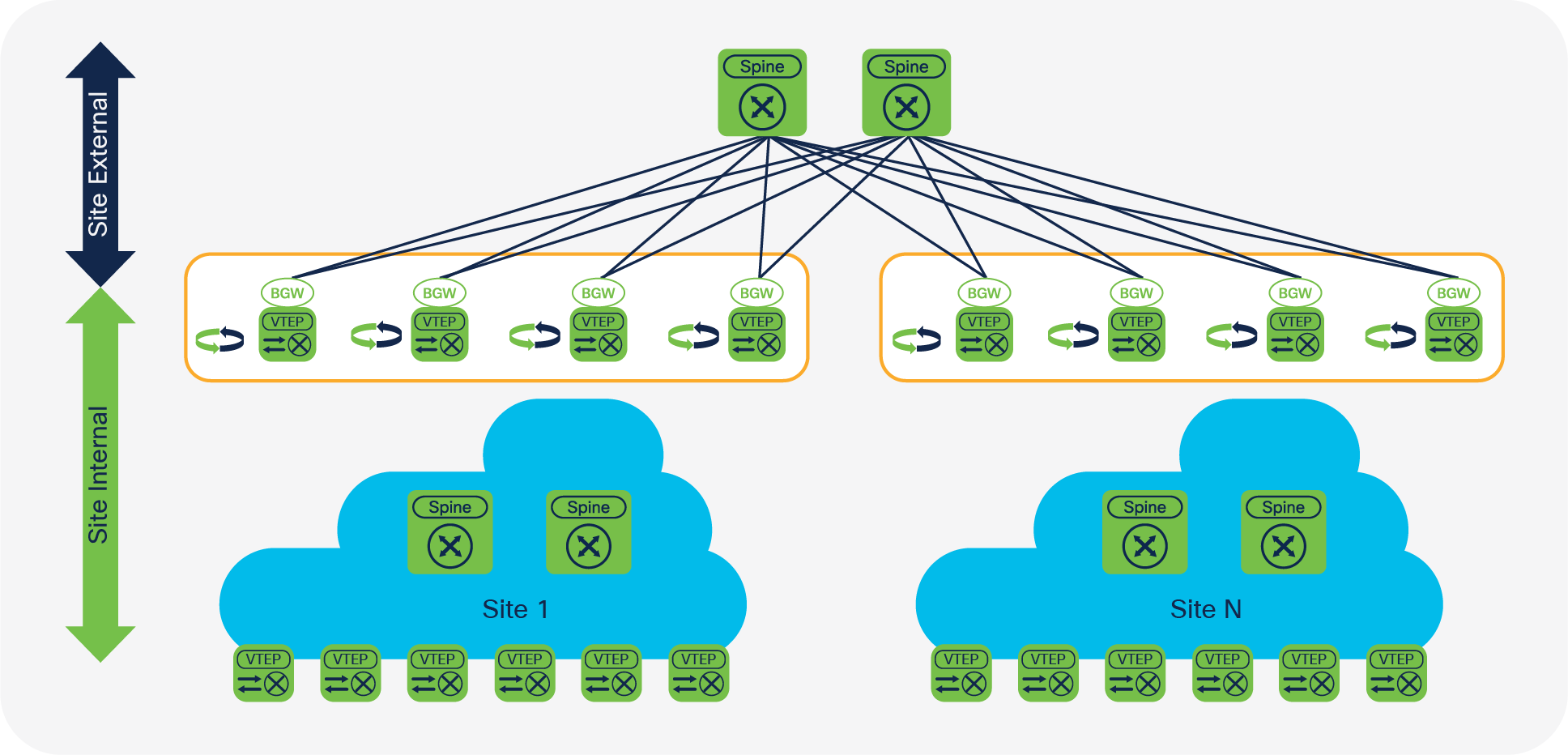
EVPN Multi-Site architecture requires every BGW from a local site to peer with every BGW at remote sites. This full-mesh requirement is not mandatory for a proper exchange of information in a steady-state environment, but given the various failure scenarios that are possible, a full mesh is the recommended configuration (Figure 18). When you deploy two sites with two BGWs in each topology, the number of BGP peerings remains manageable. However, when you scale out the EVPN Multi-Site environment and add more sites and BGWs to each site, the number of full-mesh BGP peerings becomes difficult to manage and creates a burden on the control plane.
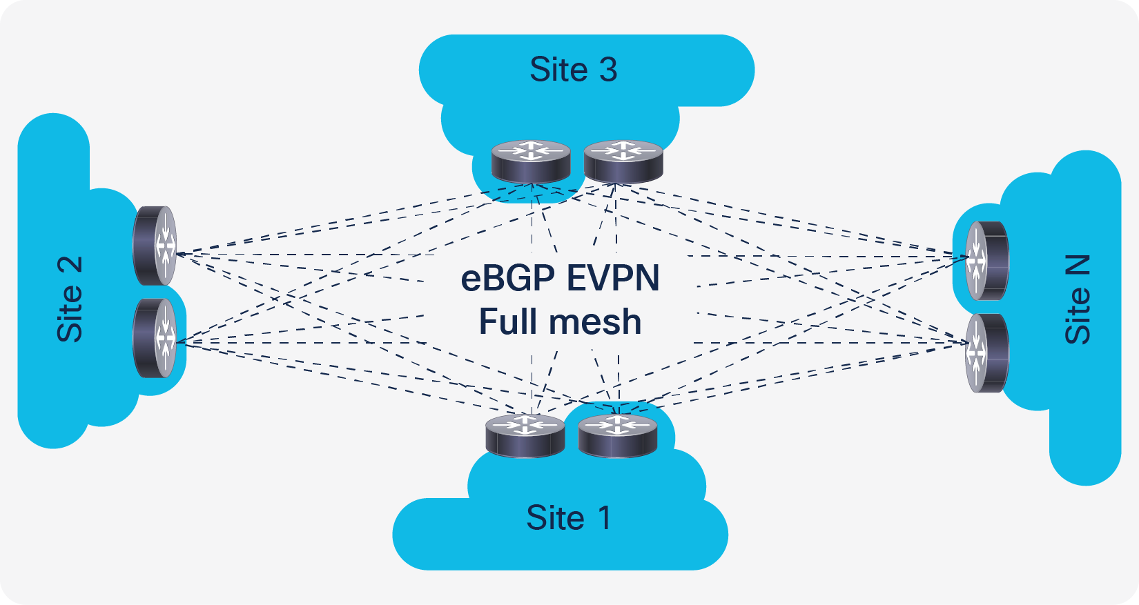
EVPN Multi-Site without route server
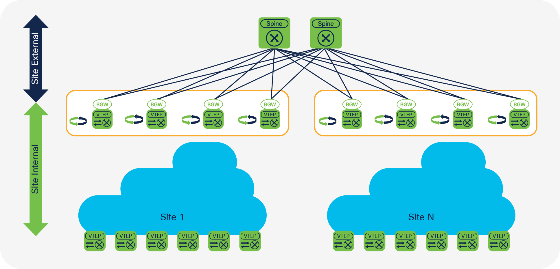
A more elegant approach to a scale-out EVPN Multi-Site environment is to use a star point to broker the site-external overlay control plane (Figure 19). Such nodes are well known in iBGP environments as route reflectors. They are present to reflect routes that are being sent from their clients that don’t require a full mesh anymore. This approach allows the environment to scale well from control-plane peering, and it also eases the management burden of configuration and operation. BGP route reflectors are limited to providing their services to iBGP-based peering. In the case of eBGP networks, the route-reflector function is absent or nonexistent. However, for eBGP networks, a function similar to the route-reflector function is offered by the route server, as described in IETF RFC 7947: Internet Exchange BGP Route Server.
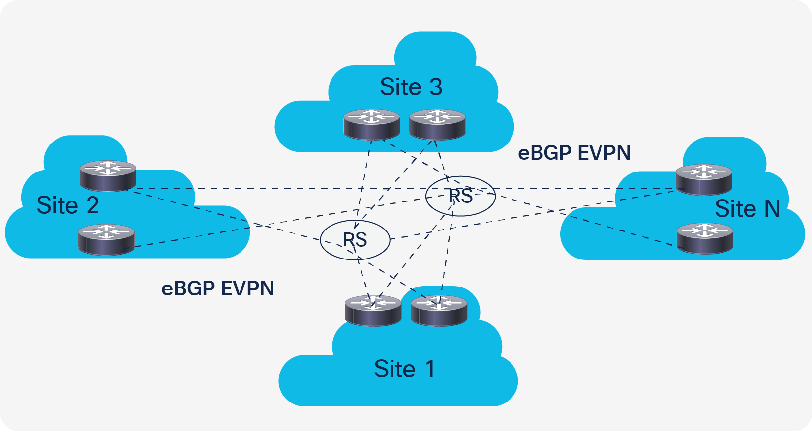
EVPN Multi-Site with route server
Like a route reflector, a route server performs a pure control-plane function and doesn’t need to be in the data path between any of the BGWs. To help ensure that the route-server deployment provides resiliency for the EVPN Multi-Site control-plane exchange in any failure scenario, connectivity or device redundancy is required. Various platforms support the configuration of a route server in either a hardware-only or software-only design. Cisco NX-OS offers the route-server capability in the Cisco Nexus Family switches, which can be connected on a stick or within the data path as a node for the site-external underlay. The route server must be able to support the EVPN address family, reflect VPN routes, and manipulate the next-hop behavior (next-hop unchanged). In addition, the route server should support route-target rewrite to simplify the deployment.
The configuration for a site-external route server is shown here.
| feature bgp |
Enable feature bgp for underlay IPv4 unicast routing. |
| route-map UNCHANGED permit 10 set ip next-hop unchanged |
The route map enforces the policy to leave the overlay next hop unchanged when the route server is used. Note: The route server is not a VTEP or BGW and hence should not have the next hop pointing to itself. |
| router bgp 65036 address-family l2vpn evpn retain route-target all |
Define the BGP routing instance with a site-independent autonomous system. You must ensure that all the received EVPN advertisements are reflected even if all the tenant VRF instances are not created on the route server. The route targets must be preserved while that function is performed (retain route-target all). |
| template peer OVERLAY-PEERING update-source loopback0 ebgp-multihop 5 address-family l2vpn evpn send-community both route-map UNCHANGED out |
The per-neighbor configuration for the overlay control-plane function in a route server can be simplified. The configuration of the BGP reachability function across multiple hops (ebgp-multihop) and preservation of the next hop between the BGWs are common settings. These configuration knobs, including the source interface, can be combined in a BGP peer template. Note: BGP peer templates are part of the BGP instance configuration. |
| neighbor 10.100.100.21 remote-as 65501 inherit peer OVERLAY-PEERING address-family l2vpn evpn rewrite-evpn-rt-asn
neighbor 10.100.100.22 remote-as 65501 inherit peer OVERLAY-PEERING address-family l2vpn evpn rewrite-evpn-rt-asn
neighbor 10.101.101.41 remote-as 65520 inherit peer OVERLAY-PEERING address-family l2vpn evpn rewrite-evpn-rt-asn
neighbor 10.101.101.42 remote-as 65520 inherit peer OVERLAY-PEERING address-family l2vpn evpn rewrite-evpn-rt-asn |
Configure the neighbor in the IPv4 unicast global address family (VRF default) to peer with the site-external loopback interface (loopback0) of the BGW. Configure the eBGP neighbor by using BGP peer templates and activating the EVPN address family (address family L2VPN EVPN). The autonomous system portion of the automated route target (ASN:VNI) will be rewritten upon receipt from the site-external network (rewrite-evpn-rt-asn) without modification of any configuration on the site-internal VTEPs. If a route server stands in between the BGWs of the individual sites, an additional rewrite to the destination autonomous system is performed. The route-target rewrite helps ensure that the ASN portion of the automated route target matches the destination autonomous system. |
Note: The use of a route server is optional, but it simplifies the EVPN Multi-Site deployment.
Previous configuration sections mentioned the capability to rewrite the automated route-target macros.
In VXLAN EVPN, Cisco NX-OS uses an automated route-target derivation in which a prefix is followed by a 2-byte Autonomous System Number (ASN). The suffix of the route target is populated with the VNI, which has a total size of 4 bytes. The prefix portion with the ASN is derived from the BGP instance that is locally configured on the respective node, and the VNI is derived from either the Layer 2 or Layer 3 configuration and its use depends on whether a MAC or IP address import must be performed. Table 2 shows an example.
Table 2. Sample route-target prefix and suffix
| Prefix |
Suffix |
| 2-byte ASN |
4-byte VNI |
| 65501 |
50000 |
When the MP-BGP and VPN address families are used, the route target defines what is imported into a given VRF instance. The route target is defined based on the export configuration of the VRF instance in which the prefix was learned. The route target is attached to the BGP advertisement as an extended community to the prefix itself. At the remote site, the import configuration of the VRF instance defines the route-target extended community that is matched and the information that is imported.
In EVPN Multi-Site architecture, each site is defined as an individual BGP autonomous system. Thus, with the use of automated route targets, the configurations of the VRF instance and the route-target extended community potentially diverge. For instance, if the local site uses ASN 65501 and the remote site uses ASN 65520, the route targets will be misaligned, and no prefixes learned from the control plane will be imported.
To allow the site-internal configuration to use the automated route target and require no change to any VTEP, the rewriting of the autonomous system portion on the route target must be possible, because the export route target at the local site must match the import route target at the remote site. In EVPN Multi-Site architecture, the route target can be rewritten during ingress at the remote site.
The autonomous system portion of the route target will be rewritten with the ASN specified in the BGP peering configuration. This action allows, for example, route-target 65501:50000 at the local site to be rewritten as 65520:50000 upon receipt of the BGP advertisements at the BGW of the remote site. If a route server is between the BGWs, additional route-target rewrite must be performed on the route server. In this case, for example, route-target 65501:50000 at the local site can be rewritten as 65036:50000 on the route server and then as 65520:50000 at the remote site. This example assumes a symmetric VNI deployment (the same VNI across sites).
This approach enables successful export and import route-target matching by using automated route-target derivation with route-target rewrite. Neither the existing VTEP configuration or the static route-target configuration needs to be changed.
The route-target rewrite function is performed on the EVPN Multi-Site BGW facing the site-external overlay peering.
Note: As of Cisco NX-OS 7.0(3)I7(1), automated route-target derivation and route-target rewrite are limited to a 2-byte ASN. This limitation as a result of the route-target format (ASN:VNI) used, which allows space for a 2-byte prefix (ASN) with a 4-byte suffix (VNI). In cases in which a 4-byte ASN is required, you can use common route targets across sites.
Peer-type fabric-external function
Whereas the route-target rewrite function is an optional configuration to simplify the deployment, the definition of site-external overlay peering on the EVPN Multi-Site BGW is mandatory.
EVPN Multi-Site architecture adds the function that enables intermediate nodes, the BGWs, to terminate and reoriginate VXLAN encapsulation at Layer 2 and Layer 3. In BGP EVPN–based overlay networks, the control plane defines what the data plane and VXLAN use to build adjacencies, for example. The EVPN Multi-Site architecture is based on IETF draft-sharma-multi-site-evpn.
IETF RFC-7432 and draft-ietf-bess-evpn-overlay, draft-ietf-bess-evpn-prefix-advertisement, and draft-ietf-bess-evpn-inter-subnet-forwarding specify that BGP EVPN Route Type 2 and Route Type 5 carry the Router MAC (RMAC) address of the next hop’s VTEP (Table 3). EVPN Multi-Site architecture masks the original advertising VTEP (usually a local leaf node) behind the BGW, and hence the RMAC must match the BGW in between rather than the advertising VTEP. The introduction of the peer-type fabric-external function helps ensure that the advertised VTEP IP information is properly rewritten (virtual IP address) and that the RMAC address present in EVPN Route Type 2 and Route Type 5 matches the virtual MAC address of the BGW. With the implementation of this function, every IETF RFC and draft conforming VTEP can peer with a BGW either site internal or site external without specifically needing to have EVPN Multi-Site BGW capabilities.
Note: Cisco NX-OS follows the following implementation as defined by IETF RFC-7342, draft-ietf-bess-evpn-overlay, draft-ietf-bess-evpn-prefix-advertisement, and draft-ietf-bess-evpn-inter-subnet-forwarding.
Table 3. IETF specifications for EVPN Multi-Site architecture
| RFC or draft |
|
|
| RFC-7432 |
VLAN-based service interface BGP EVPN routes |
Section 6.1 Section 7 |
| draft-ietf-bess-evpn-overlay |
Encapsulation options |
Section 5 |
| draft-ietf-bess-evpn-prefix-advertisement |
Interface-less IP-VRF-to-IP-VRF advertisement |
Section 4.4.1 |
| draft-ietf-bess-evpn-inter-subnet-forwarding |
Symmetric intersubnet forwarding |
Section 5 |
To successfully peer with an EVPN Multi-Site BGW, RFC and draft conformity must be achieved, and a common BUM replication mode must be used. Supported site-internal BUM replication modes are multicast (PIM ASM) and ingress replication. The supported site-external BUM replication mode is ingress replication.
Previous sections discussed EVPN Multi-Site design scenarios and underlay and overlay configurations. This section explores the configurations needed for the VNIs, for either Layer 2 or Layer 3 extension. This section also discusses how to limit the extension, from either the control plane (selective advertisement) or data plane (BUM enforcement).
This section begins by exploring the name-space mapping for VNIs and the use of VNIs across multiple sites with EVPN Multi-Site architecture.
EVPN Multi-Site architecture allows the extension of Layer 2 and Layer 3 segments beyond a single site. Using EVPN Multi-Site architecture, you can extend Layer 2 VNIs to enable seamless endpoint mobility and address other use cases that require communication bridged beyond a single site. Use cases involving Layer 3 extension beyond a single site primarily require multitenant awareness or VPN services. With the multitenant capability in BGP EVPN and specifically in EVPN Multi-Site architecture, multiple VRF instances or tenants can be extended beyond a single site using a single control plane (BGP EVPN) and a single data plane (VXLAN).
All the use cases for EVPN Multi-Site architecture have the name space provided by VXLAN—the VXLAN network identifier, or VNI—as a central feature. This 24-bit name space, with about 16 million potential identifiers, is an integral part of VXLAN and is used by VXLAN BGP EVPN and EVPN Multi-Site architecture.
As of Cisco NX-OS 7.0(3)I7(1) for the Cisco Nexus 9000 Series EX- and FX-platform switches, all deployed sites must follow a consistent assignment of VNIs for either Layer 2 or Layer 3 extension. Therefore, a VLAN or VRF instance at the local site must be mapped to the same VNI that is used at the remote site. This consistent mapping is called symmetric VNI assignment. Subsequent releases will expand this capability to enable asymmetric VNI assignment, in which different VNIs can be stitched together at the BGW level.
With the use of Layer 2 and Layer 3 extension to facilitate endpoint mobility, the boundaries of hierarchical addressing are nonexistent. Thus, an individual endpoint’s MAC address and host IP address must be seen within a site or across sites whenever bridging communication is required. The host IP address is not especially important for the bridging itself, but it is needed to provide optimal routing between endpoints. To help ensure that endpoints in different IP subnets can communicate without hairpinning through a remote site, knowledge of the /32 and /128 host routes is crucial.
EVPN Multi-Site architecture not only facilitates these Layer 2 and Layer 3 extension use cases, but it also provides ways to optimize such environments, building hierarchical networks even when Layer 2 extension is needed. EVPN Multi-Site selective advertisement limits the control-plane advertisements on the BGW depending on the presence of per-tenant configurations. If a VRF instance is configured on the BGW to allow a multitenant-aware Layer 3 extension, the data plane is configured, and control-plane advertisement in BGP EVPN is enabled. With this approach, only after the VRF instance is configured and associated with the VTEP is the relevant IP host and IP subnet prefix information advertised to the site-external network. The same approach is followed for Layer 2 extension and MAC address advertisement, with advertisements sent to the site-external network only after the Layer 2 segment has been configured and associated with the VTEP.
These advertisement control functions are provided simply to keep the site-external network manageable and to prevent saturation of the control-plane tables with unnecessary entries. In addition, if VRF route-target imports are configured unintentionally, the selective advertisement approach helps preserve hardware table space on the BGW and even on the VTEPs beyond it.
Selective advertisement is implicitly enabled. Control-plane advertisements are limited based on the local VRF and VNI configurations on the BGWs.
The configuration to enable Layer 3 extension through an EVPN Multi-Site BGW closely follows the configuration for a normal VTEP. However, for an EVPN Multi-Site BGW, no endpoint-facing Layer 2 or Layer 3 configuration is defined. All the per-tenant configuration settings for Layer 3 are provided solely to allow VXLAN traffic termination and reencapsulation for transit through the BGW. The configuration used for the BGW transit functions also facilitates the selective advertisement control explained in the previous section.
Note: All BGWs at a given site must have the same configurations for Layer 3 extensions.
| vlan 2003 vn-segment 50001 |
Define the Layer 3 VNI and attach it to a BGW local VLAN. Note: The VLAN ID has no significance for any endpoint-facing function. It is a resource allocation setting only. |
| vrf context BLUE vni 50001 rd auto address-family ipv4 unicast route-target both auto route-target both auto evpn address-family ipv6 unicast route-target both auto route-target both auto evpn |
Define a VRF context (IP VRF) with the appropriate instance name. The Layer 3 VNI chosen refers to the vn-segment ID chosen in the previous step. The route distinguisher for the IP VRF instance can be derived automatically by using the router ID followed by the internal VRF ID (RID:VRF-ID). Similarly, the route target can be derived automatically by using the BGP autonomous system followed by the VNI defined as part of the VRF instance (ASN:VNI). The route targets must be enabled for the IPv4/IPv6 address family and specifically for EVPN. Note: The use of the automated route distinguisher and route target is optional, but it is a best practice. |
| interface loopback 51 vrf member BLUE ip address 10.55.55.1/32 |
Note: In cases where only Layer 3 extension is configured on the BGW an additional loopback interface is required. The loopback interface must be present in the same VRF instance on all BGW and with an individual IP address per BGW. Ensure the loopback interfaces IP address is redistributed into BGP EVPN, specially towards Site-External. |
| interface Vlan2003 mtu 9192 vrf member BLUE no ip redirects ip forward ipv6 forward no ipv6 redirects |
Define a Layer 3 interface to enable the previously defined VNI to become a fully functional Layer 3 VNI. Verify that the MTU accommodates your needs and that the forwarding matches the IPv4/IPv6 requirements. Note: The SVI identifier must match the identifier that was chosen earlier. The VRF member name must match the VRF context name in the next step. |
| interface nve1 member vni 50001 associate-vrf |
Associate the Layer 3 VNI with the NVE interface (VTEP) and associate it with the VRF type. |
Note: In addition to configuring the Layer 3 extension, you may need to add the VRF information in the configuration of the BGP instance. This step is mandatory if external connectivity for locally connected devices is required.
As with Layer 3 extension, the configuration to enable Layer 2 extension through an EVPN Multi-Site BGW is similar to the configuration used for a normal VTEP. However, for an EVPN Multi-Site BGW, no endpoint-facing Layer 2 or Layer 3 configuration is defined (that is, no distributed IP anycast gateway). All the Layer 2 configuration settings are provided solely to help ensure VXLAN traffic termination and reencapsulation for transit through the BGW only. The configuration for Layer 2 extension also promotes selective advertisement beyond the BGW.
Note: All BGWs for a given site must have the same configuration for Layer 2 extensions.
| vlan 10 vn-segment 30010 |
Define the Layer 2 VNI and attach it to a BGW local VLAN. Note: The VLAN ID has no significance for any endpoint-facing function. It is a resource allocation setting only. |
| interface nve1 member vni 30010 multisite ingress-replication [ingress-replication protocol bgp] [mcast-group 239.1.1.0] |
Associate the Layer 2 VNI with the NVE interface (VTEP) and configure the relevant site-internal and site-external BUM replication modes (dual mode). Note: Site-external BUM replication always uses ingress replication. Site-internal BUM replication can use multicast (PIM ASM) or ingress replication. Note: Configure only one site-internal BUM replication mode: either multicast (PIM ASM) or ingress replication. |
| evpn vni 30010 l2 rd auto route-target import auto route-target export auto |
Define a VRF context (MAC VRF instance) with the appropriate Layer 2 VNI and the forwarding mode (L2). The Layer 2 VNI chosen refers to the vn-segment ID chosen in the previous step. The route distinguisher of the MAC VRF instance can be derived automatically by using the router ID followed by the internal VRF ID (RID:VRF-ID). Similarly, the route target can be derived automatically by using the BGP autonomous system followed by the VNI defined as part of the VRF instance (ASN:VNI). The route targets must be enabled for the IPv4/IPv6 address family and specifically for EVPN. Note: The use of an automated route distinguisher and route target is optional, but it is a best practice. |
Note: As of Cisco NX-OS 7.0(3)I7(1) for the Cisco Nexus 9000 Series EX- and FX-platform switches, local endpoint connectivity is not supported on an EVPN Multi-Site BGW.
Layer 2 extension is a common use case. It is also a scenario in which failure replication is largely exposed. To provide a safer approach for Layer 2 extension, EVPN Multi-Site architecture allows you to control Layer 2 BUM traffic leaving the local site. EVPN Multi-Site architecture uses separate flood domains for site-internal and site-external traffic. This approach allows you to filter traffic between the flood domains. It also introduces split-horizon rules to help ensure that traffic entering the BGW from one flood domain does not return to the same flood domain. If BUM traffic reaches the BGW from the site-internal network, forwarding is allowed only to the site-external network, and if BUM traffic reaches the BGW from the site-external network, forwarding is allowed only to the site-internal network.
EVPN Multi-Site architecture allows selective rate limiting for BUM traffic classes that are known to saturate network infrastructure during broadcast storms, loops, and other traffic-generating failure scenarios. The BGW provides the capability to enforce these traffic classes individually through a rate limiter. Only traffic leaving the local site following termination and reorigination within the BGW will be enforced. The BUM enforcement takes place before the traffic is reoriginated on the BGW for transmission to a remote site.
As of Cisco NX-OS 7.0(3)I7(1) for the Cisco Nexus 9000 Series EX- and FX-platform switches, the classification and rate limiting are applied globally to each BGW. The configured rate-limiting level represents the amount of BUM traffic allowed from each interface that faces the site-external network.
| evpn storm-control broadcast level 0-100 evpn storm-control multicast level 0-100 evpn storm-control unicast level 0-100 |
Define storm control for EVPN Multi-Site Layer 2 extension. The percentage can be adjusted from 0% (block all classified traffic) to 100% (allow all classified traffic). Note: The classification and use of storm control for EVPN Multi-Site architecture is comparable to that for storm control on a physical Layer 2 interface. |
In an EVPN Multi-Site environment, the requirement for external connectivity is as relevant as the requirement for extension between sites. External connectivity includes the connection of the data center to the rest of the network: to the Internet, the WAN, or the campus. All options provided for external connectivity are multitenant aware and focus on Layer 3 transport to the external network domains.
This document discusses two models for providing external connectivity to EVPN Multi-Site architecture:
● With the placement of the BGWs at the border between the site-internal and site-external domains, a set of nodes is already available at each site that can provide encapsulation and decapsulation for transit traffic. In addition to the EVPN Multi-Site functions, the BGW allows coexistence of VRF-aware connectivity with VRF-lite.
● In addition to per-BGW or per-site external connectivity, connectivity can be provided through a shared border. In this case, a dedicated set of border nodes are placed at the site-external portion of multiple sites. All of these sites connect through VXLAN BGP EVPN to this shared border set, which then provides external connectivity. The shared-border approach also allows MPLS L3VPN, LISP, or VRF-lite hand-off to multiple sites.
VXLAN BGP EVPN provides optimal egress route optimization using the distributed IP anycast gateway function at every VTEP. This optimization is achieved by equipping every VTEP with a first-hop gateway and the information needed to take the best path to a given destination.
With stretched IP subnets across multiple sites, the explicit location of a subnet becomes unclear, and more granular information must be provided in the routing tables. Both the external connectivity models mentioned here allow ingress route optimization by VXLAN BGP EVPN through host-route advertisement (/32 and /128).
In the shared-border model, additional ingress route optimization can be applied depending on the platform used. This topic is discussed in greater detail in the “Shared border” section.
The VRF-lite coexistence model (Figure 20) uses the traditional approach to providing external connectivity to a VXLAN BGP EVPN fabric. In particular, this model uses the approach of interautonomous system option A, in which the site-internal network uses MP-BPG with VPN address families. Interautonomous system option A requires the presence of a route distinguisher and route target, although in VRF-lite these would not normally be necessary. For the purposes here, this document uses the terms “VRF-lite” and “interautonomous system option A” interchangeably. For external connectivity, the use of physical Layer 3 interfaces is preferred, with each interface in a separate VRF instance. To use multiple VRF instances on a single physical Layer 3 interface, the use of subinterfaces is recommended.
Note: The EVPN Multi-Site BGW with VRF-lite coexistence is supported starting NX-OS 7.0(3)I7(3)
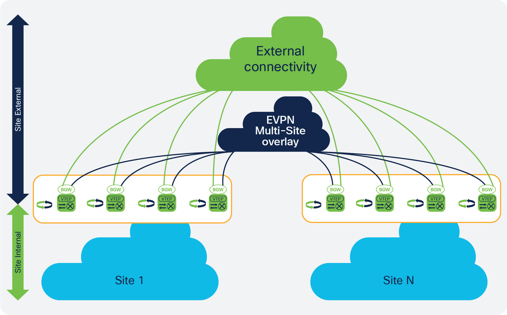
VRF-lite coexistence
Note: The EVPN Multi-Site BGW does not support the coexistence of external connectivity with IEEE 802.1q tagged Layer 2 interfaces (trunk) and SVIs (interface VLAN), either with or without vPC. More generally, SVIs cannot currently be defined on the BGW.
Because BGP is already in use for EVPN and EVPN Multi-Site architecture, it is the recommended option for exchanging routing information with external routers (VRF-lite external connectivity with the use of a subinterface). Dynamic routing protocols and static routing can also be used, but as a best practice the eBGP approach for VRF-lite coexistence on the BGW is preferred. The physical Layer 3 interface for external connectivity must be dedicated and can’t be shared with the site-external connectivity for EVPN Multi-Site architecture.
| vrf context BLUE vni 50001 rd auto address-family ipv4 unicast route-target both auto route-target both auto evpn address-family ipv6 unicast route-target both auto route-target both auto evpn |
Verify that the VRF context (IP VRF instance) with the appropriate instance name has been prepared. The correct Layer 3 VNIs, address families, and route targets must be defined to allow the site-internal VTEPs to have external connectivity. Note: For the external connectivity, interautonomous system option A and route distinguishers and route targets are required for the site-internal VXLAN BGP EVPN control plane. |
Note: Selective advertisement is defined by the configuration of the per-tenant information on the BGW. In cases in which external connectivity (VRF-lite) and EVPN Multi-Site architecture both are active on the same BGW, the advertisements are always enabled. If this behavior is not desired, you should consider using a dedicated border for external connectivity and EVPN Multi-Site architecture.
| interface Ethernet1/3.4 encapsulation dot1q 4 vrf member BLUE ip address 10.55.21.1/30 |
Define a Layer 3 subinterface associated with the previously defined VRF, with a point-to-point subnet and IEEE 802.1q tag (VLAN id). This interface connects to the external router. Note: The VLAN ID and point-to-point subnet must match the neighboring interface. The subinterface ID doesn’t need to match the VLAN ID, but consistency is recommended to simplify troubleshooting. |
| router bgp 65501 vrf BLUE |
Define the VRF instance in the BGP instance. |
| address-family ipv4 unicast advertise l2vpn evpn |
Extend the VRF instance in the BGP instance with the IPv4/IPv6 unicast address family and enable it for EVPN. Note: The IPv6 unicast address family is not shown, but it follows same configuration process. |
| neighbor 10.55.21.2 remote-as 65099 update-source Ethernet1/3.4 address-family ipv4 unicast |
Create the eBGP peering with the neighbor autonomous system and the relevant source interface. Enable the IPv4 unicast address family for this peering. Note: The IPv6 unicast address family is not shown, but it follows the same configuration process. |
In addition to using route peering to the external router through eBGP, you may sometimes want to advertise the default route to the fabric. Two methods are used to advertise the default route to the fabric:
● The default route is learned through eBGP from the external router on a per-VRF basis. This default route is automatically passed through the BGW and advertised to the site-internal VTEPs through BGP EVPN.
● The default route is learned through a static or dynamic routing protocol (not eBGP). This approach requires the BGW to locally originate the default route and inject it into the BGP EVPN control plane facing the site-internal VTEPs.
Figure 21 shows both approaches.
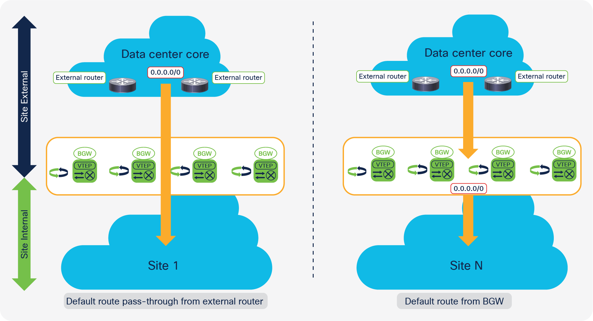
Default route: External router versus BGW
The first method requires some route filtering to prevent the fabric from becoming a transit network, but no additional configuration is required to receive and advertise the default route to the site-internal VTEPs.
The following configuration example focuses on the second method, using a static route to the external router. The route-filtering configuration example covers both methods.
| vrf context BLUE ip route 0.0.0.0/0 10.55.21.2 |
Define a static default route to the next-hop IP address of the external router in the appropriate VRF instance. Note: The default route can also be received through a dynamic routing protocol. |
| ip prefix-list DEFAULT-ROUTE seq 5 permit 0.0.0.0/0 le 1 |
Define a prefix list that matches the default route. |
| route-map EXTCON-RMAP-FILTER deny 10 match ip address prefix-list DEFAULT-ROUTE |
Define a route map that matches the prefix list, and prevent that match from being advertised to the external connectivity. Note: The default route should be advertised only to the site-internal VTEPs. |
| route-map EXTCON-RMAP-FILTER permit 1000 |
Extend the route map to allow everything that does not match the previous definitions. |
| router bgp 65501 vrf BLUE address-family ipv4 unicast network 0.0.0.0/0 |
Define a network statement to advertise the default route to BGP. Because this route is originated locally or learned remotely, it will become an EVPN Route Type 5 route for the site-internal VTEPs. |
| neighbor 10.55.21.2 remote-as 65099 update-source Ethernet1/3.4 address-family ipv4 unicast route-map EXTCON-RMAP-FILTER out |
Attach the route filter to the external connectivity peering facing the external router. Note: Without the route filter, the VXLAN BGP EVPN fabric can accidentally become a transit network for traffic external to the fabric. |
If a single EVPN Multi-Site instance loses external connectivity, but other sites still have external connectivity, EVPN Multi-Site Layer 2 and Layer 3 extension will be used to reach external connectivity for remote sites. If this approach is deemed not beneficial, you can filter external connectivity routes between EVPN Multi-Site fabrics.
In addition to preventing the VXLAN BGP EVPN fabric from becoming a transit network, you can introduce use another optimization through route filtering. The advertisement of host routes (/32 and /128) is performed by default in VXLAN BGP EVPN. This default behavior can be altered by suppressing the host routes with route summarization at the border facing the external domain or through route filtering (Figure 22).
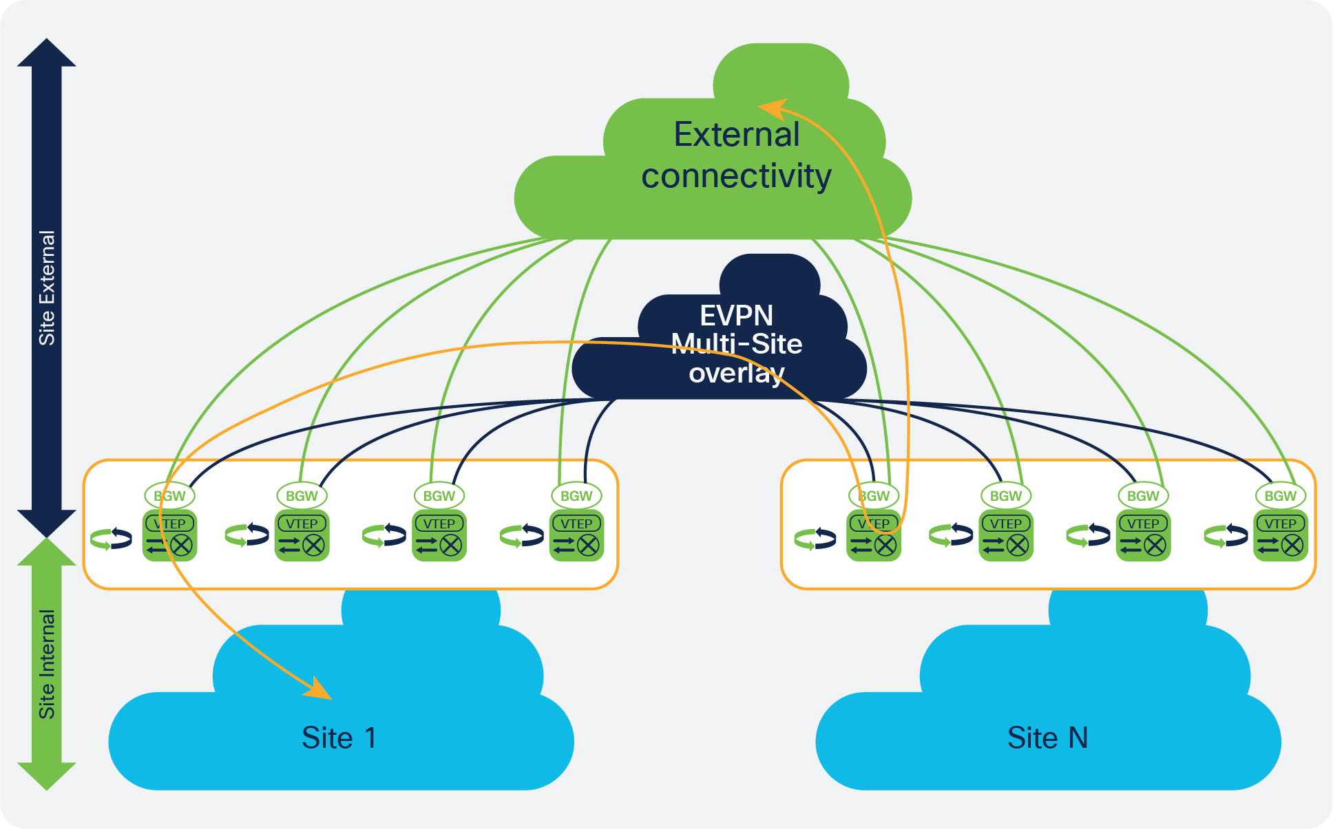
External connectivity through EVPN Multi-Site
Using the same constructs of the prefix list and route map, you can suppress host routes as shown in the following configuration.
| ip prefix-list HOST-ROUTE seq 5 permit 0.0.0.0/0 eq 32 |
Define a prefix list that matches all the host routes. Note: IPv6 host-route filtering can be achieved in a similar way. |
| route-map EXTCON-RMAP-FILTER deny 20 match ip address prefix-list HOST-ROUTE |
Define a route map that matches the prefix list, and prevent that match from being advertised to the external connectivity. Note: This route map is an extension of the one previously created for the default route filtering. |
| route-map EXTCON-RMAP-FILTER permit 1000 |
Extend the route map to allow everything that did not match the previous definitions. |
As a result of the external connectivity configuration, you can route to an external domain, preventing the VXLAN BGP EVPN fabric from becoming a transit network and suppressing host-route advertisements. By disabling host-route advertisements, however, you are not using optimal ingress route optimization. You need to consider this fact when stretching an IP subnet across multiple VXLAN EVPN sites that are extended with EVPN Multi-Site architecture, because ingress routing will then choose any BGW that advertises external connectivity.
Note: The suppression of host routes is not supported between VXLAN BGP EVPN sites that are connected with EVPN Multi-Site architecture. This is specifically the case for the EVPN Multi-Site Layer 2 extension.
The shared border acts as a common external connectivity point for multiple VXLAN BGP EVPN fabrics that are interconnected with EVPN Multi-Site architecture. Unlike the BGW, the shared border is completely independent of any VXLAN EVPN Multi-Site software or hardware requirements, it is solely a border node topologically outside of a single or multiple Sites. The shared border operates like a traditional VTEP, but unlike the site-internal VTEPs discussed previously, the shared border is a site-external VTEP. In the case of external connectivity, the shared border operates solely in Layer 3 mode, and hence no BUM replication between the BGW and shared border nodes is necessary. What you must configure on the shared border is the VXLAN BGP EVPN VTEP and its presence in a different autonomous system than the one that includes the BGWs.
The shared border can enable external connectivity with various Layer 3 technologies, depending on hardware and software capabilities. Some examples are Cisco Nexus 9000 Series Switches (VRF-lite), Cisco Nexus 7000 Series Switches (VRF-lite, MPLS L3VPN, and LISP), Cisco ASR 9000 Series Aggregation Services Routers (VRF-lite and MPLS L3VPN), and Cisco ASR 1000 Series routers (VRF-lite and MPLS L3VPN). This document focuses on the required configuration of the BGW that connects to the shared border. Configuration knobs required on the shared border are discussed, but not the various Layer 3 hand-off technologies for external connectivity.
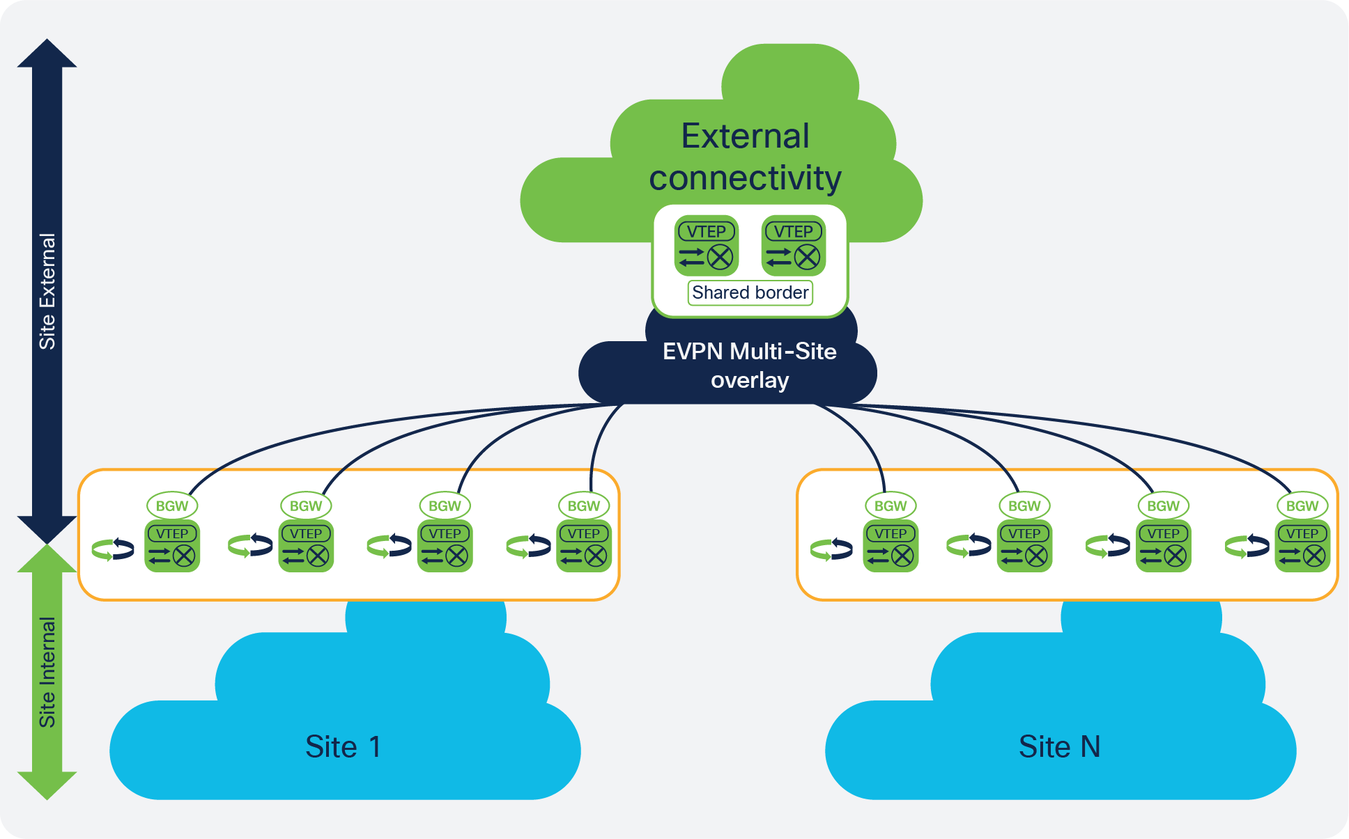
EVPN Multi-Site shared border
For an EVPN Multi-Site BGW to connect with a shared border, it requires a configuration similar to that for connecting the gateway to the BGW of a remote site (Figure 23). Unlike the EVPN Multi-Site site-external underlay configuration, the configuration of the interface facing the shared border nodes doesn’t require interface tracking. It is specifically not necessary to influence the availability of the EVPN Multi-Site virtual IP address, because if the shared border becomes absent, no external routes can be advertised to the site-internal network.
The configuration presented here shows the site-external underlay and overlay configuration on a BGW. The underlay between the BGW and the shared border must be reachable, specifically between the loopback interfaces that provide the VTEP and the overlay peering function. The VXLAN BGP EVPN connectivity between the BGW and the shared border requires a physical Layer 3 interface, as previously discussed for EVPN Multi-Site architecture. For the BGW-to-cloud, BGW-between-spine-and-superspine, and BGW-on-spine deployment models, the existing EVPN Multi-Site site-external underlay interfaces can be used to reach the shared border. When choosing between shared and dedicated external connectivity interfaces, note that you also need to consider your needs for bandwidth and additional resiliency.
BGW to shared border: Site-external eBGP underlay
The configuration for a BGW to a shared border with a site-external eBGP underlay is shown here.
| interface Ethernet1/3 no switchport mtu 9216 ip address 10.55.41.1/30 tag 54321 |
Define site-external underlay interfaces facing the external Layer 3 core with the shared border present. Adjust the MTU setting for the interface to a value that accommodates your environment (the minimum value is 1500 bytes plus VXLAN encapsulation). Point-to-point IP addressing is used for site-external underlay routing (point-to-point IP addressing with /30 is shown here). The IP address is extended with a tag to allow easy selection for redistribution. Note: No EVPN Multi-Site interface tracking (evpn multisite dci-tracking) is required for the site-external underlay facing the shared border. |
| router bgp 65520 router-id 10.101.101.41 address-family ipv4 unicast redistribute direct route-map RMAP-REDIST-DIRECT maximum-paths 4 |
Define the BGP routing instance with a site-specific autonomous system. Note: The BGP router ID matches the loopback0 IP address. Activate the IPv4 unicast global address family (VRF default) to redistribute the required loopback and, if needed, the IP addresses of the physical interfaces within BGP. Enable BGP multipathing (maximum-paths). Note: The redistribution from the locally defined interfaces (direct) into BGP is performed through route-map classification. Only IP addresses in VRF default that are extended with the matching tag of the route map are redistributed. |
| neighbor 10.55.41.2 remote-as 65099 update-source Ethernet1/3 address-family ipv4 unicast |
Configure the neighbor for the IPv4 unicast global address family (VRF default) to facilitate site-external underlay routing. eBGP neighbor configuration is performed by specifically selecting the source interface for this eBGP peering. |
BGW to shared border: Site-external eBGP overlay
The configuration for a BGW to a shared border with a site-external eBGP overlay is shown here.
| router bgp 65520 router-id 10.100.100.41 log-neighbor-changes
neighbor 10.55.55.55 remote-as 65099 update-source loopback0 ebgp-multihop 5 peer-type fabric-external address-family l2vpn evpn send-community send-community extended rewrite-evpn-rt-asn |
Define the BGP routing instance with a site-specific autonomous system. Note: The BGP router ID matches the loopback0 IP address. Configure the neighbor with the EVPN address family (L2VPN EVPN) for the site-external overlay control plane facing the shared border. eBGP neighbor configuration is performed by specifying the source interface to loopback0. This setting allows underlay ECMP reachability from BGW loopback0 to shared-border loopback0. Note: Site-external EVPN peering is always considered to use eBGP with the next hop the shared border. With the shared border potentially multiple routing hops away, you must increase the BGP session TTL setting to an appropriate value (ebgp-multihop). When you define the site-external BGP peering session (peer-type fabric external), rewrite and reorigination are enabled. The autonomous system portion of the automated route target (ASN:VNI) can be rewritten for the site-external network (rewrite-evpn-rt-asn) without the need to modify any configuration settings on the shared border. The route-target rewrite helps ensure that the ASN portion of the automated route target matches the destination autonomous system. |
To provide some context for the configuration for a shared border, the following sample shows the settings required to exchange overlay information. The underlay must be reachable between the BGW and the shared border: specifically between the loopback interfaces that provide the VTEP and the overlay peering function.
Shared border to BGW: eBGP underlay
The configuration for a shared border to a BGW with an eBGP underlay is shown here.
| interface Ethernet1/3 mtu 9216 ip address 10.55.41.2/30 tag 54321 |
Define site-external underlay interfaces facing the external Layer 3 core with the BGW present. Adjust the MTU setting for the interface to a value that accommodates your environment (the minimum value is 1500 bytes plus VXLAN encapsulation). Point-to-point IP addressing is used for site-external underlay routing (point-to-point IP addressing with /30 is shown here). The IP address is extended with a tag to allow easy selection for redistribution. |
| router bgp 65099 address-family ipv4 unicast redistribute direct route-map RMAP-REDIST-DIRECT maximum-paths 4 |
Define the BGP routing instance with a shared-border-specific autonomous system. Note: The BGP router ID matches the loopback0 IP address. Activate the IPv4 unicast global address family (VRF default) to redistribute the required loopback and, if needed, the IP addresses of the physical interfaces within BGP. Enable BGP multipathing (maximum-paths). Note: The redistribution from the locally defined interfaces (direct) to BGP is performed through route-map classification. Only IP addresses in VRF default that are extended with the matching tag of the route map are redistributed. |
| neighbor 10.55.41.1 remote-as 65520 update-source Ethernet1/3 address-family ipv4 unicast |
The neighbor configuration for the IPv4 unicast global address family (VRF default) facilitates shared-border underlay routing. The eBGP neighbor configuration is performed by specifically selecting the source interface for this eBGP peering. |
Shared border to BGW: eBGP overlay
The configuration of a shared border to a BGW with an eBGP overlay is shown here.
| router bgp 65099 address-family ipv4 unicast redistribute direct route-map RMAP-REDIST-DIRECT maximum-paths 4
neighbor 10.101.101.41 remote-as 65520 update-source loopback0 ebgp-multihop 5 address-family l2vpn evpn rewrite-evpn-rt-asn send-community both |
Define the BGP routing instance with a site-specific autonomous system. Configure the neighbor with the EVPN address family (L2VPN EVPN) for the site-external overlay control plane facing the BGW. eBGP neighbor configuration is performed by specifying the source interface to loopback0. This setting allows underlay ECMP reachability from BGW loopback0 to shared-border loopback0. Note: Site-external EVPN peering is always considered to use eBGP with the next hop the BGW. With the BGW potentially multiple routing hops away, you must increase the BGP session TTL setting to an appropriate value (ebgp-multihop). The autonomous system portion of the automated route target (ASN:VNI) can be rewritten for the site-external network (rewrite-evpn-rt-asn) without the need to modify any configuration settings on the BGWs. The route-target rewrite helps ensure that the ASN portion of the automated route target matches the destination autonomous system. |
Note: In the shared-border deployment, the BGW of every site must have connectivity to the shared border. Otherwise, routes that VXLAN BGP EVPN learns from a shared border to a BGW will not be advertised to remote sites because the shared border and the remote site BGWs are considered site-external devices.
| interface loopback 51 vrf member BLUE ip address 10.55.55.1/32 |
Note: In cases where only Layer 3 extension is configured on the BGW, special in the case of Shared Border, an additional loopback interface is required. The loopback interface must be present in the same VRF instance on all BGW and with an individual IP address per BGW. Ensure the loopback interfaces IP address is redistributed into BGP EVPN, specially towards Site-External. |
For migration and integration purposes, existing non-VXLAN BGP EVPN sites (legacy sites) require connectivity with VXLAN BGP EVPN sites. For integration, a Layer 3–only connectivity model can be used. This approach would allow routing exchange between the different networks, similar to the external connectivity approach through VRF-lite. Depending on the VRF awareness and number of VRF instances, this option can be acceptable, but the configuration complexity will increase with the number of VRF instances. If Layer 2 extension with same IP subnet between the legacy site and VXLAN EVPN is required, the complexity and dependencies increase, and you must consider IEEE 802.1q trunks for Layer 2 extension, VRF-aware routing for Layer 3, and first-hop gateway consistency.
VXLAN EVPN Multi-Site architecture simplifies legacy site integration and consistently provides the required Layer 2 and Layer 3 extension. Alternative approaches are documented as part of multifabric designs and EVPN–to–Overlay Transport Virtualization (OTV) interoperation solutions. For details, see the “For more information” section at the end of this document.
Similar to the process in the shared-border scenario, the integration of a legacy site is achieved by positioning a set of VTEPs external to the VXLAN BGP EVPN sites (a pair of vPC BGWs). The attributes for a site-external VTEP for such an integration are similar to those for a BGW (VXLAN BGP EVPN, ingress replication for BUM, BUM control, etc.), with the addition of a classic Ethernet multihoming approach (vPC) to connect to the legacy network infrastructure (Figure 24).
Note: vPC is not required by the EVPN Multi-Site architecture but is needed to provide resilient and loop-free connectivity to the legacy site.
Special considerations for Layer 2 extensions apply to BUM control and failure isolation, because the legacy site BGW (vPC BGWs) uses some different (and simplified) configurations given the absence of site-internal VTEPs. The EVPN Multi-Site BUM enforcement feature can be useful. You can apply storm control on the VPC BGW Ethernet interfaces connecting to the site-internal switches. This traditional approach works, but does not allow you to enforce BUM control in an aggregated way. Depending on the number of connections to the legacy network, the BGW may end up allowing more BUM traffic than is desired across the EVPN Multi-Site overlay. When using the BUM enforcement feature within the legacy site BGW, you can enforce aggregated rate limiting based on the well-known BUM traffic classes. This approach allows simpler deployment as well as additional control right before traffic traverses the EVPN Multi-Site overlay.
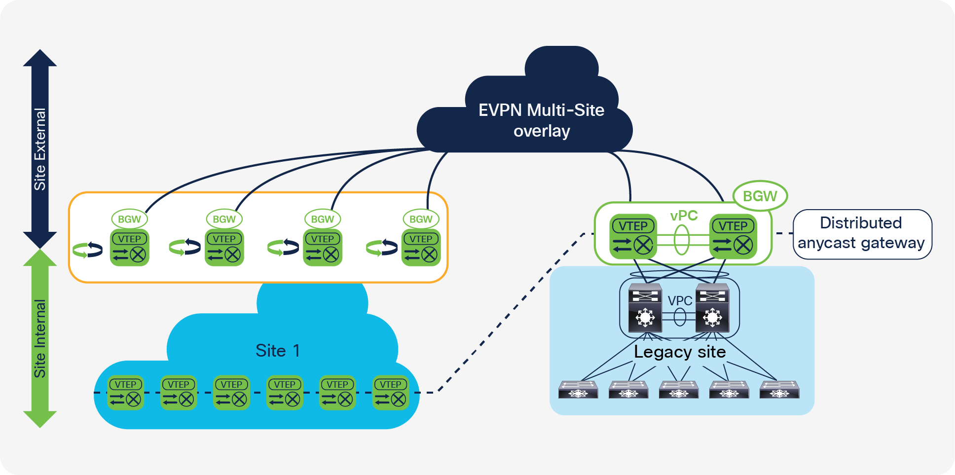
Legacy site integration
Additional considerations apply to first-hop gateway use and placement. VXLAN BGP EVPN uses the Distributed Anycast Gateway (DAG) as a first-hop gateway, whereas the legacy sites likely use a First-Hop Redundancy Protocol (FHRP) such as Hot Standby Router Protocol (HSRP), Virtual Router Redundancy Protocol (VRRP), or Gateway Load-Balancing Protocol (GLBP). The co-existence of these different first-hop gateway approaches is not supported today, and hence you need to achieve alignment between the legacy sites and VXLAN BGP EVPN sites. For legacy site integration, the BGW is allowed to operate in a vPC domain and to offer the first-hop gateway functions (in this case, DAG). This capability provides a first-hop gateway for the legacy site and helps ensure seamless endpoint mobility between legacy sites and VXLAN BGP EVPN sites.
Note: As of Cisco NX-OS 7.0(3)I7(1), the coexistence of different first-hop gateway modes (such as HSRP and DAG) is not supported for the same network. This restriction applies generally to VXLAN BGP EVPN deployments and is not specific to VXLAN EVPN Multi-Site architecture.
For more information on the use of vPC BGWs to integrate legacy networks with VXLAN EVPN fabrics, including a detailed description of the supported use cases and configuration exmaples, please refer to the “NextGen DCI with VXLAN EVPN Multi-Site Using vPC Border Gateways White Paper” available in the “For more information” section at the end of this document.
Network services integration is a big topic, especially when multiple sites are present and you need to distribute firewalls and load balancers across them. The EVPN Multi-Site BGW generally supports connection of network services (L4-L7 services) such as firewalls, load balancers, and Intrusion Detection System (IDS) and Intrusion Prevention System (IPS) applications. As of Cisco NX-OS 7.0(3)I7(1), all connectivity to the BGW must be implemented through a Layer 3 physical interface or subinterface. If the desired network services deployment can be achieved through routing and routing redundancy, EVPN Multi-Site architecture also supports these connectivity models. For cases in which Layer 2 redundancy, for instance, the use of vPC, is required, connectivity to the EVPN Multi-Site BGW is not currently supported. Also, connectivity models that use SVI and interface VLANs and IEEE 802.1q tagged Layer 2 interfaces (trunks) are not supported on the BGW.
To deploy network services in this cases, you can use a site-internal VTEP (that is, a services VTEP). Subsequent software releases will extend the capabilities to a BGW.
Network services deployment with EVPN Multi-Site architecture is covered in a separate document.
Verification and show commands
After you set up a VXLAN BGP EVPN Multi-Site environment, you need the tools necessary to verify the current state. This section explores the available show commands and their expected output. All output is based on the topology shown in Figure 25.
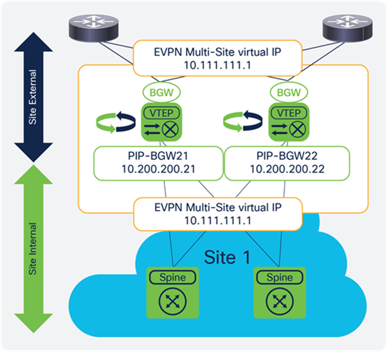
Show commands and verification
In addition to the show commands presented in this section, VXLAN OAM (NGOAM) works consistently for single-site and EVPN Multi-Site architecture. End-to-end VXLAN OAM is supported as of Cisco NX-OS 7.0(3)I7(1).
EVPN Multi-Site architecture provides additional status information about the BGW VTEP. The output now includes EVPN Multi-Site architecture configured and elapsed delay-restore time, the virtual router MAC address, and the virtual IP address and status.
BGW21-N93180EX# show nve interface nve 1 detail
Interface: nve1, State: Up, encapsulation: VXLAN
VPC Capability: VPC-VIP-Only [not-notified]
Local Router MAC: 00a3.8e9d.9267
Host Learning Mode: Control-Plane
Source-Interface: loopback1 (primary: 10.200.200.21, secondary: 0.0.0.0)
Source Interface State: Up
IR Capability Mode: No
Virtual RMAC Advertisement: No
NVE Flags:
Interface Handle: 0x49000001
Source Interface hold-down-time: 180
Source Interface hold-up-time: 30
Remaining hold-down time: 0 seconds
Multi-Site delay-restore time: 180 seconds
Multi-Site delay-restore time left: 0 seconds
Virtual Router MAC: 0200.0a6f.6f01
Interface state: nve-intf-add-complete
unknown-peer-forwarding: disable
down-stream vni config mode: n/a
Multisite bgw-if: loopback100 (ip: 10.111.111.1, admin: Up, oper: Up)
Multisite bgw-if oper down reason:
Nve Src node last notif sent: None
Nve Mcast Src node last notif sent: None
Nve MultiSite Src node last notif sent: Port-up
BGW21-N93180EX#
The EVPN Multi-Site delay-restore function can be triggered either by interface status tracking or by the launch of the BGW itself. The status of the EVPN Multi-Site virtual IP address indicates whether the relevant IP address is active for advertising through the underlay routing protocol.
If all site-external interfaces are down, the EVPN Multi-Site virtual IP address is moved to the operational Down state, and the reasons are shown.
BGW21-N93180EX# show nve multisite dci-links
Interface State
--------- -----
Ethernet1/1 Down
Ethernet1/2 Down
BGW21-N93180EX#
BGW21-N93180EX# show nve interface nve 1 detail
…
Multisite bgw-if: loopback100 (ip: 10.111.111.1, admin: Up, oper: Down)
Multisite bgw-if oper down reason: DCI isolated.
Similarly, if all site-internal interfaces are down, the EVPN Multi-Site virtual IP address is moved to the operational Down state, and the reasons are shown.
BGW21-N93180EX# show nve multisite fabric-links
Interface State
--------- -----
Ethernet1/53 Down
Ethernet1/54 Down
BGW21-N93180EX#
BGW21-N93180EX# show nve interface nve 1 detail
…
Multisite bgw-if: loopback100 (ip: 10.111.111.1, admin: Up, oper: Down)
Multisite bgw-if oper down reason: FABRIC isolated.
In addition to verification of the state, control-plane protocol actions are performed as described in the “Failure scenarios” section.
Site-internal and site-external interface status
With EVPN Multi-Site interface tracking, the BGW function and advertisement and participation are controlled. The output provided as part of the interface tracking allows verification of the state.
BGW21-N93180EX# show nve multisite dci-links
Interface State
--------- -----
Ethernet1/1 Down
Ethernet1/2 Up
BGW21-N93180EX# show nve multisite fabric-links
Interface State
--------- -----
Ethernet1/53 Up
Ethernet1/54 Up
BGW21-N93180EX#
Designated forwarder election status
The designated-forwarder election status can be viewed per BGW and per VLAN and L2VNI. The output shows the status of the overall configured local VLANs (active VLANs), the VLANs for which the local BGW is the designated forwarder (designated-forwarder VLANs), and the mapped Layer 2 VNIs (active VNIs). In addition, a list of all the BGWs viable for designated-forwarder election is shown (designated-forwarder list).
BGW21-N93180EX# show nve ethernet-segment
ESI: 0300.0000.0000.0100.0309
Parent interface: nve1
ES State: Up
Port-channel state: N/A
NVE Interface: nve1
NVE State: Up
Host Learning Mode: control-plane
Active Vlans: 1,10,2003
DF Vlans: 10
Active VNIs: 30010,50001
CC failed for VLANs:
VLAN CC timer: 0
Number of ES members: 2
My ordinal: 0
DF timer start time: 00:00:00
Config State: N/A
DF List: 10.200.200.21 10.200.200.22
ES route added to L2RIB: True
EAD/ES routes added to L2RIB: False
EAD/EVI route timer age: not running
----------------------------------------
Note: As of Cisco NX-OS 7.0(3)I7(1), the Layer 3 VNI is always shown as active on all BGWs because designated-forwarder election is not performed. The same status applies for the VLAN that is mapped to the L3VNI.
Designated-forwarder message exchange
In addition to the designated-forwarder election status, you can display the specific designated-forwarder election messages. For EVPN Multi-Site architecture, BGP EVPN Route Type 4 is used to perform designated-forwarder election. The output shows all the BGP EVPN route Type 4 instances that are learned on a given node with the relevant Ethernet Segment (ES) as the site ID and the origin’s BGW PIP address.
BGW21-N93180EX# show bgp l2vpn evpn route-type 4
BGP routing table information for VRF default, address family L2VPN EVPN
Route Distinguisher: 10.100.100.21:27001 (ES [0300.0000.0000.0100.0309 0])
BGP routing table entry for [4]:[0300.0000.0000.0100.0309]:[32]:[10.200.200.21]/136, version 59722
Paths: (1 available, best #1)
Flags: (0x000002) on xmit-list, is not in l2rib/evpn
Advertised path-id 1
Path type: local, path is valid, is best path
AS-Path: NONE, path locally originated
10.200.200.21 (metric 0) from 0.0.0.0 (10.100.100.21)
Origin IGP, MED not set, localpref 100, weight 32768
Extcommunity: ENCAP:8 RT:0000.0000.0001
Path-id 1 advertised to peers:
10.52.52.52 10.53.53.53 10.100.100.201 10.100.100.202
BGP routing table entry for [4]:[0300.0000.0000.0100.0309]:[32]:[10.200.200.22]/136, version 59736
Paths: (1 available, best #1)
Flags: (0x000012) on xmit-list, is in l2rib/evpn, is not in HW
Advertised path-id 1
Path type: internal, path is valid, is best path
Imported from 10.100.100.22:27001:[4]:[0300.0000.0000.0100.0309]:[32]:[10.200.200.22]/136
AS-Path: NONE, path sourced internal to AS
10.200.200.22 (metric 3) from 10.100.100.201 (10.100.100.201)
Origin IGP, MED not set, localpref 100, weight 0
Extcommunity: ENCAP:8 RT:0000.0000.0001
Originator: 10.100.100.22 Cluster list: 10.100.100.201
Path-id 1 not advertised to any peer
The important part of this output is not its detailed information, but the fact that one BGP EVPN route type 4 prefix must exist for each BGW at the local site. Thus, in the case of two BGWs, you need two prefixes in every BGW: one local to the BGW and one received remotely.
The preceding example shows a site with two BGWs. The BGW with PIP address 10.200.200.21 is local to the show output, and the BGW with PIP address 10.200.200.22 is local to the site and the prefix was received by the BGP EVPN.
Additional documentation about EVPN Multi-Site architecture and related topics can be found at the sites listed here.
Configuration guides and examples
Configuring VXLAN EVPN Multi-Site architecture (Cisco Nexus 9000 Series Switches): https://www.cisco.com/c/en/us/td/docs/switches/datacenter/nexus9000/sw/7-x/vxlan/configuration/guide/b_Cisco_Nexus_9000_Series_NX-OS_VXLAN_Configuration_Guide_7x/b_Cisco_Nexus_9000_Series_NX-OS_VXLAN_Configuration_Guide_7x_chapter_01100.html
Configuring VXLAN BGP EVPN (Cisco Nexus 9000 Series Switches): https://www.cisco.com/c/en/us/td/docs/switches/datacenter/nexus9000/sw/7-x/vxlan/configuration/guide/b_Cisco_Nexus_9000_Series_NX-OS_VXLAN_Configuration_Guide_7x/b_Cisco_Nexus_9000_Series_NX-OS_VXLAN_Configuration_Guide_7x_chapter_0100.html
VXLAN EVPN configuration example (Cisco Nexus 9000 Series Switches): https://communities.cisco.com/community/technology/datacenter/data-center-networking/blog/2015/05/19/vxlanevpn-configuration-example
Cisco programmable fabric with VXLAN BGP EVPN configuration guide: https://www.cisco.com/c/en/us/td/docs/switches/datacenter/pf/configuration/guide/b-pf-configuration.html
Building hierarchical fabrics with VXLAN EVPN Multi-Site architecture: https://www.cisco.com/c/dam/en/us/products/collateral/switches/nexus-9000-series-switches/at-a-glance-c45-739422.pdf
VXLAN innovations: VXLAN EVPN Multi-Site architecture (part 2 of 2): https://blogs.cisco.com/datacenter/vxlan-innovations-vxlan-evpn-multi-site-part-2-of-2
Design considerations and related references
The magic of superspines and RFC-7938 with overlays: https://learningnetwork.cisco.com/blogs/community_cafe/2017/10/17/the-magic-of-super-spines-and-rfc7938-with-overlays-guest-post
draft-sharma-multi-site-evpn - Multi-site EVPN based VXLAN using BGWs
https://tools.ietf.org/html/draft-sharma-multi-site-evpn
RFC-7432 (BGP MPLS-based Ethernet VPN): https://tools.ietf.org/html/rfc7432
draft-ietf-bess-evpn-overlay (network virtualization overlay solution using EVPN): https://tools.ietf.org/html/draft-ietf-bess-evpn-overlay
draft-ietf-bess-evpn-inter-subnet-forwarding (integrated routing and bridging in EVPN): https://tools.ietf.org/html/draft-ietf-bess-evpn-inter-subnet-forwarding
draft-ietf-bess-evpn-prefix-advertisement - IP Prefix Advertisement in EVPN
https://tools.ietf.org/html/draft-ietf-bess-evpn-prefix-advertisement
RFC-7947 (Internet exchange BGP route server): https://tools.ietf.org/html/rfc7947
BRKDCN-2035 (VXLAN BGP EVPN–based multipod, multifabric, and multisite architecture): https://www.ciscolive.com/online/connect/sessionDetail.ww?SESSION_ID=95611
BRKDCN-2125 (overlay management and visibility with VXLAN): https://www.ciscolive.com/online/connect/sessionDetail.ww?SESSION_ID=95613
Building data centers with VXLAN BGP EVPN (Cisco NX-OS perspective): https://www.ciscopress.com/store/building-data-centers-with-vxlan-bgp-evpn-a-cisco-nx-9781587144677
VXLAN BGP EVPN multifabric: https://www.cisco.com/c/en/us/products/collateral/switches/nexus-9000-series-switches/white-paper-c11-738358.html
VXLAN BGP EVPN and OTV interoperation (Cisco Nexus 7000 Series and 7700 platform switches): https://www.cisco.com/c/en/us/td/docs/switches/datacenter/nexus7000/sw/vxlan/config/cisco_nexus7000_vxlan_config_guide_8x/cisco_nexus7000_vxlan_config_guide_8x_chapter_01001.html