Configuring VXLAN BGP EVPN

This chapter contains the following sections:

Information About VXLAN BGP EVPN

Guidelines and Limitations for VXLAN BGP EVPN

VXLAN BGP EVPN has the following guidelines and limitations:

  • The following guidelines and limitations apply to VXLAN/VTEP:

    • SPAN source or destination is supported on any port.

    For more information, see the Cisco Nexus 9000 Series NX-OS System Management Configuration Guide, Release 7.x.

  • When SVI is enabled on a VTEP (flood and learn, or EVPN) regardless of ARP suppression, make sure that ARP-ETHER TCAM is carved using the hardware access-list tcam region arp-ether 256 double-wide command. This is not applicable to the Cisco Nexus 9200 and 9300-EX platform switches and Cisco Nexus 9500 platform switches with 9700-EX line cards.

  • Beginning with Cisco NX-OS Release 7.0(3)F3(3), VXLAN Layer 2 Gateway is supported only on the 9636C-RX line card. VXLAN and MPLS cannot be enabled on the Cisco Nexus 9508 switch at the same time.

  • Beginning with Cisco NX-OS Release 7.0(3)F3(3), if VXLAN is enabled, the Layer 2 Gateway cannot be enabled when there is any line card other than the 9636C-RX.

  • Beginning with Cisco NX-OS Release 7.0(3)I6(1), you can configure EVPN over segment routing or MPLS. See the Cisco Nexus 9000 Series NX-OS Label Switching Configuration Guide, Release 7.x for more information.

  • Beginning with Cisco NX-OS Release 7.0(3)I6(1), you can use MPLS tunnel encapsulation using the new CLI encapsulation mpls command. You can configure the label allocation mode for the EVPN address family. See the Cisco Nexus 9000 Series NX-OS Label Switching Configuration Guide, Release 7.x for more information.

  • In VXLAN EVPN setup that has 2K VNI scale configuration, the control plane down time takes more than 200 seconds. To avoid BGP flap, configure the graceful restart time to 300 seconds.

  • SVI and subinterfaces as uplinks are not supported.

  • In a VXLAN EVPN setup, border leaves must use unique route distinguishers, preferably using auto rd command. It is not supported to have same route distinguishers in different border leaves.

  • ARP suppression is only supported for a VNI if the VTEP hosts the First-Hop Gateway (Distributed Anycast Gateway) for this VNI. The VTEP and the SVI for this VLAN have to be properly configured for the distributed Anycast Gateway operation, for example, global Anycast Gateway MAC address configured and Anycast Gateway feature with the virtual IP address on the SVI.

  • The show commands with the internal keyword are not supported.

  • DHCP snooping (Dynamic Host Configuration Protocol snooping) is not supported on VXLAN VLANs.

  • RACLs are not supported on Layer 3 uplinks for VXLAN traffic. Egress VACLs support is not available for de-capsulated packets in the network to access direction on the inner payload.

    As a best practice, use PACLs/VACLs for the access to the network direction.

    See the Cisco Nexus 9000 Series NX-OS Security Configuration Guide for other guidelines and limitations for the VXLAN ACL feature.

  • QoS classification is not supported for VXLAN traffic in the network to access direction on the Layer 3 uplink interface.

    See the Cisco Nexus 9000 Series NX-OS Quality of Service Configuration Guide for other guidelines and limitations for the VXLAN QoS feature.

  • The QoS buffer-boost feature is not applicable for VXLAN traffic.

  • VTEP does not support Layer 3 subinterface uplinks that carry VXLAN encapsulated traffic.

  • Layer 3 interface uplinks that carry VXLAN encapsulated traffic do not support subinterfaces for non-VXLAN encapsulated traffic.

  • On Cisco Nexus 9000 PX/TX/PQ switches configured as VXLAN VTEPs, if any ALE 40G port is used as a VXLAN underlay port, configuring subinterfaces on either this or any other 40G port is not allowed and could lead to VXLAN traffic loss.

  • For Cisco NX-OS 7.0(3)I2(1) and later, a FEX HIF (FEX host interface port) is supported for a VLAN that is extended with VXLAN.

  • For eBGP, it is recommended to use a single overlay eBGP EVPN session between loopbacks.

  • EBGP peering from a VXLAN host to local VTEP is supported with loopback in tenant VRF as BGP update-source.

  • You must bind NVE to a loopback address that is separate from other loopback addresses that are required by Layer 3 protocols. NVE and other Layer 3 protocols using the same loopback is not supported.

  • VXLAN BGP EVPN does not support an NVE interface in a non-default VRF.

  • It is recommended to configure a single BGP session over the loopback for an overlay BGP session.

  • When configuring VXLAN BGP EVPN, only the "System Routing Mode: Default" is applicable for the following hardware platforms:

    • Cisco Nexus 9200, 9300-EX, and 9300-FX/FX2 platform switches

    • Cisco Nexus 9300 platform switches

    • Cisco Nexus 9500 platform switches with X9500 line cards

    • Cisco Nexus 9500 platform switches with -EX and -FX line cards

  • The “System Routing Mode: template-vxlan-scale” is not applicable to Cisco NX-OS Release 7.0(3)I5(2) and later.

  • When using VXLAN BGP EVPN with Cisco NX-OS Release 7.0(3)I4(x) or 7.0(3)I5(1), the “System Routing Mode: template-vxlan-scale” is required on the following hardware platforms:

    • Cisco Nexus 9300-EX platform switches

    • Cisco Nexus 9500 platform switches with -EX line cards

  • Changing the “System Routing Mode” requires a reload of the switch.

  • For Cisco NX-OS Release 7.0(3)I2(1) and later, VXLAN is supported on Cisco Nexus 9500 platform switches with the following line cards:

    • 9500-R

    • 9564PX

    • 9564TX

    • 9536PQ

    • 9700-EX

    • 9700-FX

  • When Cisco Nexus 9500 platform switches are used as VTEPs (7.0(3)I2(1) and later), 100G line cards are not supported on Cisco Nexus 9500 platform switches. This limitation does not apply to a Cisco Nexus 9500 platform switch with -EX or -FX line cards.

  • Cisco Nexus 9300 platform switches with 100G uplinks only support VXLAN switching/bridging. (7.0(3)I2(1) and later)

    Cisco Nexus 9200, 9300-EX, and 9300-FX platform switches do not have this restriction.


    Note


    For VXLAN routing support, a 40G uplink module is required.
  • The VXLAN UDP port number is used for VXLAN encapsulation. For Cisco Nexus NX-OS, the UDP port number is 4789. It complies with IETF standards and is not configurable.

  • For Cisco NX-OS Release 7.0(3)I1(2) and earlier, a static route with next-hop reachable over the VXLAN BGP EVPN route is not supported.

  • For Cisco Nexus 9200 platform switches that have the Application Spine Engine (ASE2), there exists a Layer 3 VXLAN (SVI) throughput issue. There is a data loss for packets of sizes 99–122. (7.0(3)I3(1) and later).

  • For the Cisco NX-OS 7.0(3)I2(3) release, the VXLAN network identifier (VNID) 16777215 is reserved and should not be configured explicitly.

  • For Cisco NX-OS Release 7.0(3)I4(1) and later, VXLAN supports In-Service Software Upgrade (ISSU).

  • VXLAN does not support co-existence with the GRE tunnel feature or the MPLS (static or segment-routing) feature on Cisco Nexus 9000 Series switches with a Network Forwarding Engine (NFE).

  • The vpc orphan-ports suspend command must be enabled for orphan ports that are connected to Cisco Nexus 9000 vPC VTEPs.

  • VTEP connected to FEX host interface ports is not supported (7.0(3)I2(1) and later).

  • In Cisco NX-OS Release 7.0(3)I4(1), resilient hashing (port-channel load-balancing resiliency) and VXLAN configurations are not compatible with VTEPs using ALE uplink ports.


    Note


    Resilient hashing is disabled by default.


  • For SVI-related triggers (such as shut/unshut or PIM enable/disable), a 30-second delay was added, allowing the Multicast FIB (MFIB) Distribution module (MFDM) to clear the hardware table before toggling between L2 and L3 modes or vice versa.


Note


For information about VXLAN BGP EVPN scalability, see the Verified Scalability Guide for your platform.


Considerations for VXLAN BGP EVPN Deployment

  • A loopback address is required when using the source-interface config command. The loopback address represents the local VTEP IP.

  • During boot-up of a switch (7.0(3)I2(2) and later), you can use the source-interface hold-down-time hold-down-time command to suppress advertisement of the NVE loopback address until the overlay has converged. The range for the hold-down-time is 0 - 1000 seconds. The default is 180 seconds.

  • To establish IP multicast routing in the core, IP multicast configuration, PIM configuration, and RP configuration is required.

  • VTEP to VTEP unicast reachability can be configured through any IGP/BGP protocol.

  • If the anycast gateway feature is enabled for a specific VNI, then the anyway gateway feature must be enabled on all VTEPs that have that VNI configured. Having the anycast gateway feature configured on only some of the VTEPs enabled for a specific VNI is not supported.

  • It is a requirement when changing the primary or secondary IP address of the NVE source interfaces to shut the NVE interface before changing the IP address.

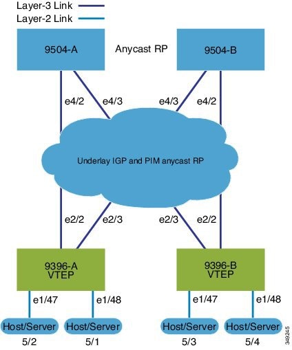
  • As a best practice, the RP for the multicast group should be configured only on the spine layer. Use the anycast RP for RP load balancing and redundancy.

  • Every tenant VRF needs a VRF overlay VLAN and SVI for VXLAN routing.

  • For scale environments, the VLAN IDs related to the VRF and Layer-3 VNI (L3VNI) must be reserved with the system vlan nve-overlay id command.

    This is required to optimize the VXLAN resource allocation to scale the following platforms:

    • Cisco Nexus 9200 platform switches beginning with Cisco NX-OS Release 7.0(3)I1(2) through 7.0(3)I5(2)

    • Cisco Nexus 9300-EX, 9300-FX, and 9300-FX2 platform switches beginning with Cisco NX-OS Release 7.0(3)I1(2) through 7.0(3)I5(2)

    • Cisco Nexus 9300 platform switches beginning with Cisco NX-OS Release 7.0(3)I1(2)


    Note


    Beginning with Cisco NX-OS Release 7.0(3)I5(2), the Cisco Nexus 9200, 9300-EX, and 9300-FX/FX2 platform switches do not require this command. Beginning with Cisco NX-OS Release 7.0(3)I5(2), it is strongly recommended to remove the command on Cisco Nexus 9200, 9300-EX, and 9300-FX/FX2 platform switches as it would disable Tenant Routed Multicast functionality on the VRF.


    The following example shows how to reserve the VLAN IDs related to the VRF and the Layer-3 VNI:

    system vlan nve-overlay id 2000
     
    vlan 2000
      vn-segment 50000
     
    interface Vlan2000
      vrf member MYVRF_50000
      ip forward
      ipv6 forward
    
    
    vrf context MYVRF_50000
      vni 50000

    Note


    The system vlan nve-overlay id command should be used for a VRF or a Layer-3 VNI (L3VNI) only. Do not use this command for regular VLANs or Layer-2 VNIs (L2VNI).


  • When configuring ARP suppression with BGP-EVPN, use the hardware access-list tcam region arp-ether size double-wide command to accommodate ARP in this region. (You must decrease the size of an existing TCAM region before using this command.)

vPC Considerations for VXLAN BGP EVPN Deployment

  • The loopback address used by NVE needs to be configured to have a primary IP address and a secondary IP address.

    The secondary IP address is used for all VxLAN traffic that includes multicast and unicast encapsulated traffic.

  • Each vPC peer needs to have separate BGP sessions to the spine.

  • vPC peers must have identical configurations.

    • Consistent VLAN to VN-segment mapping.

    • Consistent NVE1 binding to the same loopback interface

      • Using the same secondary IP address.

      • Using different primary IP addresses.

    • Consistent VNI to group mapping.

    • The VRF overlay VLAN should be a member of the peer-link port-channel.

  • For multicast, the vPC node that receives the (S, G) join from the RP (rendezvous point) becomes the DF (designated forwarder). On the DF node, encap routes are installed for multicast.

    Decap routes are installed based on the election of a decapper from between the vPC primary node and the vPC secondary node. The winner of the decap election is the node with the least cost to the RP. However, if the cost to the RP is the same for both nodes, the vPC primary node is elected.

    The winner of the decap election has the decap mroute installed. The other node does not have a decap route installed.

  • On a vPC device, BUM traffic (broadcast, unknown-unicast, and multicast traffic) from hosts is replicated on the peer-link. A copy is made of every native packet and each native packet is sent across the peer-link to service orphan-ports connected to the peer vPC switch.

    To prevent traffic loops in VXLAN networks, native packets ingressing the peer-link cannot be sent to an uplink. However, if the peer switch is the encapper, the copied packet traverses the peer-link and is sent to the uplink.


    Note


    Each copied packet is sent on a special internal VLAN (VLAN 4041).


  • When peer-link is shut, the loopback interface used by NVE on the vPC secondary is brought down and the status is Admin Shut. This is done so that the route to the loopback is withdrawn on the upstream and that the upstream can divert all traffic to the vPC primary.


    Note


    Orphans connected to the vPC secondary will experience loss of traffic for the period that the peer-link is shut. This is similar to Layer 2 orphans in a vPC secondary of a traditional vPC setup.


  • When the vPC domain is shut, the loopback interface used by NVE on the VTEP with shutdown vPC domain is brought down and the status is Admin Shut. This is done so that the route to the loopback is withdrawn on the upstream and that the upstream can divert all traffic to the other vPC VTEP.

  • When peer-link is no-shut, the NVE loopback address is brought up again and the route is advertised upstream, attracting traffic.

  • For vPC, the loopback interface has 2 IP addresses: the primary IP address and the secondary IP address.

    The primary IP address is unique and is used by Layer 3 protocols.

    The secondary IP address on loopback is necessary because the interface NVE uses it for the VTEP IP address. The secondary IP address must be same on both vPC peers.

  • The vPC peer-gateway feature must be enabled on both peers.

    As a best practice, use peer-switch, peer gateway, ip arp sync, ipv6 nd sync configurations for improved convergence in vPC topologies.

    In addition, increase the STP hello timer to 4 seconds to avoid unnecessary TCN generations when vPC role changes occur.

    The following is an example (best practice) of a vPC configuration:

    
    switch# sh ru vpc
    
    version 6.1(2)I3(1)
    feature vpc
    vpc domain 2
      peer-switch
      peer-keepalive destination 172.29.206.65 source 172.29.206.64
      peer-gateway
      ipv6 nd synchronize
      ip arp synchronize
    
    
  • On a vPC pair, shutting down NVE or NVE loopback on one of the vPC nodes is not a supported configuration. This means that traffic failover on one-side NVE shut or one-side loopback shut is not supported.

  • Redundant anycast RPs configured in the network for multicast load-balancing and RP redundancy are supported on vPC VTEP topologies.

  • Enabling vpc peer-gateway configuration is mandatory. For peer-gateway functionality, at least one backup routing SVI is required to be enabled across peer-link and also configured with PIM. This provides a backup routing path in the case when VTEP loses complete connectivity to the spine. Remote peer reachability is re-routed over the peer-link in this case.

    The following is an example of SVI with PIM enabled:

    
    swithch# sh ru int vlan 2
    
    interface Vlan2
      description special_svi_over_peer-link
      no shutdown
      ip address 30.2.1.1/30
      ip pim sparse-mode


    Note


    The SVI must be configured on both vPC peers and requires PIM to be enabled.


  • As a best practice when changing the secondary IP address of an anycast vPC VTEP, the NVE interfaces on both the vPC primary and the vPC secondary should be shut before the IP changes are made.

  • To provide redundancy and failover of VXLAN traffic when a VTEP loses all of its uplinks to the spine, it is recommended to run a Layer 3 link or an SVI link over the peer-link between vPC peers.

  • If DHCP Relay is required in VRF for DHCP clients or if loopback in VRF is required for reachability test on a vPC pair, it is necessary to create a backup SVI per VRF with PIM enabled.

    
    swithch# sh ru int vlan 20
    
    interface Vlan20
    description backup routing svi for VRF Green
    vrf member GREEN
    no shutdown
    ip address 30.2.10.1/30
    

Network Considerations for VXLAN Deployments

  • MTU Size in the Transport Network

    Due to the MAC-to-UDP encapsulation, VXLAN introduces 50-byte overhead to the original frames. Therefore, the maximum transmission unit (MTU) in the transport network must be increased by 50 bytes. If the overlays use a 1500-byte MTU, the transport network must be configured to accommodate 1550-byte packets at a minimum. Jumbo-frame support in the transport network is required if the overlay applications tend to use larger frame sizes than 1500 bytes.

  • ECMP and LACP Hashing Algorithms in the Transport Network

    As described in a previous section, Cisco Nexus 9000 Series Switches introduce a level of entropy in the source UDP port for ECMP and LACP hashing in the transport network. As a way to augment this implementation, the transport network uses an ECMP or LACP hashing algorithm that takes the UDP source port as input for hashing, which achieves the best load-sharing results for VXLAN encapsulated traffic.

  • Multicast Group Scaling

    The VXLAN implementation on Cisco Nexus 9000 Series Switches uses multicast tunnels for broadcast, unknown unicast, and multicast traffic forwarding. Ideally, one VXLAN segment mapping to one IP multicast group is the way to provide the optimal multicast forwarding. It is possible, however, to have multiple VXLAN segments share a single IP multicast group in the core network. VXLAN can support up to 16 million logical Layer 2 segments, using the 24-bit VNID field in the header. With one-to-one mapping between VXLAN segments and IP multicast groups, an increase in the number of VXLAN segments causes a parallel increase in the required multicast address space and the number of forwarding states on the core network devices. At some point, multicast scalability in the transport network can become a concern. In this case, mapping multiple VXLAN segments to a single multicast group can help conserve multicast control plane resources on the core devices and achieve the desired VXLAN scalability. However, this mapping comes at the cost of suboptimal multicast forwarding. Packets forwarded to the multicast group for one tenant are now sent to the VTEPs of other tenants that are sharing the same multicast group. This causes inefficient utilization of multicast data plane resources. Therefore, this solution is a trade-off between control plane scalability and data plane efficiency.

    Despite the suboptimal multicast replication and forwarding, having multitenant VXLAN networks to share a multicast group does not bring any implications to the Layer 2 isolation between the tenant networks. After receiving an encapsulated packet from the multicast group, a VTEP checks and validates the VNID in the VXLAN header of the packet. The VTEP discards the packet if the VNID is unknown to it. Only when the VNID matches one of the VTEP’s local VXLAN VNIDs, does it forward the packet to that VXLAN segment. Other tenant networks will not receive the packet. Thus, the segregation between VXLAN segments is not compromised.

Considerations for the Transport Network

The following are considerations for the configuration of the transport network:

  • On the VTEP device:

    • Enable and configure IP multicast.*

    • Create and configure a loopback interface with a /32 IP address.

      (For vPC VTEPs, you must configure primary and secondary /32 IP addresses.)

    • Enable UP multicast on the loopback interface. *

    • Advertise the loopback interface /32 addresses throught the routing protocol (static route) that runs in the transport network.

    • Enable IP multicast on the uplink outgoing physical interface. *

  • Throughout the transport network:

    • Enable and configure IP multicast.*


Note


* Not required for static ingress replication or BGP EVPN ingress replication.


Considerations for Tunneling VXLAN

DC Fabrics with VXLAN BGP EVPN are becoming the transport infrastructure for overlays. These overlays, often originated on the server (Host Overlay), require integration or transport over the top of the existing transport infrastructure (Network Overlay).

Nested VXLAN (Host Overlay over Network Overlay) support has been added starting with Cisco NX-OS Release 7.0(3)I7(4) and Cisco NX-OS Release 9.2(2) on the Cisco Nexus 9200, 9300-EX, 9300-FX, and 9300-FX2 platform switches.

Figure 1. Host Overlay

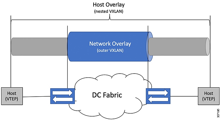
To provide Nested VXLAN support, the switch hardware and software must differentiate between two different VXLAN profiles:

  • VXLAN originated behind the Hardware VTEP for transport over VXLAN BGP EVPN (nested VXLAN)

  • VXLAN originated behind the Hardware VTEP to integrated with VXLAN BGP EVPN (BUD Node)

The detection of the two different VXLAN profiles is automatic and no specific configuration is needed for nested VXLAN. As soon as VXLAN encapsulated traffic arrives in a VXLAN enabled VLAN, the traffic is transported over the VXLAN BGP EVPN enabled DC Fabric.

The following attachment modes are supported for Nested VXLAN:

  • Untagged traffic (in native VLAN on a trunk port or on an access port)

  • Tagged traffic (tagged VLAN on a IEEE 802.1Q trunk port)

  • Untagged and tagged traffic that is attached to a vPC domain

  • Untagged traffic on a Layer 3 interface of a Layer 3 port-channel interface

BGP EVPN Considerations for VXLAN Deployment

Commands for BGP EVPN

The following describes commands to support BGP EVPN VXLAN control planes.

Command

Description

member vni range [associate-vrf]

Associate VXLAN VNIs (Virtual Network Identifiers) with the NVE interface

The attribute associate- vrf is used to identify and separate processing VNIs that are associated with a VRF and used for routing.

Note


The VRF and VNI specified with this command must match the configuration of the VNI under the VRF.

show nve vni

show nve vni summary

Displays information that determine if the VNI is configured for peer and host learning via the control plane or data plane.

show bgp l2vpn evpn

show bgp l2vpn evpn summary

Displays the Layer 2 VPN EVPN address family.

host-reachability protocol bgp

Specifies BGP as the mechanism for host reachability advertisement.

suppress-arp

Suppresses ARP under Layer 2 VNI.

fabric forwarding anycast-gateway-mac

Configures anycast gateway MAC of the switch.

vrf context

Creates the VRF and enter the VRF mode.

nv overlay evpn

Enables/Disables the Ethernet VPN (EVPN).

router bgp

Configures the Border Gateway Protocol (BGP).

system vlan nve-overlay id range

For scale environments, the VLAN IDs related to the VRF and Layer-3 VNI (L3VNI) must be reserved with the system vlan nve-overlay id command.

This is required to optimize the VXLAN resource allocation to scale the following platforms:

  • Cisco Nexus 9200 platform switches beginning with the Cisco NX-OS Release 7.0(3)I1(2) through 7.0(3)I5(2)

  • Cisco Nexus 9300-EX, 9300-FX, and 9300-FX2 platforms switches beginning with the Cisco NX-OS Release 7.0(3)I1(2) through 7.0(3)I5(2)

  • Cisco Nexus 9300 platforms switches beginning with the Cisco NX-OS Release 7.0(3)I1(2)

  • Cisco Nexus 9500 platforms switches with -EX and -FX line cards.

Note


Beginning with the Cisco NX-OS Release 7.0(3)I5(2), the Cisco Nexus 9200, Cisco Nexus 9300-EX, 9300-FX, and 9300-FX2 do not require this command. Beginning with Cisco NX-OS Release 7.0(3)I5(2), it is strongly recommended to remove the command on Cisco Nexus 9200, 9300-EX, 9300-FX, and 9300-FX2 platform switches as it would disable Tenant Routed Multicast functionality on the VRF.

Note


The system vlan nve-overlay id command should be used for a VRF or a Layer-3 VNI (L3VNI) only. Do not use this command for regular VLANs or Layer-2 VNIs (L2VNI).

suppress mac-route

Suppresses the BGP MAC route so that BGP only sends the MAC/IP route for a host.

Under NVE, the MAC updates for all VNIs are suppressed.

Note

 
  • Receive-side — Suppressing the MAC route depends upon the capability of the remote EVPN peer to derive a MAC route from the MAC/IP route (7.0(3)I2(2) and later). Avoid using the “suppress mac-route” command if devices in the network are running an earlier NX-OS release.

  • Send-side — Suppressing the MAC route means that the sender has a MAC/IP route. If your configuration has pure-Layer 2 VNIs (such as no corresponding VRF or Layer3-VNI), then there is no corresponding MAC/IP and you should avoid using the “suppress mac-route” command.

Configuring VXLAN BGP EVPN

Enabling VXLAN

Enable VXLAN and the EVPN.

Procedure

  Command or Action Purpose

Step 1

feature vn-segment

Enable VLAN-based VXLAN

Step 2

feature nv overlay

Enable VXLAN

Step 3

nv overlay evpn

Enable the EVPN control plane for VXLAN.

Configuring VLAN and VXLAN VNI

Procedure

  Command or Action Purpose

Step 1

vlan number

Specify VLAN.

Step 2

vn-segment number

Map VLAN to VXLAN VNI to configure Layer 2 VNI under VXLAN VLAN.

Configuring VRF for VXLAN Routing

Configure the tenant VRF.

Procedure

  Command or Action Purpose

Step 1

vrf context vxlan

Configure the VRF.

Step 2

vni number

Specify VNI.

Step 3

rd auto

Specify VRF RD (route distinguisher).

Step 4

address-family ipv4 unicast

Configure address family for IPv4.

Step 5

route-target both auto

Note


Specifying the auto option is applicable only for IBGP.

Manually configured route targets are required for EBGP.

Step 6

route-target both auto evpn

Note


Specifying the auto option is applicable only for IBGP. The auto option is available beginning with Cisco NX-OS Release 7.0(3)I7(1).

Manually configured route targets are required for EBGP.

Step 7

address-family ipv6 unicast

Configure address family for IPv6.

Step 8

route-target both auto

Note


Specifying the auto option is applicable only for IBGP. The auto option is available beginning with Cisco NX-OS Release 7.0(3)I7(1).

Manually configured route targets are required for EBGP.

Step 9

route-target both auto evpn

Note


Specifying the auto option is applicable only for IBGP.

Manually configured route targets are required for EBGP.

About RD Auto

The auto-derived Route Distinguisher (rd auto) is based on the Type 1 encoding format as described in IETF RFC 4364 section 4.2 https://tools.ietf.org/html/rfc4364#section-4.2. The Type 1 encoding allows a 4-byte administrative field and a 2-byte numbering field. Within Cisco NX-OS, the auto derived RD is constructed with the IP address of the BGP Router ID as the 4-byte administrative field (RID) and the internal VRF identifier for the 2-byte numbering field (VRF ID).

The 2-byte numbering field is always derived from the VRF, but results in a different numbering scheme depending on its use for the IP-VRF or the MAC-VRF:

  • The 2-byte numbering field for the IP-VRF uses the internal VRF ID starting at 1 and increments. VRF IDs 1 and 2 are reserved for the default VRF and the management VRF respectively. The first custom defined IP VRF uses VRF ID 3.

  • The 2-byte numbering field for the MAC-VRF uses the VLAN ID + 32767, which results in 32768 for VLAN ID 1 and incrementing.

Example auto-derived Route Distinguisher (RD)

  • IP-VRF with BGP Router ID 192.0.2.1 and VRF ID 6 - RD 192.0.2.1:6

  • MAC-VRF with BGP Router ID 192.0.2.1 and VLAN 20 - RD 192.0.2.1:32787

About Route-Target Auto

The auto-derived Route-Target (route-target import/export/both auto) is based on the Type 0 encoding format as described in IETF RFC 4364 section 4.2 (https://tools.ietf.org/html/rfc4364#section-4.2). IETF RFC 4364 section 4.2 describes the Route Distinguisher format and IETF RFC 4364 section 4.3.1 refers that it is desirable to use a similar format for the Route-Targets. The Type 0 encoding allows a 2-byte administrative field and a 4-byte numbering field. Within Cisco NX-OS, the auto derived Route-Target is constructed with the Autonomous System Number (ASN) as the 2-byte administrative field and the Service Identifier (VNI) for the 4-byte numbering field.

Examples of an auto derived Route-Target (RT):

  • IP-VRF within ASN 65001 and L3VNI 50001 - Route-Target 65001:50001

  • MAC-VRF within ASN 65001 and L2VNI 30001 - Route-Target 65001:30001

For Multi-AS environments, the Route-Targets must either be statically defined or rewritten to match the ASN portion of the Route-Targets.

https://www.cisco.com/c/en/us/td/docs/switches/datacenter/nexus9000/sw/7-x/command_references/configuration_commands/b_N9K_Config_Commands_703i7x/b_N9K_Config_Commands_703i7x_chapter_010010.html#wp4498893710

Note


Auto derived Route-Targets for a 4-byte ASN are not supported.


Configuring SVI for Hosts for VXLAN Routing

Configure the SVI for hosts.

Procedure

  Command or Action Purpose

Step 1

vlan number

Specify VLAN

Step 2

interface vlan-number

Specify VLAN interface.

Step 3

vrf member vxlan-number

Configure SVI for host.

Step 4

ip address address

Specify IP address.

Configuring VRF Overlay VLAN for VXLAN Routing

Procedure

  Command or Action Purpose

Step 1

vlan number

Specify VLAN.

Step 2

vn-segment number

Specify vn-segment.

Configuring VNI Under VRF for VXLAN Routing

Configures a Layer 3 VNI under a VRF overlay VLAN. (A VRF overlay VLAN is a VLAN that is not associated with any server facing ports. All VXLAN VNIs that are mapped to a VRF, need to have their own internal VLANs allocated to it.)

Procedure

  Command or Action Purpose

Step 1

vrf context vxlan

Create a VXLAN Tenant VRF

Step 2

vni number

Configure Layer 3 VNI under VRF.

Configuring Anycast Gateway for VXLAN Routing

Procedure

  Command or Action Purpose

Step 1

fabric forwarding anycast-gateway-mac address

Configure distributed gateway virtual MAC address.

Note


One virtual MAC per VTEP

Note


All VTEPs must have the same virtual MAC address.

Step 2

fabric forwarding mode anycast-gateway

Associate SVI with Anycast Gateway under VLAN configuration mode.

Configuring the NVE Interface and VNIs

Procedure

  Command or Action Purpose

Step 1

interface nve-interface

Configure the NVE interface.

Step 2

host-reachability protocol bgp

This defines BGP as the mechanism for host reachability advertisement

Step 3

member vni vni associate-vrf

Add Layer-3 VNIs, one per tenant VRF, to the overlay.

Note


Required for VXLAN routing only.

Step 4

member vni vni

Add Layer 2 VNIs to the tunnel interface.

Step 5

mcast-group address

Configure the mcast group on a per-VNI basis

Configuring BGP on the VTEP

Procedure

  Command or Action Purpose

Step 1

router bgp number

Configure BGP.

Step 2

router-id address

Specify router address.

Step 3

neighbor address remote-as number

Define MP-BGP neighbors. Under each neighbor define l2vpn evpn.

Step 4

address-family ipv4 unicast

Configure address family for IPv4.

Step 5

address-family l2vpn evpn

Configure address family Layer 2 VPN EVPN under the BGP neighbor.

Note


Address-family ipv4 evpn for vxlan host-based routing

Step 6

(Optional) Allowas-in

(Optional)

Allows duplicate AS numbers in the AS path. Configure this parameter on the leaf for eBGP when all leafs are using the same AS, but the spines have a different AS than leafs.

Step 7

send-community extended

Configures community for BGP neighbors.

Step 8

vrf vrf-name

Specify VRF.

Step 9

address-family ipv4 unicast

Configure address family for IPv4.

Step 10

advertise l2vpn evpn

Enable advertising EVPN routes.

Step 11

address-family ipv6 unicast

Configure address family for IPv6.

Step 12

advertise l2vpn evpn

Enable advertising EVPN routes.

Note


To disable advertisement for a VRF toward the EVPN, disable the VNI in NVE by entering the no member vni vni associate-vrf command in interface nve1. The vni is the VNI associated with that particular VRF.

Configuring RD and Route Targets for VXLAN Bridging

Procedure

  Command or Action Purpose

Step 1

evpn

Configure VRF.

Step 2

vni number l2

Note


Only Layer 2 VNIs need to be specified.

Step 3

rd auto

Define VRF RD (route distinguisher) to configure VRF context.

Step 4

route-target import auto

Define VRF Route Target and import policies.

Step 5

route-target export auto

Define VRF Route Target and export policies.

About RD Auto

The auto-derived Route Distinguisher (rd auto) is based on the Type 1 encoding format as described in IETF RFC 4364 section 4.2 https://tools.ietf.org/html/rfc4364#section-4.2. The Type 1 encoding allows a 4-byte administrative field and a 2-byte numbering field. Within Cisco NX-OS, the auto derived RD is constructed with the IP address of the BGP Router ID as the 4-byte administrative field (RID) and the internal VRF identifier for the 2-byte numbering field (VRF ID).

The 2-byte numbering field is always derived from the VRF, but results in a different numbering scheme depending on its use for the IP-VRF or the MAC-VRF:

  • The 2-byte numbering field for the IP-VRF uses the internal VRF ID starting at 1 and increments. VRF IDs 1 and 2 are reserved for the default VRF and the management VRF respectively. The first custom defined IP VRF uses VRF ID 3.

  • The 2-byte numbering field for the MAC-VRF uses the VLAN ID + 32767, which results in 32768 for VLAN ID 1 and incrementing.

Example auto-derived Route Distinguisher (RD)

  • IP-VRF with BGP Router ID 192.0.2.1 and VRF ID 6 - RD 192.0.2.1:6

  • MAC-VRF with BGP Router ID 192.0.2.1 and VLAN 20 - RD 192.0.2.1:32787

About Route-Target Auto

The auto-derived Route-Target (route-target import/export/both auto) is based on the Type 0 encoding format as described in IETF RFC 4364 section 4.2 (https://tools.ietf.org/html/rfc4364#section-4.2). IETF RFC 4364 section 4.2 describes the Route Distinguisher format and IETF RFC 4364 section 4.3.1 refers that it is desirable to use a similar format for the Route-Targets. The Type 0 encoding allows a 2-byte administrative field and a 4-byte numbering field. Within Cisco NX-OS, the auto derived Route-Target is constructed with the Autonomous System Number (ASN) as the 2-byte administrative field and the Service Identifier (VNI) for the 4-byte numbering field.

Examples of an auto derived Route-Target (RT):

  • IP-VRF within ASN 65001 and L3VNI 50001 - Route-Target 65001:50001

  • MAC-VRF within ASN 65001 and L2VNI 30001 - Route-Target 65001:30001

For Multi-AS environments, the Route-Targets must either be statically defined or rewritten to match the ASN portion of the Route-Targets.

https://www.cisco.com/c/en/us/td/docs/switches/datacenter/nexus9000/sw/7-x/command_references/configuration_commands/b_N9K_Config_Commands_703i7x/b_N9K_Config_Commands_703i7x_chapter_010010.html#wp4498893710

Note


Auto derived Route-Targets for a 4-byte ASN are not supported.


Configuring VXLAN EVPN Ingress Replication

For VXLAN EVPN ingress replication, the VXLAN VTEP uses a list of IP addresses of other VTEPS in the network to send BUM (broadcast, unknown unicast and multicast) traffic. These IP addresses are exchanged between VTEPs through the BGP EVPN control plane.


Note


VXLAN EVPN ingress replication is supported on:

  • Cisco Nexus Series 9300 Series switches (7.0(3)I1(2) and later).

  • Cisco Nexus Series 9500 Series switches (7.0(3)I2(1) and later).


Before you begin

The following are required before configuring VXLAN EVPN ingress replication (7.0(3)I1(2) and later):

  • Enable VXLAN

  • Configure VLAN and VXLAN VNI

  • Configure BGP on the VTEP

  • Configure RD and Route Targets for VXLAN Bridging

Procedure

  Command or Action Purpose

Step 1

interface nve-interface

Configure the NVE interface.

Step 2

host-reachability protocol bgp

This defines BGP as the mechanism for host reachability advertisement

Step 3

member vni vni associate-vrf

Add Layer-3 VNIs, one per tenant VRF, to the overlay.

Note


Required for VXLAN routing only.

Step 4

member vni vni

Add Layer 2 VNIs to the tunnel interface.

Step 5

ingress-replication protocol bgp

Enables the VTEP to exchange local and remote VTEP IP addresses on the VNI in order to create the ingress replication list. This enables sending and receiving BUM traffic for the VNI.

Note


Using ingress-replication protocol bgp avoids the need for any multicast configurations that might have been required for configuring the underlay.

Configuring BGP for EVPN on the Spine

Procedure

  Command or Action Purpose

Step 1

route-map permitall permit 10

Configure route-map.

Note


The route-map keeps the next-hop unchanged for EVPN routes.

  • Required for eBGP.

  • Optional for iBGP.

Step 2

set ip next-hop unchanged

Set next-hop address.

Note


The route-map keeps the next-hop unchanged for EVPN routes.

  • Required for eBGP.

  • Optional for iBGP.

Note


When two next hops are enabled, next hop ordering is not maintained.

If one of the next hops is a VXLAN next hop and the other next hop is local reachable via FIB/AM/Hmm, the local next hop reachable via FIB/AM/Hmm is always taken irrespective of the order. Directly/locally connected next hops are always given priority over remotely connected next hops.

Step 3

router bgp autonomous system number

Specify BGP.

Step 4

address-family l2vpn evpn

Configure address family Layer 2 VPN EVPN under the BGP neighbor.

Step 5

retain route-target all

Configure retain route-target all under address-family Layer 2 VPN EVPN [global].

Note


Required for eBGP. Allows the spine to retain and advertise all EVPN routes when there are no local VNI configured with matching import route targets.

Step 6

neighbor address remote-as number

Define neighbor.

Step 7

address-family l2vpn evpn

Configure address family Layer 2 VPN EVPN under the BGP neighbor.

Step 8

disable-peer-as-check

Disables checking the peer AS number during route advertisement. Configure this parameter on the spine for eBGP when all leafs are using the same AS but the spines have a different AS than leafs.

Note


Required for eBGP.

Step 9

send-community extended

Configures community for BGP neighbors.

Step 10

route-map permitall out

Applies route-map to keep the next-hop unchanged.

Note


Required for eBGP.

Suppressing ARP

Suppressing ARP includes changing the size of the ACL ternary content addressable memory (TCAM) regions in the hardware.


Note


For information on configuring ACL TCAM regions, see the Configuring IP ACLs chapter of the Cisco Nexus 9000 Series NX-OS Security Configuration Guide.


Procedure

  Command or Action Purpose

Step 1

hardware access-list tcam region arp-ether size double-wide

Configure TCAM region to suppress ARP.

tcam-size —TCAM size. The size has to be a multiple of 256. If the size is more than 256, it has to be a multiple of 512.

Note


Reload is required for the TCAM configuration to be in effect.

Note


Configuring the hardware access-list tcam region arp-ether size double-wide is not required on Cisco Nexus 9200 Series switches.

Step 2

interface nve 1

Create the network virtualization endpoint (NVE) interface.

Step 3

member vni vni-id

Specify VNI ID.

Step 4

suppress-arp

Configure to suppress ARP under Layer 2 VNI.

Step 5

copy running-config start-up-config

Saves the change persistently through reboots and restarts by copying the running configuration to the startup configuration.

Disabling VXLANs

Procedure

  Command or Action Purpose

Step 1

configure terminal

Enters configuration mode.

Step 2

no nv overlay evpn

Disables EVPN control plane.

Step 3

no feature vn-segment-vlan-based

Disables the global mode for all VXLAN bridge domains

Step 4

no feature nv overlay

Disables the VXLAN feature.

Step 5

(Optional) copy running-config startup-config

(Optional)

Saves the change persistently through reboots and restarts by copying the running configuration to the startup configuration.

Duplicate Detection for IP and MAC Addresses

Cisco NX-OS supports duplicate detection for IP and MAC addresses. This enables the detection of duplicate IP or MAC addresses based on the number of moves in a given time-interval (seconds).

The default is 5 moves in 180 seconds. (Default number of moves is 5 moves. Default time-interval is 180 seconds.)

  • For IP addresses:

    • After the 5th move within 180 seconds, the switch starts a 30 second lock (hold down timer) before checking to see if the duplication still exists (an effort to prevent an increment of the sequence bit). This 30 second lock can occur 5 times within 24 hours (this means 5 moves in 180 seconds for 5 times) before the switch permanently locks or freezes the duplicate entry. (show fabric forwarding ip local-host-db vrf abc )

  • For MAC addresses:

    • After the 5th move within 180 seconds, the switch starts a 30 second lock (hold down timer) before checking to see if the duplication still exists (an effort to prevent an increment of the sequence bit). This 30 second lock can occur 3 times within 24 hours (this means 5 moves in 180 seconds for 3 times) before the switch permanently locks or freezes the duplicate entry. (show l2rib internal permanently-frozen-list )

  • Wherever a MAC address is permanently frozen, a syslog message with written by L2RIB.

    
    2017 Jul  5 10:27:34 leaf %$ VDC-1 %$  %USER-2-SYSTEM_MSG: Unfreeze limit (3) hit, MAC 0000.0033.3333in topo: 200 is permanently frozen - l2rib
    2017 Jul  5 10:27:34 leaf %$ VDC-1 %$  %USER-2-SYSTEM_MSG: Detected duplicate host 0000.0033.3333, topology 200, during Local update, with host located at remote VTEP 1.2.3.4, VNI 2 - l2rib 
    2017 Jul  5 10:27:34 leaf %$ VDC-1 %$  %USER-2-SYSTEM_MSG: Unfreeze limit (3) hit, MAC 0000.0033.3334in topo: 200 is permanently frozen - l2rib        
    2017 Jul  5 10:27:34 leaf %$ VDC-1 %$  %USER-2-SYSTEM_MSG: Detected duplicate host 0000.0033.3334, topology 200, during Local update, with host l


The following are example commands to help the configuration of the number of VM moves in a specific time interval (seconds) for duplicate IP-detection:

Command

Description


switch(config)# fabric forwarding ?
      anycast-gateway-mac 
      dup-host-ip-addr-detection 

Available sub-commands:

  • Anycast gateway MAC of the switch.

  • To detect duplicate host addresses in n seconds.


switch(config)# fabric forwarding dup-host-ip-addr-detection ?
      <1-1000>  

The number of host moves allowed in n seconds. The range is 1 to 1000 moves; default is 5 moves.

    
switch(config)# fabric forwarding dup-host-ip-addr-detection 100 ?
      <2-36000>  

The duplicate detection timeout in seconds for the number of host moves. The range is 2 to 36000 seconds; default is 180 seconds.

    
switch(config)# fabric forwarding dup-host-ip-addr-detection 100 10

Detects duplicate host addresses (limited to 100 moves) in a period of 10 seconds.

The following are example commands to help the configuration of the number of VM moves in a specific time interval (seconds) for duplicate MAC-detection:

Command

Description


 switch(config)# l2rib dup-host-mac-detection ?
      <1-1000>  
      default   

Available sub-commands for L2RIB:

  • The number of host moves allowed in n seconds. The range is 1 to 1000 moves.

  • Default setting (5 moves in 180 in seconds).


 switch(config)# l2rib dup-host-mac-detection 100 ?
      <2-36000>  
 

The duplicate detection timeout in seconds for the number of host moves. The range is 2 to 36000 seconds; default is 180 seconds.

    
switch(config)# l2rib dup-host-mac-detection 100 10

Detects duplicate host addresses (limited to 100 moves) in a period of 10 seconds.

Enabling Nuage Controller Interoperability

The following steps enable Nuage controller interoperability.

Procedure

  Command or Action Purpose

Step 1

nuage controller interop

Global command to enable interoperability mode.

Step 2

router bgp number

Configure BGP.

Step 3

address-family l2vpn evpn

Configure address family Layer 2 VPN EVPN under the BGP neighbor.

Step 4

advertise-system-mac

Enable Nuage interoperability mode for BGP.

Step 5

allow-vni-in-ethertag

Enable Nuage interoperability mode for BGP.

Step 6

route-map permitall permit 10

Configure route-map to permit all.

Step 7

router bgp number

Configure BGP.

Step 8

vrf vrf-name

Specify tenant VRF.

Step 9

address-family ipv4 unicast

Configure address family for IPv4.

Step 10

advertise l2vpn evpn

Enable advertising EVPN routes.

Step 11

redistribute hmm route-map permitall

Enables advertise host tenant routes as evpn type-5 routes for interoperability.

Example

The following is an example to enable Nuage controller interoperability:


/*** Enable interoperability mode at global level. ***/
switch(config)# nuage controller interop 

/*** Configure BGP to enable interoperability mode. ***/
switch(config)# router bgp 1001
switch(config-router)# address-family l2vpn evpn
switch(config-router-af)# advertise-system-mac
switch(config-router-af)# allow-vni-in-ethertag

/*** Advertise host tenant routes as evpn type-5 routes for interoperability. ***/
switch(config)# route-map permitall permit 10 
switch(config)# router bgp 1001
switch(config-router)# vrf vni-491830
switch(config-router-vrf)# address-family ipv4 unicast
switch(config-router-vrf-af)# advertise l2vpn evpn
switch(config-router-vrf-af)# redistribute hmm route-map permitall

Verifying the VXLAN BGP EVPN Configuration

To display the VXLAN BGP EVPN configuration information, enter one of the following commands:

Command

Purpose

show nve vrf

Displays VRFs and associated VNIs

show bgp l2vpn evpn

Displays routing table information.

show ip arp suppression-cache [detail | summary | vlan vlan | statistics ]

Displays ARP suppression information.

show vxlan interface

Displays VXLAN interface status.

show vxlan interface | count

Displays VXLAN VLAN logical port VP count.

Note


A VP is allocated on a per-port per-VLAN basis. The sum of all VPs across all VXLAN-enabled Layer 2 ports gives the total logical port VP count. For example, if there are 10 Layer 2 trunk interfaces, each with 10 VXLAN VLANs, then the total VXLAN VLAN logical port VP count is 10*10 = 100.

show l2route evpn mac [all | evi evi [bgp | local | static | vxlan | arp]]

Displays Layer 2 route information.

show l2route evpn fl all

Displays all fl routes.

show l2route evpn imet all

Displays all imet routes.

show l2route evpn mac-ip all

show l2route evpn mac-ip all detail

Displays all MAC IP routes.

show l2route topology

Displays Layer 2 route topology.


Note


Although the show ip bgp command is available for verifying a BGP configuration, as a best practice, it is preferable to use the show bgp command instead.


Example of VXLAN BGP EVPN (EBGP)

An example of a VXLAN BGP EVPN (EBGP):

Figure 2. VXLAN BGP EVPN Topology (EBGP)


EBGP between Spine and Leaf

  • Spine (9504-A)

    • Enable the EVPN control plane

      nv overlay evpn
    • Enable the relevant protocols

      
      feature bgp
      feature pim
    • Configure Loopback for BGP

      
      interface loopback0
        ip address 10.1.1.1/32
        ip pim sparse-mode
      
    • Configure Loopback for Anycast RP

      
      interface loopback1
        ip address 100.1.1.1/32
        ip pim sparse-mode
      
    • Configure Anycast RP

      
      ip pim rp-address 100.1.1.1 group-list 224.0.0.0/4
      ip pim ssm range 232.0.0.0/8
      ip pim anycast-rp 100.1.1.1 10.1.1.1
      ip pim anycast-rp 100.1.1.1 20.1.1.1
      
    • Configure route-map used by EBGP for Spine

      
      route-map permitall permit 10
        set ip next-hop unchanged
      
    • Configure interfaces for Spine-leaf interconnect

      
      interface Ethernet4/2
        ip address 192.168.1.42/24
        ip pim sparse-mode
        no shutdown
      
      interface Ethernet4/3
        ip address 192.168.2.43/24
        ip pim sparse-mode
        no shutdown
       
    • Configure the BGP overlay for the EVPN address family.

      
      router bgp 100
        router-id 10.1.1.1
        address-family l2vpn evpn                                    
          nexthop route-map permitall
          retain route-target all        
        neighbor 30.1.1.1 remote-as 200
          update-source loopback0
          ebgp-multihop 3
          address-family l2vpn evpn
            disable-peer-as-check                     
            send-community extended 
            route-map permitall out
        neighbor 40.1.1.1 remote-as 200
          update-source loopback0
          ebgp-multihop 3
          address-family l2vpn evpn
            disable-peer-as-check
            send-community extended
            route-map permitall out
      
    • Configure the BGP underlay.

      
      neighbor 192.168.1.43 remote-as 200
          address-family ipv4 unicast
            allowas-in
            disable-peer-as-check
            
  • Spine (9504-B)

    • Enable the EVPN control plane and the relevant protocols

      
      nv overlay evpn
      feature bgp
      feature pim
      
      
    • Configure Anycast RP

      
      ip pim rp-address 100.1.1.1 group-list 224.0.0.0/4
      ip pim ssm range 232.0.0.0/8
      ip pim anycast-rp 100.1.1.1 10.1.1.1
      ip pim anycast-rp 100.1.1.1 20.1.1.1
      
      
    • Configure route-map used by EBGP for Spine

      
      route-map permitall permit 10
        set ip next-hop unchanged
      
    • Configure interfaces for Spine-leaf interconnect

      
      interface Ethernet4/2
        ip address 192.168.4.42/24
        ip pim sparse-mode
        no shutdown
       
      interface Ethernet4/3
        ip address 192.168.3.43/24
        ip pim sparse-mode
        no shutdown
       
    • Configure Loopback for BGP

      
      interface loopback0
        ip address 20.1.1.1/32
        ip pim sparse-mode
      
    • Configure Loopback for Anycast RP

      
      interface loopback1
        ip address 100.1.1.1/32
        ip pim sparse-mode
      
    • Configure the BGP overlay for the EVPN address family.

      
      router bgp 100
        router-id 20.1.1.1
        address-family l2vpn evpn
          retain route-target all
        neighbor 30.1.1.1 remote-as 200
          update-source loopback0
          ebgp-multihop 3
          address-family l2vpn evpn
            disable-peer-as-check
            send-community extended
            route-map permitall out
        neighbor 40.1.1.1 remote-as 200
          ebgp-multihop 3
          address-family l2vpn evpn
            disable-peer-as-check
            send-community extended
            route-map permitall out
      
    • Configure the BGP underlay.

      
      neighbor 192.168.1.43 remote-as 200
          address-family ipv4 unicast
            allowas-in
            disable-peer-as-check
            
  • Leaf (9396-A)

    • Enable the EVPN control plane

      nv overlay evpn
      
    • Enable the relevant protocols

      
      feature bgp
      feature pim
      feature interface-vlan
      
      
    • Enable VXLAN with distributed anycast-gateway using BGP EVPN

      
      feature vn-segment-vlan-based
      feature nv overlay
      fabric forwarding anycast-gateway-mac 0000.2222.3333
      
      
    • Enable PIM RP

      
      ip pim rp-address 100.1.1.1 group-list 224.0.0.0/4
      ip pim ssm range 232.0.0.0/8
      
      
    • Create VLANs

      
      vlan 1-1002
      
      
    • Configure Loopback for BGP

      
      interface loopback0
        ip address 30.1.1.1/32
        ip pim sparse-mode
      
    • Configure Loopback for local VTEP IP

      
      interface loopback1
        ip address 50.1.1.1/32
        ip pim sparse-mode
      
    • Configure interfaces for Spine-leaf interconnect

      
      interface Ethernet2/2
        ip address 192.168.1.22/24
        ip pim sparse-mode
        no shutdown
       
      interface Ethernet2/3
        ip address 192.168.3.23/24
        ip pim sparse-mode
        no shutdown
       
    • Create the VRF overlay VLAN and configure the vn-segment.

      
      vlan 101
        vn-segment 900001
      
      
    • Configure VRF overlay VLAN/SVI for the VRF

      
      interface Vlan101
        no shutdown
        vrf member vxlan-900001
        ip forward
    • Create VLAN and provide mapping to VXLAN

      
      vlan 1001
        vn-segment 2001001
      vlan 1002
        vn-segment 2001002
      
    • Create VRF and configure VNI

      
      vrf context vxlan-900001
        vni 900001
        
      rd auto
        address-family ipv4 unicast
          route-target import 65535:101 evpn
          route-target export 65535:101 evpn
          route-target import 65535:101
          route-target export 65535:101
        address-family ipv6 unicast
          route-target import 65535:101 evpn
          route-target export 65535:101 evpn
          route-target import 65535:101 
          route-target export 65535:101 
      
      
    • Create server facing SVI and enable distributed anycast-gateway

      
      interface Vlan1001
        no shutdown
        vrf member vxlan-900001
        ip address 4.1.1.1/24           
        ipv6 address 4:1:0:1::1/64
        fabric forwarding mode anycast-gateway
      
      interface Vlan1002
        no shutdown
        vrf member vxlan-900001
        ip address 4.2.2.1/24           
        ipv6 address 4:2:0:1::1/64
        fabric forwarding mode anycast-gateway
       
      
    • Configure ACL TCAM region for ARP suppression


      Note


      The hardware access-list tcam region arp-ether 256 double-wide command is not needed for Cisco Nexus 9300-EX, 9300-FX, and 9300-FX2 platform switches.


      hardware access-list tcam region arp-ether 256 double-wide 
      
    • Create the network virtualization endpoint (NVE) interface


      interface nve1
        no shutdown
        source-interface loopback1
        host-reachability protocol bgp             
        member vni 900001 associate-vrf
        member vni 2001001
        mcast-group 239.0.0.1
        member vni 2001002
        mcast-group 239.0.0.1
        
      
    • Configure interfaces for hosts/servers.

      
      interface Ethernet1/47
        switchport
        switchport access vlan 1002
      interface Ethernet1/48
        switchport
        switchport access vlan 1001
      
    • Configure BGP

      
      router bgp 200
      router-id 30.1.1.1
        neighbor 10.1.1.1 remote-as 100
          update-source loopback0
          ebgp-multihop 3
            allowas-in                  
            send-community extended     
          address-family l2vpn evpn     
            allowas-in
            send-community extended
        neighbor 20.1.1.1 remote-as 100
          update-source loopback0
          ebgp-multihop 3
            allowas-in
            send-community extended
          address-family l2vpn evpn
            allowas-in
            send-community extended
        vrf vxlan-900001                                                                         
            advertise l2vpn evpn
      
      
      evpn                                         
        vni 2001001 l2
        vni 2001002 l2
      rd auto
      route-target import auto
      route-target export auto
        
  • Leaf (9396-B)

    • Enable the EVPN control plane functionality and the relevant protocols

      
      nv overlay evpn
      feature bgp
      feature pim
      feature interface-vlan
      feature vn-segment-vlan-based
      feature nv overlay
      
      
    • Enable PIM RP

      
      ip pim rp-address 100.1.1.1 group-list 224.0.0.0/4
      ip pim ssm range 232.0.0.0/8
      
      
    • Enable VXLAN with distributed anycast-gateway using BGP EVPN

      
      fabric forwarding anycast-gateway-mac 0000.2222.3333
      
    • Create VLANs

      
      vlan 1-1002
    • Create the VRF overlay VLAN and configure the vn-segment

      
      vlan 101
        vn-segment 900001
      
    • Create VLAN and provide mapping to VXLAN

      
      vlan 1001
        vn-segment 2001001
      vlan 1002
        vn-segment 2001002
      
    • Create VRF and configure VNI

      
      vrf context vxlan-900001
        vni 900001


        rd auto
        address-family ipv4 unicast
          route-target import 65535:101 evpn
          route-target export 65535:101 evpn
          route-target import 65535:101 
          route-target export 65535:101 
        address-family ipv6 unicast
          route-target import 65535:101 evpn
          route-target export 65535:101 evpn
          route-target import 65535:101 evpn
          route-target export 65535:101 evpn
      
    • Configure ACL TCAM region for ARP suppression


      Note


      The hardware access-list tcam region arp-ether 256 double-wide command is not needed for Cisco Nexus 9300-EX, 9300-FX, and 9300-FX2 platform switches.


      hardware access-list tcam region arp-ether 256 double-wide 
      
    • Configure internal control VLAN/SVI for the VRF

      
      interface Vlan101
        no shutdown
        vrf member vxlan-900001
        ip forward
      
      
    • Create server facing SVI and enable distributed anycast-gateway

      
      interface Vlan1001
        no shutdown
        vrf member vxlan-900001
        ip address 4.1.1.1/24
        ipv6 address 4:1:0:1::1/64
        fabric forwarding mode anycast-gateway
       
      interface Vlan1002
        no shutdown
        vrf member vxlan-900001
        ip address 4.2.2.1/24
        ipv6 address 4:2:0:1::1/64
        fabric forwarding mode anycast-gateway
       
    • Create the network virtualization endpoint (NVE) interface


      interface nve1
        no shutdown
        source-interface loopback1
        host-reachability protocol bgp             
        member vni 900001 associate-vrf
        member vni 2001001
        mcast-group 239.0.0.1
        member vni 2001002
        mcast-group 239.0.0.1
      
      
    • Configure interfaces for hosts/servers

      
      interface Ethernet1/47
        switchport
        switchport access vlan 1002
       
      interface Ethernet1/48
        switchport
        switchport access vlan 1001
      
    • Configure interfaces for Spine-leaf interconnect

      
      interface Ethernet2/2
        ip address 192.168.4.22/24
        ip pim sparse-mode
        no shutdown
       
      interface Ethernet2/3
        ip address 192.168.2.23/24
        ip pim sparse-mode
        no shutdown
       
    • Configure Loopback for BGP

      
      interface loopback0
        ip address 40.1.1.1/32
        ip pim sparse-mode
      
    • Configure Loopback for local VTEP IP

      
      interface loopback1
        ip address 51.1.1.1/32
        ip pim sparse-mode
      
    • Configure BGP

      
      router bgp 200
      router-id 40.1.1.1
        neighbor 10.1.1.1 remote-as 100
          update-source loopback0
          ebgp-multihop 3
            allowas-in
            send-community extended
          address-family l2vpn 
            allowas-in
            send-community extended
        neighbor 20.1.1.1 remote-as 100
          update-source loopback0
          ebgp-multihop 3
            allowas-in
            send-community extended
          address-family l2vpn 
            allowas-in
            send-community extended
        vrf vxlan-900001
            advertise l2vpn evpn 


Example of VXLAN BGP EVPN (IBGP)

An example of a VXLAN BGP EVPN (IBGP):

Figure 3. VXLAN BGP EVPN Topology (IBGP)


IBGP between Spine and Leaf

  • Spine (9504-A)

    • Enable the EVPN control plane

      nv overlay evpn
    • Enable the relevant protocols

      
      feature ospf
      feature bgp
      feature pim
      
    • Configure Loopback for local VTEP IP, and BGP

      
      interface loopback0
        ip address 10.1.1.1/32
        ip router ospf 1 area 0.0.0.0
        ip pim sparse-mode
      
    • Configure Loopback for Anycast RP

      
      interface loopback1
        ip address 100.1.1.1/32
        ip router ospf 1 area 0.0.0.0
        ip pim sparse-mode
      
    • Configure Anycast RP

      
      ip pim rp-address 100.1.1.1 group-list 224.0.0.0/4
      ip pim ssm range 232.0.0.0/8
      ip pim anycast-rp 100.1.1.1 10.1.1.1
      ip pim anycast-rp 100.1.1.1 20.1.1.1
      
    • Enable OSPF for underlay routing

      
      router ospf 1
      
    • Configure interfaces for Spine-leaf interconnect

      
      interface Ethernet4/2
        ip address 192.168.1.42/24
        ip router ospf 1 area 0.0.0.0
        ip pim sparse-mode
        no shutdown
       
      interface Ethernet4/3
        ip address 192.168.2.43/24
        ip router ospf 1 area 0.0.0.0
        ip pim sparse-mode
        no shutdown
       
    • Configure BGP

      
      router bgp 65535
      router-id 10.1.1.1
        neighbor 30.1.1.1 remote-as 65535
          update-source loopback0
          address-family l2vpn evpn
            send-community both
            route-reflector-client
        neighbor 40.1.1.1 remote-as 65535
          update-source loopback0
          address-family l2vpn evpn
            send-community both
            route-reflector-client
      
  • Spine (9504-B)

    • Enable the EVPN control plane and the relevant protocols

      
      nv overlay evpn
      feature ospf
      feature bgp
      feature pim
      
      
    • Configure Anycast RP

      
      ip pim rp-address 100.1.1.1 group-list 224.0.0.0/4
      ip pim ssm range 232.0.0.0/8
      ip pim anycast-rp 100.1.1.1 10.1.1.1
      ip pim anycast-rp 100.1.1.1 20.1.1.1
       
      
    • Configure interfaces for Spine-leaf interconnect

      
      interface Ethernet4/2
        ip address 192.168.4.42/24
        ip router ospf 1 area 0.0.0.0
        ip pim sparse-mode
        no shutdown
       
      interface Ethernet4/3
        ip address 192.168.3.43/24
        ip router ospf 1 area 0.0.0.0
        ip pim sparse-mode
        no shutdown
       
    • Configure Loopback for local VTEP IP, and BGP

      
      interface loopback0
        ip address 20.1.1.1/32
        ip router ospf 1 area 0.0.0.0
        ip pim sparse-mode
      
    • Configure Loopback for Anycast RP

      
      interface loopback1
        ip address 100.1.1.1/32
        ip router ospf 1 area 0.0.0.0
        ip pim sparse-mode
      
    • Enable OSPF for underlay routing

      
      router ospf 1
      
    • Configure BGP

      
      router bgp 65535
      router-id 20.1.1.1
        neighbor 30.1.1.1 remote-as 65535
          update-source loopback0
          address-family l2vpn evpn
            send-community both
            route-reflector-client
        neighbor 40.1.1.1 remote-as 65535
          update-source loopback0
           address-family l2vpn evpn
            send-community both
            route-reflector-client
      
  • Leaf (9396-A)

    • Enable the EVPN control plane

      
      nv overlay evpn
      
    • Enable the relevant protocols

      
      feature ospf
      feature bgp
      feature pim
      feature interface-vlan
      
      
    • Enable VxLAN with distributed anycast-gateway using BGP EVPN

      
      feature vn-segment-vlan-based
      feature nv overlay
      fabric forwarding anycast-gateway-mac 0000.2222.3333
      
    • Enabling OSPF for underlay routing

      
      router ospf 1
      
    • Configure Loopback for local VTEP IP, and BGP

      
      interface loopback0
        ip address 30.1.1.1/32
        ip router ospf 1 area 0.0.0.0
        ip pim sparse-mode
      
    • Configure interfaces for Spine-leaf interconnect

      
      interface Ethernet2/2
        no switchport
        ip address 192.168.1.22/24
        ip router ospf 1 area 0.0.0.0
        ip pim sparse-mode
        no shutdown
       
      interface Ethernet2/3
        no switchport
        ip address 192.168.3.23/24
        ip router ospf 1 area 0.0.0.0
        ip pim sparse-mode
        no shutdown
       
    • Configure PIM RP

      
      ip pim rp-address 100.1.1.1 group-list 224.0.0.0/4
      ip pim ssm range 232.0.0.0/8
      
      
    • Create VLANs

      vlan 1-1002
    • Create overlay VRF VLAN and configure vn-segment

      
      vlan 101
        vn-segment 900001
      
    • Configure VRF overlay VLAN/SVI for the VRF

      
      interface Vlan101
        no shutdown
        vrf member vxlan-900001
        ip forward
      
      
    • Create VLAN and provide mapping to VXLAN

      
      vlan 1001
        vn-segment 2001001
      vlan 1002
        vn-segment 2001002
      
    • Create VRF and configure VNI

      
      vrf context vxlan-900001
        vni 900001
        
      rd auto
        address-family ipv4 unicast
          route-target both auto
          route-target both auto evpn
        address-family ipv6 unicast
          route-target both auto
          route-target both auto evpn
      
    • Create server facing SVI and enable distributed anycast-gateway

      
      interface Vlan1001
        no shutdown
        vrf member vxlan-900001
        ip address 4.1.1.1/24
        ipv6 address 4:1:0:1::1/64
        fabric forwarding mode anycast-gateway
       
      interface Vlan1002
        no shutdown
        vrf member vxlan-900001
        ip address 4.2.2.1/24
        ipv6 address 4:2:0:1::1/64
        fabric forwarding mode anycast-gateway
       
    • Configure ACL TCAM region for ARP suppression


      Note


      The hardware access-list tcam region arp-ether 256 double-wide command is not needed for Cisco Nexus 9300-EX, 9300-FX, and 9300-FX2 platform switches.


      hardware access-list tcam region arp-ether 256 double-wide 
      
    • Create the network virtualization endpoint (NVE) interface

      
      interface nve1
        no shutdown
        source-interface loopback0
        host-reachability protocol bgp
        member vni 900001 associate-vrf
        member vni 2001001
          mcast-group 239.0.0.1
        member vni 2001002
          mcast-group 239.0.0.1
      
      
    • Configure interfaces for hosts/servers

      
      interface Ethernet1/47
        switchport
        switchport access vlan 1002
       
      interface Ethernet1/48
        switchport
        switchport access vlan 1001
      
    • Configure BGP

      
      router bgp 65535
      router-id 30.1.1.1
        neighbor 10.1.1.1 remote-as 65535
          update-source loopback0
          address-family l2vpn evpn
            send-community both
        neighbor 20.1.1.1 remote-as 65535
          update-source loopback0
          address-family l2vpn evpn
            send-community both
        vrf vxlan-900001
          address-family ipv4 unicast
            advertise l2vpn evpn
      evpn                                         
        vni 2001001 l2
        vni 2001002 l2
      rd auto
          route-target import auto
          route-target export auto
           
      
  • Leaf (9396-B)

    • Enable the EVPN control plane functionality and the relevant protocols


      nv overlay evpn
      feature ospf
      feature bgp
      feature pim
      feature interface-vlan
      feature vn-segment-vlan-based
      feature nv overlay
      
    • Enable VxLAN with distributed anycast-gateway using BGP EVPN

      
      fabric forwarding anycast-gateway-mac 0000.2222.3333
      
    • Configure PIM RP

      
      ip pim rp-address 100.1.1.1 group-list 224.0.0.0/4
      ip pim ssm range 232.0.0.0/8
      
       
    • Create VLANs

      vlan 1-1002
    • Create overlay VRF VLAN and configure vn-segment

      
      vlan 101
        vn-segment 900001
      
    • Create VLAN and provide mapping to VXLAN

      
      vlan 1001
        vn-segment 2001001
      vlan 1002
        vn-segment 2001002
      
    • Create VRF and configure VNI

      
      vrf context vxlan-900001
        vni 900001 
        
      rd auto
        address-family ipv4 unicast
          route-target both auto
          route-target both auto evpn
        address-family ipv6 unicast
          route-target both auto
          route-target both auto evpn
      
    • Configure ACL TCAM region for ARP suppression


      Note


      The hardware access-list tcam region arp-ether 256 double-wide command is not needed for Cisco Nexus 9300-EX, 9300-FX, and 9300-FX2 platform switches.


      hardware access-list tcam region arp-ether 256 double-wide 
      
    • Configure internal control VLAN/SVI for the VRF

      
      interface Vlan101
        no shutdown
        vrf member vxlan-900001
        ip forward
      
      
    • Create server facing SVI and enable distributed anycast-gateway

      
      interface Vlan1001
        no shutdown
        vrf member vxlan-900001
        ip address 4.1.1.1/24
        ipv6 address 4:1:0:1::1/64
        fabric forwarding mode anycast-gateway
       
      interface Vlan1002
        no shutdown
        vrf member vxlan-900001
        ip address 4.2.2.1/24
        ipv6 address 4:2:0:1::1/64
        fabric forwarding mode anycast-gateway
       
    • Create the network virtualization endpoint (NVE) interface

      
      interface nve1
        no shutdown
        source-interface loopback0
        host-reachability protocol bgp
        member vni 900001 associate-vrf
        member vni 2001001
          mcast-group 239.0.0.1
        member vni 2001002
          mcast-group 239.0.0.1
      
      
    • Configure interfaces for hosts/servers

      
      interface Ethernet1/47
        switchport
        switchport access vlan 1002
       
      interface Ethernet1/48
        switchport
        switchport access vlan 1001
      
    • Configure interfaces for Spine-leaf interconnect

      
      interface Ethernet2/2
        no switchport
        ip address 192.168.4.22/24
        ip router ospf 1 area 0.0.0.0
        ip pim sparse-mode
        no shutdown
       
      interface Ethernet2/3
        no switchport
        ip address 192.168.2.23/24
        ip router ospf 1 area 0.0.0.0
        ip pim sparse-mode
        no shutdown
       
    • Configure Loopback for local VTEP IP, and BGP

      
      interface loopback0
        ip address 40.1.1.1/32
        ip router ospf 1 area 0.0.0.0
        ip pim sparse-mode
      
    • Enabling OSPF for underlay routing

      
      router ospf 1
      
    • Configure BGP

      
      router bgp 65535
      router-id 40.1.1.1
        neighbor 10.1.1.1 remote-as 65535
          update-source loopback0
          address-family l2vpn evpn
            send-community both
        neighbor 20.1.1.1 remote-as 65535
          update-source loopback0
          address-family l2vpn evpn
            send-community both
        vrf vxlan-900001
        
      address-family ipv4 unicast
            advertise l2vpn evpn
      evpn
        vni 2001001 l2
          rd auto
          route-target import auto
          route-target export auto
        vni 2001002 l2
          rd auto
          route-target import auto
          route-target export auto
      
      evpn
        vni 2001001 l2
          rd auto
          route-target import auto
          route-target export auto
        vni 2001002 l2
          rd auto
          route-target import auto
          route-target export auto
      

Example Show Commands

  • show nve peers

    
    9396-B# show nve peers
    Interface Peer-IP          Peer-State       
    --------- ---------------  ---------- 
    nve1      30.1.1.1         Up      
    
     
  • show nve vni

    
    9396-B# show nve vni
    Codes: CP - Control Plane        DP - Data Plane         
           UC - Unconfigured         SA - Suppress ARP
          
    Interface VNI      Multicast-group   State Mode Type [BD/VRF]      Flags
    --------- -------- ----------------- ----- ---- ------------------ -----
    nve1      900001   n/a               Up    CP   L3 [vxlan-900001]      
    nve1      2001001  225.4.0.1         Up    CP   L2 [1001]          SA  
    nve1      2001002  225.4.0.1         Up    CP   L2 [1002]          SA 
    
    
  • show ip arp suppression-cache detail

    
    9396-B# show ip arp suppression-cache detail
     
    Flags: + - Adjacencies synced via CFSoE
           L - Local Adjacency
           R - Remote Adjacency
           L2 - Learnt over L2 interface
     
    Ip Address      Age      Mac Address    Vlan Physical-ifindex    Flags
     
    4.1.1.54        00:06:41 0054.0000.0000 1001 Ethernet1/48        L
    4.1.1.51        00:20:33 0051.0000.0000 1001 (null)              R
    4.2.2.53        00:06:41 0053.0000.0000 1002 Ethernet1/47        L
    4.2.2.52        00:20:33 0052.0000.0000 1002 (null)              R
    
    
  • show vxlan interface

    
    9396-B# show vxlan interface
    Interface       Vlan    VPL Ifindex     LTL             HW VP
    =========       ====    ===========     ===             =====
    Eth1/47         1002    0x4c07d22e      0x10000         5697
    Eth1/48         1001    0x4c07d02f      0x10001         5698
    
    
  • show bgp l2vpn evpn summary

    
    9396-B# show bgp l2vpn evpn summary
    BGP summary information for VRF default, address family L2VPN EVPN
    BGP router identifier 40.1.1.1, local AS number 65535
    BGP table version is 27, L2VPN EVPN config peers 2, capable peers 2
    14 network entries and 18 paths using 2984 bytes of memory
    BGP attribute entries [14/2240], BGP AS path entries [0/0]
    BGP community entries [0/0], BGP clusterlist entries [2/8]
    
    Neighbor        V    AS MsgRcvd MsgSent   TblVer  InQ OutQ Up/Down  State/PfxRcd
    10.1.1.1        4 65535   30199   30194       27    0    0     2w6d 4
    20.1.1.1        4 65535   30199   30194       27    0    0     2w6d 4
    
    
  • show bgp l2vpn evpn

    9396-B# show bgp l2vpn evpn
    BGP routing table information for VRF default, address family L2VPN EVPN
    BGP table version is 27, Local Router ID is 40.1.1.1
    Status: s-suppressed, x-deleted, S-stale, d-dampened, h-history, *-valid, >-best
    Path type: i-internal, e-external, c-confed, l-local, a-aggregate, r-redist, I-i
    njected
    Origin codes: i - IGP, e - EGP, ? - incomplete, | - multipath, & - backup
    
       Network            Next Hop            Metric     LocPrf     Weight Path
    Route Distinguisher: 30.1.1.1:33768
    *>i[2]:[0]:[0]:[48]:[d8b1.9071.e903]:[0]:[0.0.0.0]/216
                          30.1.1.1                          100          0 i
    * i                   30.1.1.1                          100          0 i
    *>i[2]:[0]:[0]:[48]:[d8b1.9071.e903]:[32]:[4.1.1.12]/272
                          30.1.1.1                          100          0 i
    * i                   30.1.1.1                          100          0 i
    
    Route Distinguisher: 30.1.1.1:33769
    *>i[2]:[0]:[0]:[48]:[d8b1.9071.e903]:[0]:[0.0.0.0]/216
                          30.1.1.1                          100          0 i
    * i                   30.1.1.1                          100          0 i
    *>i[2]:[0]:[0]:[48]:[d8b1.9071.e903]:[32]:[4.2.2.11]/272
                          30.1.1.1                          100          0 i
    * i                   30.1.1.1                          100          0 i
    
    Route Distinguisher: 40.1.1.1:33768    (L2VNI 2001001)
    *>i[2]:[0]:[0]:[48]:[d8b1.9071.e903]:[0]:[0.0.0.0]/216
                          30.1.1.1                          100          0 i
    *>l[2]:[0]:[0]:[48]:[f8c2.8890.2a45]:[0]:[0.0.0.0]/216
                          40.1.1.1                          100      32768 i
    *>i[2]:[0]:[0]:[48]:[d8b1.9071.e903]:[32]:[4.1.1.12]/272
                          30.1.1.1                          100          0 i
    *>l[2]:[0]:[0]:[48]:[f8c2.8890.2a45]:[32]:[4.1.1.122]/272
                          40.1.1.1                          100      32768 i
    
    Route Distinguisher: 40.1.1.1:33769    (L2VNI 2001002)
    *>i[2]:[0]:[0]:[48]:[d8b1.9071.e903]:[0]:[0.0.0.0]/216
                          30.1.1.1                          100          0 i
    *>l[2]:[0]:[0]:[48]:[f8c2.8890.2a45]:[0]:[0.0.0.0]/216
                          40.1.1.1                          100      32768 i
    *>i[2]:[0]:[0]:[48]:[d8b1.9071.e903]:[32]:[4.2.2.11]/272
                          30.1.1.1                          100          0 i
    *>l[2]:[0]:[0]:[48]:[f8c2.8890.2a45]:[32]:[4.2.2.111]/272
                          40.1.1.1                          100      32768 i
    
    Route Distinguisher: 40.1.1.1:3    (L3VNI 900001)
    *>i[2]:[0]:[0]:[48]:[d8b1.9071.e903]:[32]:[4.1.1.12]/272
                          30.1.1.1                          100          0 i
    *>i[2]:[0]:[0]:[48]:[d8b1.9071.e903]:[32]:[4.2.2.11]/272
                          30.1.1.1                          100          0 i
    
    
  • show l2route evpn mac all

    
    9396-B# show l2route evpn mac all
    Flags -(Rmac):Router MAC (Stt):Static (L):Local (R):Remote (V):vPC link
    (Dup):Duplicate (Spl):Split (Rcv):Recv (AD):Auto-Delete (D):Del Pending
    (S):Stale (C):Clear, (Ps):Peer Sync (O):Re-Originated (Nho):NH-Override
    (Pf):Permanently-Frozen
    
    Topology    Mac Address    Prod   Flags         Seq No     Next-Hops
    ----------- -------------- ------ ------------- ---------- ----------------
    101         6412.2574.9f27 VXLAN  Rmac          0          30.1.1.1
    1001        d8b1.9071.e903 BGP    SplRcv        0          30.1.1.1
    1001        f8c2.8890.2a45 Local  L,            0          Eth1/48
    1002        d8b1.9071.e903 BGP    SplRcv        0          30.1.1.1
    1002        f8c2.8890.2a45 Local  L,            0          Eth1/47
    
    
  • show l2route evpn mac-ip all

    
    9396-B# show l2route evpn mac-ip all
    Flags -(Rmac):Router MAC (Stt):Static (L):Local (R):Remote (V):vPC link
    (Dup):Duplicate (Spl):Split (Rcv):Recv(D):Del Pending (S):Stale (C):Clear
    (Ps):Peer Sync (Ro):Re-Originated
    Topology    Mac Address    Prod   Flags         Seq No     Host IP         Next-Hops
    ----------- -------------- ------ ---------- --------------- ---------------
    1001        d8b1.9071.e903 BGP    --            0          4.1.1.12       30.1.1.1
    1001        f8c2.8890.2a45 HMM    --            0          4.1.1.122      Local
    1002        d8b1.9071.e903 BGP    --            0          4.2.2.11       30.1.1.1
    1002        f8c2.8890.2a45 HMM    --            0          4.2.2.111      Local