Configuring Tenant Routed Multicast (TRM)

This chapter contains the following sections:

About Tenant Routed Multicast

Tenant Routed Multicast (TRM) enables multicast forwarding on the VXLAN fabric that uses a BGP-based EVPN control plane. TRM provides multi-tenancy aware multicast forwarding between senders and receivers within the same or different subnet local or across VTEPs.

This feature brings the efficiency of multicast delivery to VXLAN overlays. It is based on the standards-based next generation control plane (ngMVPN) described in IETF RFC 6513, 6514. TRM enables the delivery of customer IP multicast traffic in a multitenant fabric, and thus in an efficient and resilient manner. The delivery of TRM improves Layer-3 overlay multicast functionality in our networks.

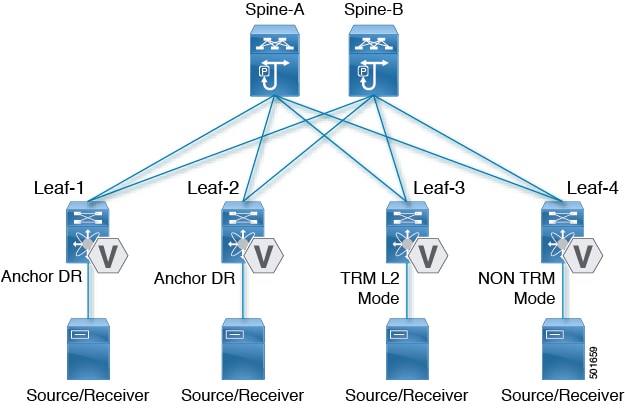
While BGP EVPN provides the control plane for unicast routing, ngMVPN provides scalable multicast routing functionality. It follows an “always route” approach where every edge device (VTEP) with distributed IP Anycast Gateway for unicast becomes a Designated Router (DR) for Multicast. Bridged multicast forwarding is only present on the edge-devices (VTEP) where IGMP snooping optimizes the multicast forwarding to interested receivers. Every other multicast traffic beyond local delivery is efficiently routed.

Figure 1. VXLAN EVPN TRM

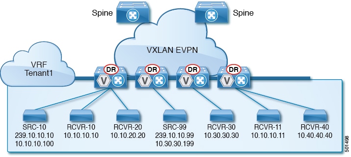
With TRM enabled, multicast forwarding in the underlay is leveraged to replicate VXLAN encapsulated routed multicast traffic. A Default Multicast Distribution Tree (Default-MDT) is built per-VRF. This is an addition to the existing multicast groups for Layer-2 VNI Broadcast, Unknown Unicast, and Layer-2 multicast replication group. The individual multicast group addresses in the overlay are mapped to the respective underlay multicast address for replication and transport. The advantage of using a BGP-based approach allows the VXLAN BGP EVPN fabric with TRM to operate as fully distributed Overlay Rendezvous-Point (RP), with the RP presence on every edge-device (VTEP).

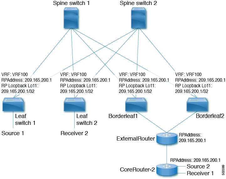
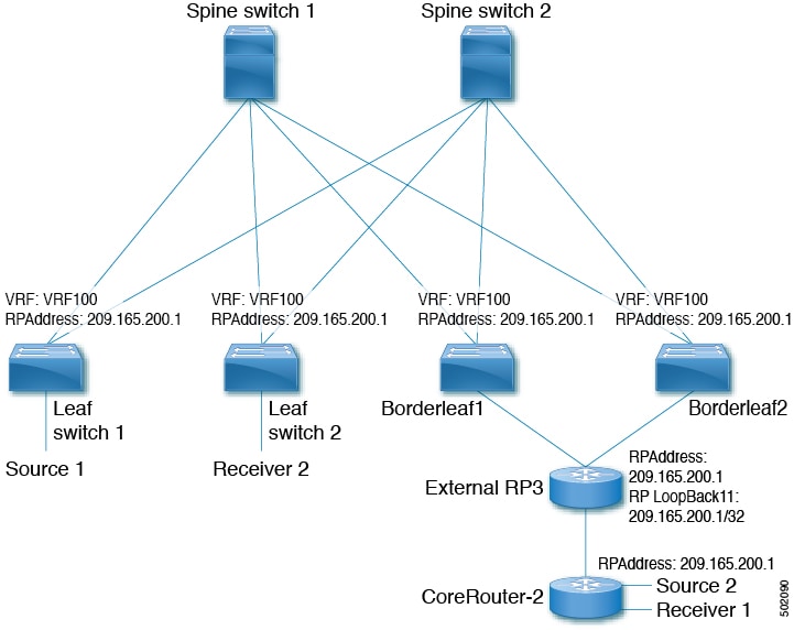
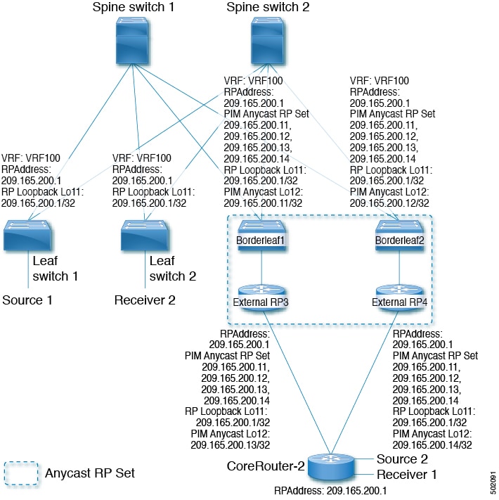
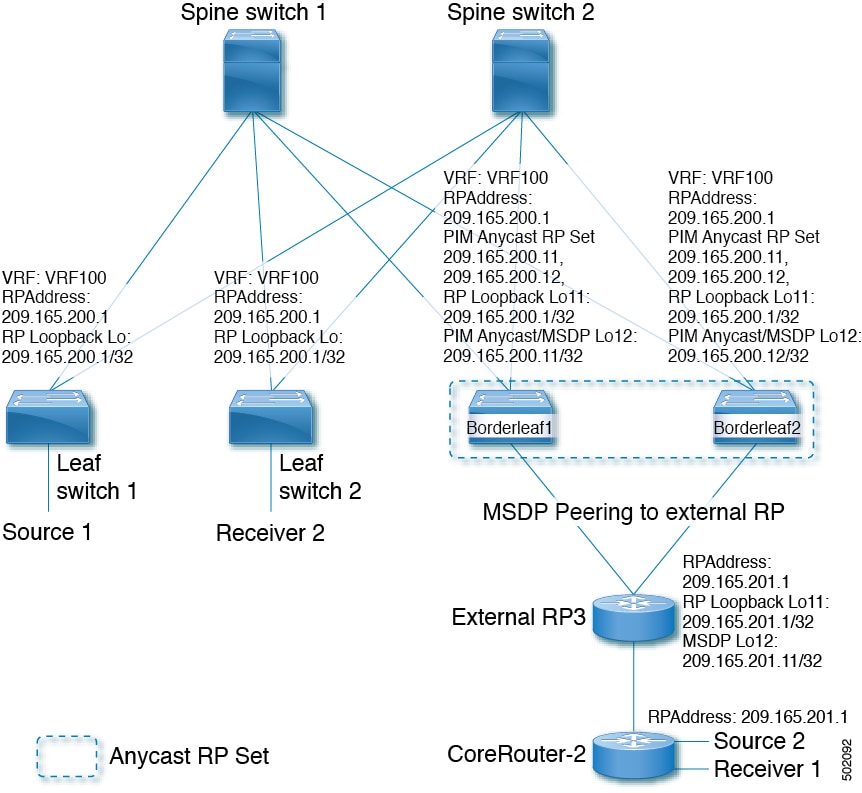
A multicast-enabled data center fabric is typically part of an overall multicast network. Multicast sources, receivers, and multicast rendezvous points, might reside inside the data center but might also be inside the campus or externally reachable via the WAN. TRM allows a seamless integration with existing multicast networks. It can leverage multicast rendezvous points external to the fabric. Furthermore, TRM allows for tenant-aware external connectivity using Layer-3 physical interfaces or subinterfaces.

About Tenant Routed Multicast Mixed Mode

Figure 2. TRM Layer2/Layer 3 Mixed Mode

Guidelines and Limitations for Tenant Routed Multicast

Tenant Routed Multicast (TRM) has the following guidelines and limitations:

  • With TRM enabled, advertise-pip and advertise virtual-rmac configurations are not supported.

  • The Guidelines and Limitations for VXLAN also apply to TRM.

  • With TRM enabled, FEX is not supported.

  • Beginning with Cisco NX-OS Release 7.0(3)I7(2), the VXLAN EVPN Multi-site Border Gateway (BGW) and TRM Border Leaf can co-exist on the same physical switch.

    • Within EVPN Multi-Site, TRM enabled East-West multicast traffic is not supported. In case the same external RP is used for multiple sites, overlapping multicast groups between sites must be avoided.

  • If TRM is configured, ISSU is disruptive.

  • TRM supports IPv4 multicast only.

  • TRM requires an IPv4 multicast-based underlay using PIM Any Source Multicast (ASM) which is also known as sparse mode.

  • TRM supports overlay PIM ASM and PIM SSM only. PIM BiDir is not supported in the overlay.

  • Coexistence of vPC and external PIM peering is not supported. A border leaf that is also a part of a vPC domain cannot hold TRM external connectivity for multicast.

  • Internal RP: The internal RP must be configured on all TRM-enabled VTEPs including the TRM border.

  • External RP: The external RP must be external to the TRM border.

    • The RP must be configured within the VRF pointing to the external RP IP address (static RP). This ensures that unicast and multicast routing is enabled to reach the external RP in the given VRF.

  • RP Everywhere: When configuring RP-Everywhere, the fabric TRM border and external RPs must be in a PIM Anycast-RP Set.

  • TRM supports multiple border nodes. Beginning with Cisco NX-OS Release 7.0(3)I7(6), reachability to an external RP via multiple border leaf switches is supported (ECMP). In prior releases, the external RP could only be reachable via a single border leaf (non ECMP).

Guidelines and Limitations for Layer 3 Tenant Routed Multicast

Layer 3 Tenant Routed Multicast (TRM) has the following configuration guidelines and limitations:

  • When configuring TRM VXLAN BGP EVPN, the following platforms are supported:

    • Cisco Nexus 9200, 9364C, 9300-EX, 9300-FX, and 9300-FX2

    • Cisco Nexus 9500 platform switches with 9700-EX line cards, 9700-FX line cards, or a combination of both line cards

  • Layer 3 mode is supported only for Cloud Scale Nexus 9000 Series switches.

  • Well known local scope multicast (224.0.0.0/24) is excluded from TRM and is bridged.

  • Whenever the NVE interface is brought down on the TRM border, the internal overlay RP (per VRF) must also be brought down.

Guidelines and Limitations for Layer 2/Layer 3 Tenant Routed Multicast (Mixed Mode)

Layer 2/Layer 3 Tenant Routed Multicast (TRM) has the following configuration guidelines and limitations:

  • All TRM Layer 2/Layer 3 configured switches must be Anchor DR. This is because in TRM Layer 2/Layer 3, you can have switches configured with TRM Layer 2 mode that co-exist in the same topology. This mode is necessary if non-TRM and Layer 2 TRM mode edge devices (VTEPs) are present in the same topology. 


  • All anchor DR must perform the overlay RP.

  • Cisco Nexus 9000 Series switches that operate in non-TRM or Layer 2 TRM mode are using Control-Plane based signalization (BGP IMET/SMET).

  • An extra loopback is required for Anchor DRs.

  • Non-TRM and Layer 2 TRM mode edge devices (VTEPs) require an IGMP snooping querier configured per multicast-enabled VLAN. Every non-TRM and Layer 2 TRM mode edge device (VTEP) requires this IGMP snooping querier configuration because in TRM multicast control-packets are not forwarded over VXLAN.

  • The IP address for the IGMP snooping querier can be re-used on non-TRM and Layer 2 TRM mode edge devices (VTEPs).

  • The IP address of the IGMP snooping querier in a VPC domain must be different on each VPC member device.

  • Whenever the NVE interface is brought down on the TRM border, the internal overlay RP (per VRF) must also be brought down.

  • Anchor DR is supported only on the following hardware platforms:

    • Cisco Nexus 9200, 9300-EX, 9300-FX, and 9300-FX2

    • Cisco Nexus 9500 platform switches with 9700-EX line cards, 9700-FX line cards, or a combination of both line cards.

Rendezvous Point for Tenant Routed Multicast

With TRM enabled Internal and External RP is supported. The following table displays the first release in which RP positioning is or is not supported.

RP Internal

RP External

PIM-Based RP Everywhere

TRM L2 Mode

N/A

N/A

N/A

TRM L3 Mode

7.0(3)I7(1), 9.2(x)

7.0(3)I7(4), 9.2(3)

Supported in 7.0(3)I7(x) releases starting from 7.0(3)I7(5)

Not supported in 9.2(x)

TRM L2L3 Mode

7.0(3)I7(1), 9.2(x)

N/A

N/A

Configuring a Rendezvous Point for Tenant Routed Multicast

For Tenant Routed Multicast, there are four rendezvous point options:

Configuring a Rendezvous Point Inside the VXLAN Fabric

Configure the loopback for the TRM VRFs with the following commands on all devices (VTEP). Ensure it is reachable within EVPN (advertise/redistribute).

Figure 3.

Procedure

  Command or Action Purpose

Step 1

configure terminal

Example:

switch# configure terminal

Enter configuration mode.

Step 2

interface loopback loopback_number

Example:

switch(config)# interface loopback 11

Configure the loopback interface on all distributed TRM enabled nodes.

Step 3

vrf member vxlan-number

Example:

switch(config-if)# vrf member vrf100

Configure VRF name.

Step 4

ip address ip-address

Example:

switch(config-if)# ip address 209.165.200.1/32

Specify IP address.

Step 5

ip pim sparse-mode

Example:

switch(config-if)# ip pim sparse-mode

Configure sparse-mode PIM on an interface.

Step 6

vrf context vrf-name

Example:

switch(config-if)# vrf context vrf100

Create a VXLAN tenant VRF.

Step 7

ip pim rp-address ip-address-of-router group-list group-range-prefix

Example:

switch(config-vrf# ip pim rp-address 209.165.200.1 group-list 224.0.0.0/4

The value of the ip-address-of-router parameters is that of the RP. The same IP address must be on all the edge devices (VTEPs) for a fully distributed RP.

Configuring an External Rendezvous Point

Configure the external rendezvous point (RP) IP address within the TRM VRFs on all devices (VTEP). In addition, ensure reachability of the external RP within the VRF via the border node. With TRM enabled and an external RP in use, ensure that only one routing path is active. Routing between the TRM fabric and the external RP must be via a single border leaf (non ECMP).

Procedure

  Command or Action Purpose

Step 1

configure terminal

Example:

switch# configure terminal

Enter configuration mode.

Step 2

vrf context vrf100

Example:

switch(config)# vrf context vrf100

Enter configuration mode.

Step 3

ip pim rp-address ip-address-of-router group-list group-range-prefix

Example:

switch(config-vrf)# ip pim rp-address 209.165.200.1 group-list 224.0.0.0/4

The value of the ip-address-of-router parameter is that of the RP. The same IP address must be on all of the edge devices (VTEPs) for a fully distributed RP.

Configuring RP Everywhere with PIM Anycast

RP Everywhere configuration with PIM Anycast solution.

For information about configuring RP Everywhere with PIM Anycast, see:

Configuring a TRM Leaf Node for RP Everywhere with PIM Anycast

Configuration of Tenant Routed Multicast (TRM) leaf node for RP Everywhere.

Procedure

  Command or Action Purpose

Step 1

configure terminal

Example:

switch# configure terminal

Enter configuration mode.

Step 2

interface loopback loopback_number

Example:

switch(config)# interface loopback 11

Configure the loopback interface on all VXLAN VTEP devices.

Step 3

vrf member vrf-name

Example:

switch(config-if)# vrf member vrf100

Configure VRF name.

Step 4

ip address ip-address

Example:

switch(config-if)# ip address 209.165.200.1/32

Specify IP address.

Step 5

ip pim sparse-mode

Example:

switch(config-if)# ip pim sparse-mode

Configure sparse-mode PIM on an interface.

Step 6

vrf context vxlan

Example:

switch(config-if)# vrf context vrf100

Create a VXLAN tenant VRF.

Step 7

ip pim rp-address ip-address-of-router group-list group-range-prefix

Example:

switch(config-vrf# ip pim rp-address 209.165.200.1 group-list 224.0.0.0/4

The value of the ip-address-of-router parameters is that of the RP. The same IP address must be on all the edge devices (VTEPs) for a fully distributed RP.

Configuring a TRM Border Leaf Node for RP Everywhere with PIM Anycast

Configuring the TRM Border Leaf Node for RP Anywhere with PIM Anycast.

Procedure

  Command or Action Purpose

Step 1

configure terminal

Example:

switch# configure terminal

Enter configuration mode.

Step 2

{ip | ipv6} pim evpn-border-leaf

Example:

switch(config)# ipv6 pim evpn-border-leaf

Configure VXLAN VTEP as TRM border leaf node,

Step 3

interface loopback loopback_number

Example:

switch(config)# interface loopback 11

Configure the loopback interface on all VXLAN VTEP devices.

Step 4

vrf member vrf-name

Example:

switch(config-if)# vrf member vrf100

Configure VRF name.

Step 5

ip address ip-address

Example:

switch(config-if)# ip address 209.165.200.1/32

Specify IP address.

Step 6

ipv6 pim sparse-mode

Example:

switch(config-if)# ipv6 pim sparse-mode

Configure sparse-mode PIM on an interface.

Step 7

interface loopback loopback_number

Example:

switch(config)# interface loopback 12

Configure the PIM Anycast set RP loopback interface.

Step 8

vrf member vxlan-number

Example:

switch(config-if)# vrf member vxlan-number

Configure VRF name.

Step 9

ipv6 address ipv6-address

Example:

switch(config-if)# ip address 209.165.200.11/32

Specify IP address.

Step 10

ipv6 pim sparse-mode

Example:

switch(config-if)# ipv6 pim sparse-mode

Configure sparse-mode PIM on an interface.

Step 11

vrf context vrf-name

Example:

switch(config-if)# vrf context vrf100

Create a VXLAN tenant VRF.

Step 12

ipv6 pim rp-address ipv6-address-of-router group-list group-range-prefix

Example:

switch(config-vrf)# ipv6 pim rp-address 2090:165:200::1 group ff1e::/16

The value of the ip-address-of-router parameters is that of the RP. The same IP address must be on all the edge devices (VTEPs) for a fully distributed RP.

Step 13

ipv6 pim anycast-rp anycast-rp-address address-of-rp

Example:

switch(config-vrf)# ipv6 pim anycast-rp 2090:165:2000::1 2090:165:2000::11

Configure PIM Anycast RP set.

Step 14

ipv6 pim anycast-rp anycast-rp-address address-of-rp

Example:

switch(config-vrf)# ipv6 pim anycast-rp 2090:165:2000::1 2090:165:2000::12

Configure PIM Anycast RP set.

Step 15

ipv6 pim anycast-rp anycast-rp-address address-of-rp

Example:

switch(config-vrf)# ipv6 pim anycast-rp 2090:165:2000::1 2090:165:2000::13

Configure PIM Anycast RP set.

Step 16

ipv6 pim anycast-rp anycast-rp-address address-of-rp

Example:

switch(config-vrf)# ipv6 pim anycast-rp 2090:165:2000::1 2090:165:2000::14

Configure PIM Anycast RP set.

Configuring an External Router for RP Everywhere with PIM Anycast

Use this procedure to configure an external router for RP Everywhere.

Procedure

  Command or Action Purpose

Step 1

configure terminal

Example:

switch# configure terminal

Enter configuration mode.

Step 2

interface loopback loopback_number

Example:

switch(config)# interface loopback 11

Configure the loopback interface on all VXLAN VTEP devices.

Step 3

vrf member vrf-name

Example:

switch(config-if)# vrf member vfr100

Configure VRF name.

Step 4

ip address ip-address

Example:

switch(config-if)# ip address 209.165.200.1/32

Specify IP address.

Step 5

ip pim sparse-mode

Example:

switch(config-if)# ip pim sparse-mode

Configure sparse-mode PIM on an interface.

Step 6

interface loopback loopback_number

Example:

switch(config)# interface loopback 12

Configure the PIM Anycast set RP loopback interface.

Step 7

vrf member vxlan-number

Example:

switch(config-if)# vrf member vrf100

Configure VRF name.

Step 8

ip address ip-address

Example:

switch(config-if)# ip address 209.165.200.13/32

Specify IP address.

Step 9

ip pim sparse-mode

Example:

switch(config-if)# ip pim sparse-mode

Configure sparse-mode PIM on an interface.

Step 10

vrf context vxlan

Example:

switch(config-if)# vrf context vrf100

Create a VXLAN tenant VRF.

Step 11

ip pim rp-address ip-address-of-router group-list group-range-prefix

Example:

switch(config-vrf)# ip pim rp-address 209.165.200.1 group-list 224.0.0.0/4

The value of the ip-address-of-router parameters is that of the RP. The same IP address must be on all the edge devices (VTEPs) for a fully distributed RP.

Step 12

ip pim anycast-rp anycast-rp-address address-of-rp

Example:

switch(config-vrf)# ip pim anycast-rp 209.165.200.1 209.165.200.11

Configure PIM Anycast RP set.

Step 13

ip pim anycast-rp anycast-rp-address address-of-rp

Example:

switch(config-vrf)# ip pim anycast-rp 209.165.200.1 209.165.200.12

Configure PIM Anycast RP set.

Step 14

ip pim anycast-rp anycast-rp-address address-of-rp

Example:

switch(config-vrf)# ip pim anycast-rp 209.165.200.1 209.165.200.13

Configure PIM Anycast RP set.

Step 15

ip pim anycast-rp anycast-rp-address address-of-rp

Example:

switch(config-vrf)# ip pim anycast-rp 209.165.200.1 209.165.200.14

Configure PIM Anycast RP set.

Configuring RP Everywhere with MSDP Peering

The following figure represents the RP Everywhere configuration with MSDP RP solution.

For information about configuring RP Everywhere with MSDP Peering, see:

Configuring a TRM Leaf Node for RP Everywhere with MSDP Peering

Configuring a TRM leaf node for RP Everywhere with MSDP peering.

Procedure

  Command or Action Purpose

Step 1

configure terminal

Example:

switch# configure terminal

Enter configuration mode.

Step 2

interface loopback loopback_number

Example:

switch(config)# interface loopback 11

Configure the loopback interface on all VXLAN VTEP devices.

Step 3

vrf member vrf-name

Example:

switch(config-if)# vrf member vrf100

Configure VRF name.

Step 4

ip address ip-address

Example:

switch(config-if)# ip address 209.165.200.1/32

Specify IP address.

Step 5

ip pim sparse-mode

Example:

switch(config-if)# ip pim sparse-mode

Configure sparse-mode PIM on an interface.

Step 6

vrf context vrf-name

Example:

switch(config-if)# vrf context vrf100

Create a VXLAN tenant VRF.

Step 7

ip pim rp-address ip-address-of-router group-list group-range-prefix

Example:

switch(config-vrf# ip pim rp-address 209.165.200.1 group-list 224.0.0.0/4

The value of the ip-address-of-router parameters is that of the RP. The same IP address must be on all the edge devices (VTEPs) for a fully distributed RP.

Configuring a TRM Border Leaf Node for RP Everywhere with MSDP Peering

Use this procedure to configure a TRM border leaf for RP Everywhere with PIM Anycast.

Procedure

  Command or Action Purpose

Step 1

configure terminal

Example:

switch# configure terminal

Enter configuration mode.

Step 2

feature msdp

Example:

switch(config)# feature msdp

Enable feature MSDP.

Step 3

ip pim evpn-border-leaf

Example:

switch(config)# ip pim evpn-border-leaf

Configure VXLAN VTEP as TRM border leaf node,

Step 4

interface loopback loopback_number

Example:

switch(config)# interface loopback 11

Configure the loopback interface on all VXLAN VTEP devices.

Step 5

vrf member vrf-name

Example:

switch(config-if)# vrf member vrf100

Configure VRF name.

Step 6

ip address ip-address

Example:

switch(config-if)# ip address 209.165.200.1/32

Specify IP address.

Step 7

ip pim sparse-mode

Example:

switch(config-if)# ip pim sparse-mode

Configure sparse-mode PIM on an interface.

Step 8

interface loopback loopback_number

Example:

switch(config)# interface loopback 12

Configure the PIM Anycast set RP loopback interface.

Step 9

vrf member vrf-name

Example:

switch(config-if)# vrf member vrf100

Configure VRF name.

Step 10

ip address ip-address

Example:

switch(config-if)# ip address 209.165.200.11/32

Specify IP address.

Step 11

ip pim sparse-mode

Example:

switch(config-if)# ip pim sparse-mode

Configure sparse-mode PIM on an interface.

Step 12

vrf context vrf-name

Example:

switch(config-if)# vrf context vrf100

Create a VXLAN tenant VRF.

Step 13

ip pim rp-address ip-address-of-router group-list group-range-prefix

Example:

switch(config-vrf)# ip pim rp-address 209.165.200.1 group-list 224.0.0.0/4

The value of the ip-address-of-router parameter is that of the RP. The same IP address must be on all the edge devices (VTEPs) for a fully distributed RP.

Step 14

ip pim anycast-rp anycast-rp-address address-of-rp

Example:

switch(config-vrf)# ip pim anycast-rp 209.165.200.1 209.165.200.11

Configure PIM Anycast RP set.

Step 15

ip pim anycast-rp anycast-rp-address address-of-rp

Example:

switch(config-vrf)# ip pim anycast-rp 209.165.200.1 209.165.200.12

Configure PIM Anycast RP set.

Step 16

ip msdp originator-id loopback

Example:

switch(config-vrf)# ip msdp originator-id loopback12

Configure MSDP originator ID.

Step 17

ip msdp peer ip-address connect-source loopback

Example:

switch(config-vrf)# ip msdp peer 209.165.201.11 connect-source loopback12

Configure MSDP peering between border node and external RP router.

Configuring an External Router for RP Everywhere with MSDP Peering

Procedure

  Command or Action Purpose

Step 1

configure terminal

Example:

switch# configure terminal

Enter configuration mode.

Step 2

feature msdp

Example:

switch(config)# feature msdp

Enable feature MSDP.

Step 3

interface loopback loopback_number

Example:

switch(config)# interface loopback 11

Configure the loopback interface on all VXLAN VTEP devices.

Step 4

vrf member vrf-name

Example:

switch(config-if)# vrf member vrf100

Configure VRF name.

Step 5

ip address ip-address

Example:

switch(config-if)# ip address 209.165.201.1/32

Specify IP address.

Step 6

ip pim sparse-mode

Example:

switch(config-if)# ip pim sparse-mode

Configure sparse-mode PIM on an interface.

Step 7

interface loopback loopback_number

Example:

switch(config)# interface loopback 12

Configure the PIM Anycast set RP loopback interface.

Step 8

vrf member vrf-name

Example:

switch(config-if)# vrf member vrf100

Configure VRF name.

Step 9

ip address ip-address

Example:

switch(config-if)# ip address 209.165.201.11/32

Specify IP address.

Step 10

ip pim sparse-mode

Example:

switch(config-if)# ip pim sparse-mode

Configure sparse-mode PIM on an interface.

Step 11

vrf context vrf-name

Example:

switch(config-if)# vrf context vrf100

Create a VXLAN tenant VRF.

Step 12

ip pim rp-address ip-address-of-router group-list group-range-prefix

Example:

switch(config-vrf)# ip pim rp-address 209.165.201.1 group-list 224.0.0.0/4

The value of the ip-address-of-router parameters is that of the RP. The same IP address must be on all the edge devices (VTEPs) for a fully distributed RP.

Step 13

ip msdp originator-id loopback12

Example:

switch(config-vrf)# ip msdp originator-id loopback12

Configure MSDP originator ID.

Step 14

ip msdp peer ip-address connect-source loopback12

Example:

switch(config-vrf)# ip msdp peer 209.165.200.11 connect-source loopback12

Configure MSDP peering between external RP router and all TRM border nodes.

Configuring Layer 3 Tenant Routed Multicast

This procedure enables the Tenant Routed Multicast (TRM) feature. TRM operates primarily in the Layer 3 forwarding mode for IP multicast by using BGP MVPN signaling. TRM in Layer 3 mode is the main feature and the only requirement for TRM enabled VXLAN BGP EVPN fabrics. If non-TRM capable edge devices (VTEPs) are present, the Layer 2/Layer 3 mode and Layer 2 mode have to be considered for interop.

To forward multicast between senders and receivers on the Layer 3 cloud and the VXLAN fabric on TRM vPC border leafs, the VIP/PIP configuration must be enabled. For more information, see Configuring VIP/PIP.


Note


TRM follows an always-route approach and hence decrements the Time to Live (TTL) of the transported IP multicast traffic.


Before you begin

VXLAN EVPN feature nv overlay and nv overlay evpn must be configured.

The rendezvous point (RP) must be configured.

Procedure

  Command or Action Purpose

Step 1

configure terminal

Example:

switch# configure terminal

Enter configuration mode.

Step 2

feature ngmvpn

Example:

switch(config)# feature ngmvpn

Enables the Next-Generation Multicast VPN (ngMVPN) control plane. New address family commands become available in BGP.

Step 3

ip igmp snooping vxlan

Example:

switch(config)# ip igmp snooping vxlan

Configure IGMP snooping for VXLANs.

Step 4

interface nve1

Example:

switch(config)# interface nve 1

Configure the NVE interface.

Step 5

member vni vni-range associate-vrf

Example:

switch(config-if-nve)# member vni 200100 associate-vrf

Configure the virtual network identifier. The range of vni-range is from 1 to 16,777,214.

Step 6

mcast-group ip-prefix

Example:

switch(config-if-nve-vni)# mcast-group 225.3.3.3

Builds the default multicast distribution tree for the VRF VNI (Layer 3 VNI).

The multicast group is used in the underlay (core) for all multicast routing within the associated Layer 3 VNI (VRF).

Note


We recommend that underlay multicast groups for Layer 2 VNI, default MDT, and data MDT not be shared. Use separate, non-overlapping groups.

Step 7

exit

Example:

switch(config-if-nve-vni)# exit

Exits command mode.

Step 8

exit

Example:

switch(config-if)# exit

Exits command mode.

Step 9

router bgp 100

Example:

switch(config)# router bgp 100

Set autonomous system number.

Step 10

exit

Example:

switch(config-router)# exit

Exits command mode.

Step 11

neighbor ip-addr

Example:

switch(config-router)# neighbor 1.1.1.1 

Configure IP address of the neighbor.

Step 12

address-family ipv4 mvpn

Example:

switch(config-router-neighbor)# address-family ipv4 mvpn

Configure multicast VPN.

Step 13

send-community extended

Example:

switch(config-router-neighbor-af)# send-community extended

Enables ngMVPN for address family signalization. The send community both command ensures both standard and extended communities are exchanged for this address family.

Step 14

exit

Example:

switch(config-router-neighbor-af)# exit

Exits command mode.

Step 15

exit

Example:

switch(config-router)# exit

Exits command mode.

Step 16

vrf context vrf_name

Example:

switch(config-router)#vrf context vrf100

Configure VRF name.

Step 17

ip pim rp-address ip-address-of-router group-list group-range-prefix

Example:

switch(config-vrf)# ip pim rp-address 99.99.99.1 group-list 226.0.0.0/8

The value of the ip-address-of-router parameter is that of the RP. The same IP address must be on all of the edge devices (VTEPs) for a fully distributed RP.

For overlay RP placement options, see the Configuring a Rendezvous Point for Tenant Routed Multicast section.

Step 18

address-family ipv4 unicast

Example:

switch(config-vrf)# address-family ipv4 unicast

Configure unicast address family.

Step 19

route-target both auto mvpn

Example:

switch(config-vrf-af-ipv4)# route-target both auto mvpn

Defines the BGP route target that is added as an extended community attribute to the customer multicast (C_Multicast) routes (ngMVPN route type 6 and 7).

Auto route targets are constructed by the 2-byte Autonomous System Number (ASN) and Layer 3 VNI.

Step 20

ip multicast overlay-spt-only

Example:

switch(config)# ip multicast overlay-spt-only

Add the ip multicast overlay-spt-only command on all MVPN-enabled Cisco Nexus 9000 Series switches (typically leaf node).

Step 21

interface vlan_id

Example:

switch(config)# interface vlan11

Configures the first-hop gateway (distributed anycast gateway for the Layer 2 VNI. No router PIM peering must ever happen with this interface.

Step 22

no shutdown

Example:

switch(config-if)# no shutdown

Disables an interface.

Step 23

vrf member vrf-num

Example:

switch(config-if)# vrf member vrf100

Configure VRF name.

Step 24

ip address ip_address

Example:

switch(config-if)# ip address 11.1.1.1/24

Configure IP address.

Step 25

ip pim sparse-mode

Example:

switch(config-if)# ip pim sparse-mode

Enables IGMP and PIM on the SVI. This is required is multicast sources and/or receivers exist in this VLAN.

Step 26

fabric forwarding mode anycast-gateway

Example:

switch(config-if)# fabric forwarding mode anycast-gateway

Configure Anycast Gateway Forwarding Mode.

Step 27

ip pim neighbor-policy route-map-name

Example:

switch(config-if)# ip pim neighbor-policy route-map1

Creates an IP PIM neighbor policy with a suitable route-map to deny any IPv4 addresses, preventing PIM from establishing PIM neighborship on the L2VNI SVI.

Note


Do not use Distributed Anycast Gateway for PIM Peerings.

Step 28

exit

Example:

switch(config-if)# exit

Exits command mode.

Step 29

interface vlan_id

Example:

switch(config)# interface vlan100

Configure Layer 3 VNI.

Step 30

no shutdown

Example:

switch(config-if)# no shutdown

Disable an interface.

Step 31

vrf member vrf100

Example:

switch(config-if)# vrf member vrf100

Configure VRF name.

Step 32

ip forward

Example:

switch(config-if)# ip forward

Enable IP forwarding on interface.

Step 33

ip pim sparse-mode

Example:

switch(config-if)# ip pim sparse-mode

Configure sparse-mode PIM on interface. There is no PIM peering happening in the Layer-3 VNI, but this command must be present for forwarding.

Configuring TRM on the VXLAN EVPN Spine

This procedure enables Tenant Routed Multicast (TRM) on a VXLAN EVPN spine switch.

Before you begin

The VXLAN BGP EVPN spine must be configured. See Configuring BGP for EVPN on the Spine.

Procedure

  Command or Action Purpose

Step 1

configure terminal

Example:

switch# configure terminal

Enter configuration mode.

Step 2

route-map permitall permit 10

Example:

switch(config)# route-map permitall permit 10

Configure the route-map.

Note


The route-map keeps the next-hop unchanged for EVPN routes

  • Required for eBGP

  • Options for iBGP

Step 3

set ip next-hop unchanged

Example:

switch(config-route-map)# set ip next-hop unchanged

Set next hop address.

Note


The route-map keeps the next-hop unchanged for EVPN routes

  • Required for eBGP

  • Options for iBGP

Step 4

exit

Example:

switch(config-route-map)# exit

Return to exec mode.

Step 5

router bgp [autonomous system] number

Example:

switch(config)# router bgp 65002

Specify BGP.

Step 6

address-family ipv4 mvpn

Example:

switch(config-router)# address-family ipv4 mvpn

Configure the address family IPv4 MVPN under the BGP.

Step 7

retain route-target all

Example:

switch(config-router-af)# retain route-target all

Configure retain route-target all under address-family IPv4 MVPN [global].

Note


Required for eBGP. Allows the spine to retain and advertise all MVPN routes when there are no local VNIs configured with matching import route targets.

Step 8

neighbor ip-address [remote-as number]

Example:

switch(config-router-af)# neighbor 100.100.100.1 

Define neighbor.

Step 9

address-family ipv4 mvpn

Example:

switch(config-router-neighbor)# address-family ipv4 mvpn

Configure address family IPv4 MVPN under the BGP neighbor.

Step 10

disable-peer-as-check

Example:

switch(config-router-neighbor-af)# disable-peer-as-check

Disables checking the peer AS number during route advertisement. Configure this parameter on the spine for eBGP when all leafs are using the same AS but the spines have a different AS than leafs.

Note


Required for eBGP.

Step 11

rewrite-rt-asn

Example:

switch(config-router-neighbor-af)# rewrite-rt-asn

Normalizes the outgoing route target's AS number to match the remote AS number. Uses the BGP configured neighbors remote AS. The rewrite-rt-asn command is required if the route target auto feature is being used to configure EVPN route targets.

Step 12

send-community extended

Example:

switch(config-router-neighbor-af)# send-community extended

Configures community for BGP neighbors.

Step 13

route-reflector-client

Example:

switch(config-router-neighbor-af)# route-reflector-client

Configure route reflector.

Note


Required for iBGP with route-reflector.

Step 14

route-map permitall out

Example:

switch(config-router-neighbor-af)# route-map permitall out

Applies route-map to keep the next-hop unchanged.

Note


Required for eBGP.

Configuring Tenant Routed Multicast in Layer 2/Layer 3 Mixed Mode

This procedure enables the Tenant Routed Multicast (TRM) feature. This enables both Layer 2 and Layer 3 multicast BGP signaling. This mode is only necessary if non-TRM edge devices (VTEPs) are present in the same such as Cisco Nexus 9000 Series switches (1st generation) or Cisco Nexus 7000 Series switches. Only the Cisco Nexus 9000-EX and 9000-FX switches can do Layer 2/Layer 3 mode (Anchor-DR).

To forward multicast between senders and receivers on the Layer 3 cloud and the VXLAN fabric on TRM vPC border leafs, the VIP/PIP configuration must be enabled. For more information, see Configuring VIP/PIP.

All Cisco Nexus 9300-EX and 9300-FX platform switches must be in Layer 2/Layer 3 mode.

Before you begin

VXLAN EVPN must be configured.

The rendezvous point (RP) must be configured.

Procedure

  Command or Action Purpose

Step 1

configure terminal

Example:

switch# configure terminal

Enter configuration mode.

Step 2

feature ngmvpn

Example:

switch(config)# feature ngmvpn

Enables the Next-Generation Multicast VPN (ngMVPN) control plane. New address family commands become available in BGP.

Step 3

advertise evpn multicast

Example:

switch(config)# advertise evpn multicast

Advertises IMET and SMET routes into BGP EVPN towards non-TRM capable switches.

Step 4

ip igmp snooping vxlan

Example:

switch(config)# ip igmp snooping vxlan

Configure IGMP snooping for VXLANs.

Step 5

ip multicast overlay-spt-only

Example:

switch(config)# ip multicast overlay-spt-only

Gratuitously originate (S,A) route when source is locally connected.

Step 6

ip multicast overlay-distributed-dr

Example:

switch(config)# ip multicast overlay-distributed-dr

Enables distributed anchor DR function on this VTEP.

Step 7

interface nve1

Example:

switch(config)# interface nve 1

Configure the NVE interface.

Step 8

member vni vni-range associate-vrf

Example:

switch(config-if-nve)# member vni 200100 associate-vrf

Configure the virtual network identifier. The range of vni-range is from 1 to 16,777,214.

Step 9

mcast-group ip-prefix

Example:

switch(config-if-nve-vni)# mcast-group 225.3.3.3

Configures the multicast group on distributed anchor DR.

Step 10

exit

Example:

switch(config-if-nve-vni)# exit

Exits command mode.

Step 11

interface loopback loopback_number

Example:

switch(config-if-nve)# interface loopback 10

Configure the loopback interface on all distributed anchor DR devices.

Step 12

ip address ip_address

Example:

switch(config-if)# ip address 100.100.1.1/32

Configure IP address. This IP address is the same on all distributed anchor DR.

Step 13

ip router ospf process-tag area ospf-id

Example:

switch(config-if)# ip router ospf 100 area 0.0.0.0

OSPF area ID in IP address format.

Step 14

ip pim sparse-mode

Example:

switch(config-if)# ip pim sparse-mode

Configure sparse-mode PIM on interface.

Step 15

interface nve1

Example:

switch(config-if)# interface nve1

Configure NVE interface.

Step 16

shutdown

Example:

switch(config-if-nve)# shutdown

Disable the interface.

Step 17

mcast-routing override source-interface loopback int-num

Example:

switch(config-if-nve)# mcast-routing override source-interface loopback 10

Enables that TRM is using a different source-interface interface than the VTEPs default source-interface.

The loopback2 variable must be configured on every TRM-enabled VTEP (Anchor DR) in the underlay. This loopback and the respective override command is needed to serve TRM VTEPs in co-existence with non-TRM VTEPs. The loopback has to be configured with the same IP address.

Step 18

exit

Example:

switch(config-if-nve)# exit

Exits command mode.

Step 19

router bgp 100

Example:

switch(config)# router bgp 100

Set autonomous system number.

Step 20

neighbor ip-addr

Example:

switch(config-router)# neighbor 1.1.1.1 

Configure IP address of the neighbor.

Step 21

address-family ipv4 mvpn

Example:

switch(config-router-neighbor)# address-family ipv4 mvpn

Configure multicast VPN.

Step 22

send-community extended

Example:

switch(config-router-neighbor-af)# send-community extended

Send community attribute.

Step 23

exit

Example:

switch(config-router-neighbor-af)# exit

Exits command mode.

Step 24

exit

Example:

switch(config-router)# exit

Exits command mode.

Step 25

vrf vrf_name vrf100

Example:

switch(config)# vrf context vrf100

Configure VRF name.

Step 26

ip pim rp-address ip-address-of-router group-list group-range-prefix

Example:

switch(config-vrf)# ip pim rp-address 99.99.99.1 group-list 226.0.0.0/8

The value of the ip-address-of-router parameter is that of the RP. The same IP address must be on all of the edge devices (VTEPs) for a fully distributed RP.

For overlay RP placement options, see the Configuring a Rendezvous Point for Tenant Routed Multicast - Internal RP section.

Step 27

address-family ipv4 unicast

Example:

switch(config-vrf)# address-family ipv4 unicast

Configure unicast address family.

Step 28

route-target both auto mvpn

Example:

switch(config-vrf-af-ipv4)# route-target both auto mvpn

Specify target for mvpn routes.

Step 29

exit

Example:

switch(config-vrf-af-ipv4)# exit

Exits command mode.

Step 30

exit

Example:

switch(config-vrf)# exit

Exits command mode.

Step 31

interface vlan_id

Example:

switch(config)# interface vlan11

Configure Layer 2 VNI.

Step 32

no shutdown

Example:

switch(config-if)# no shutdown

Disable an interface.

Step 33

vrf member vrf100

Example:

switch(config-if)# vrf member vrf100

Configure VRF name.

Step 34

ip address ip_address

Example:

switch(config-if)# ip address 11.1.1.1/24

Configure IP address.

Step 35

ip pim sparse-mode

Example:

e
switch(config-if)# ip pim sparse-mode

Configure sparse-mode PIM on interface.

Step 36

fabric forwarding mode anycast-gateway

Example:

switch(config-if)# fabric forwarding mode anycast-gateway

Configure Anycast Gateway Forwarding Mode.

Step 37

ip pim neighbor-policy route-map-name

Example:

switch(config-if)# ip pim neighbor-policy route-map1

Creates an IP PIM neighbor policy with a suitable route-map to deny any IPv4 addresses, preventing PIM from establishing PIM neighborship on the L2VNI SVI.

Step 38

exit

Example:

switch(config-if)# exit

Exits command mode.

Step 39

interface vlan_id

Example:

switch(config)# interface vlan100

Configure Layer 3 VNI.

Step 40

no shutdown

Example:

switch(config-if)# no shutdown

Disable an interface.

Step 41

vrf member vrf100

Example:

switch(config-if)# vrf member vrf100

Configure VRF name.

Step 42

ip forward

Example:

switch(config-if)# ip forward

Enable IP forwarding on interface.

Step 43

ip pim sparse-mode

Example:

switch(config-if)# ip pim sparse-mode

Configure sparse-mode PIM on interface.

Configuring Layer 2 Tenant Routed Multicast

This procedure enables the Tenant Routed Multicast (TRM) feature. This enables Layer 2 multicast BGP signaling.

IGMP Snooping Querier must be configured per multicast-enabled VXLAN VLAN on all Layer-2 TRM leaf switches.

Before you begin

VXLAN EVPN must be configured.

Procedure

  Command or Action Purpose

Step 1

configure terminal

Example:

switch# configure terminal

Enter configuration mode.

Step 2

feature ngmvpn

Example:

switch(config)# feature ngmvpn

Enables EVPN/MVPN feature.

Step 3

advertise evpn multicast

Example:

switch(config)# advertise evpn multicast

Advertise L2 multicast capability.

Step 4

ip igmp snooping vxlan

Example:

switch(config)# ip igmp snooping vxlan

Configure IGMP snooping for VXLANs.