Cisco Data Center Networking Blueprint for AI/ML Applications
Available Languages
Bias-Free Language
The documentation set for this product strives to use bias-free language. For the purposes of this documentation set, bias-free is defined as language that does not imply discrimination based on age, disability, gender, racial identity, ethnic identity, sexual orientation, socioeconomic status, and intersectionality. Exceptions may be present in the documentation due to language that is hardcoded in the user interfaces of the product software, language used based on RFP documentation, or language that is used by a referenced third-party product. Learn more about how Cisco is using Inclusive Language.
- US/Canada 800-553-2447
- Worldwide Support Phone Numbers
- All Tools
 Feedback
 Feedback
Want free trials and special offers on data center and cloud networking products? Right this way.
RoCEv2 as Transport for AI Clusters
AI Clusters Require Lossless Networks
Explicit Congestion Notification (ECN)
How to Manage Congestion Efficiently in AI/ML Cluster Networks
Using ECN and PFC Together to Build Lossless Ethernet Networks
Using Approximate Fair Drop (AFD)
How Visibility into Network Behavior Improves Transport and Troubleshooting
Using Nexus Dashboard Insights
Network Design to Accommodate the Best Performance of an AI/ML Cluster
Building a Shared 100Gbps Network
Building a 400Gbps Back-End Network
Using Cisco Nexus Dashboard Fabric Controller to Automate Your AI/ML Network
Artificial intelligence and machine learning (AI/ML) applications are becoming increasingly commonplace in data centers. Machine learning, a subset of AI, is one of the most common applications. ML is the ability of computer systems to learn to make decisions and predictions from observations and data.
Today, widely available GPU-accelerated servers create the flexibility to design and train custom deep neural networks. The availability of better server hardware along with commonly used programming languages such as Python and C/C++, and frameworks such as PyTorch, TensorFlow, and JAX, which are built to take advantage of GPUs natively, have simplified the building of GPU-accelerated ML applications. These applications can be used for many purposes such as advanced medical research, computer-aided drug discovery, natural language processing, self-driving vehicles, making shopping recommendations, and recognizing images in a video stream.
In many cases, building ML applications starts with training deep neural networks with large datasets across multiple iterations. Neural networks take advantage of GPU clusters that can be made up of thousands of GPUs, usually with several GPUs per server. These servers often have dual 100Gb network interface cards (NICs) connected to separate switches, with strict networking requirements.
Deep learning models have highly flexible architectures that allow them to learn directly from raw data. Training deep learning clusters with large data sets can increase their predictive accuracy. As expected, these applications generate high volumes of data that must be collected and processed in real time and are shared across multiple devices sometimes numbering in the thousands. Inference frameworks take the knowledge from trained neural network models and apply them to new data to predict the outcomes. Inference clusters can have different requirements and are optimized for performance. Deep learning systems are optimized to handle large amounts of data to process and re-evaluate results. Inference systems may use smaller data sets but be hyper-scaled to many devices. Examples of this are applications in smart phones or self-driving cars.
Some of the learning cycles discussed above can take days, or even weeks, to complete with very large data sets. When communication between the server clusters involved in learning cycles has high latency, or packet drops, the learning job can take much longer to complete, or in some cases fail. Because of this, AI workloads have stringent infrastructure requirements.
AI applications take advantage of--and expect--low latency, lossless networks. To achieve this, network administrators need to deploy the right hardware and software features, along with a configuration that supports AI application needs. AI applications also need networks that can provide visibility into hot spots so they can be tuned as necessary. Finally, AI applications should take advantage of automation frameworks to make sure the entire network fabric is configured correctly and there is no configuration drift.
The Cisco Nexus 9000 switches have the hardware and software capabilities available today to provide the right latency, congestion management mechanisms, and telemetry to meet the requirements of AI/ML applications. Coupled with tools such as Cisco Nexus Dashboard Insights for visibility and Nexus Dashboard Fabric Controller for automation, Cisco Nexus 9000 switches become ideal platforms to build a high-performance AI/ML network fabric.
This document is intended to provide a best practice blueprint for building a modern network environment that will allow AI/ML workloads to run at their best using shipped hardware and software features. See also the Cisco Validated Design for Data Center Networking Blueprint for AI/ML Applications, which contains configuration examples for this blueprint.
RoCEv2 as Transport for AI Clusters
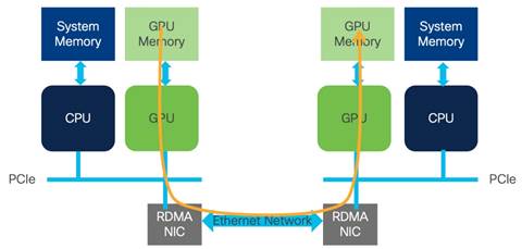
Remote direct memory access (RDMA) is a well-known technology used for high performance computing (HPC) and storage networking environments. The advantages of RDMA are the high throughput and low latency transfer of information between compute nodes at the memory-to-memory level, without burdening the CPU. This transfer function is offloaded to the network adapter hardware to bypass the operating system software network stack. This technology also has the advantage of reduced power requirements.
In its first application, InfiniBand (IB) brought the full benefits of RDMA to the market, providing high throughput and CPU bypass that provided lower latency. InfiniBand also built congestion management into the protocol. These benefits led InfiniBand to become the high-performance computing transport of choice.
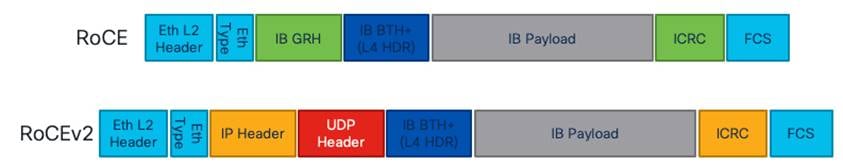
For enterprise networks that required HPC workloads, InfiniBand led to the design of a separate network to leverage all its benefits. These purpose-built networks brought additional cost and complexity to the enterprise. RDMA provides several implementations for network transport. One of them is Ethernet based, namely RDMA over Converged Ethernet (RoCE).
RoCE is an InfiniBand Trade Association (IBTA) standard that was first introduced in 2010 and works only on the same Layer 2 broadcast domain. RoCE version 2 was introduced in 2014 and allows the routing of traffic. RoCE is an extension of InfiniBand with Ethernet forwarding. RoCEv2 encapsulates IB transport in Ethernet, IP, and UDP headers, so it can be routed over Ethernet networks.
Ethernet is ubiquitous in enterprise data centers. Network administrators are very familiar with ethernet, and that is a big benefit of the technology. In addition to that, affordability and the possibility to create a "converged" fabric that carries regular enterprise traffic, along with RDMA workloads, is very appealing to customers. This is one of the reasons RoCEv2 is being implemented in data center networks. RoCEv2 requires lossless transport. This can be achieved by using explicit congestion notification (ECN) and priority flow control (PFC) congestion avoidance algorithms.
In AI/ML clusters, RDMA is used to communicate memory-to-memory between GPUs over the network. This implementation is called GPUDirect RDMA. RoCEv2 is an excellent transport for GPUDirect RDMA.
AI Clusters Require Lossless Networks
Explicit Congestion Notification (ECN)
In situations where congestion information needs to be propagated end-to-end, ECN can be used for congestion management. ECN is marked in the network node where congestion is experienced inside the IP header type of service (TOS) field in the 2 least significant bits. When a receiver gets a packet with the ECN congestion experience bits set to 0x11, it generates and sends a congestion notification packet (CNP) back to the sender. When the sender receives the congestion notification, it slows down the flow that matches the notification. This end-to-end process is built in the data path, and as such is an efficient way to manage congestion. An example of how ECN works is provided later in this document.
| ECN bits |
ECN Behavior |
| 0x00 |
Non-ECN Capable |
| 0x10 |
ECN Capable Transport (0) |
| 0x01 |
ECN Capable Transport (1) |
| 0x11 |
Congestion Encountered |
Table 1. ECN Bit values used by network devices and end hosts.
Priority Flow Control was introduced in Layer 2 networks as the primary mechanism to enable lossless Ethernet. Flow control was driven by the class of service (COS) value in the Layer 2 frame, and congestion is signaled and managed using pause frames, and a pause mechanism. However, building scalable Layer 2 networks can be a challenging task for network administrators. Because of this, network designs have mostly evolved into Layer 3 routed fabrics.
As RoCEv2 can be routed, PFC was adjusted to work with differentiated services code point (DSCP) priorities to signal congestion between routed hops in the network. DSCP is a mechanism used for classifying network traffic on IP networks. It uses the 6-bit differentiated services field in the IP header for packet classification purposes. Using Layer 3 marking enables traffic to maintain classification semantics across routers. Since PFC frames use link local addressing, the network devices can receive and perform pause signaling for both routed and switched traffic. PFC is transmitted per-hop, from the place of congestion to the source of the traffic. This step-by-step behavior could take time to be propagated to the source. PFC is used as the primary tool to manage congestion for RoCEv2 transport. An example of how PFC works is provided later in this document.
Cisco Nexus 9000 switches support both PFC congestion management and ECN marking with either weighted random early detection (WRED) or approximate fair drop (AFD) to indicate congestion in the network node.
How to Manage Congestion Efficiently in AI/ML Cluster Networks
PFC and ECN complement each other to provide the most efficient congestion management. Together, they provide the highest throughput and lowest latency penalty during congestion. They each play an important role in building a lossless Ethernet network. To understand their complementary roles, we will first look at how ECN signaling works, followed by an example of PFC congestion control in a two-tier (spine switch and leaf switch) network.
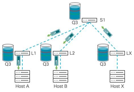
ECN and PFC need to be enabled end-to-end in the system through the quality of service (QoS) configuration. Both end hosts and network nodes must participate in ECN and PFC to enable lossless traffic capabilities. ![]()
ECN is a feature that is used between two ECN-enabled endpoints. Nexus 9000 switches can mark packets with ECN bits in case of network congestion. An ECN-capable network node uses a congestion avoidance algorithm to check the amount of the queue being used, and after a specified threshold is reached it will mark traffic contributing to the congestion. In this example, weighted random early detection (WRED) is used to indicate congestion and mark traffic with ECN bits.
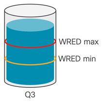
WRED on Cisco Nexus 9000 is done on a per-queue level. In the queue, two thresholds are set. The WRED minimum threshold is lower in the buffer utilization and indicates minor congestion that could grow. As buffer utilization continues to grow, when it reaches the minimum threshold, WRED marks an amount of outgoing packets leaving the queue. How many packets depends on the drop probability value in the WRED configuration, and on Cisco Nexus 9000 this is represented as percentage of all outgoing packets. For example, if the drop probability parameters set to 10, it signifies that 10% of all outgoing packets will be marked. If this does not alleviate the congestion, buffer utilization will grow in the queue and reach the WRED maximum threshold. After crossing the WRED maximum threshold, the switch marks ECN on every outgoing packet for the queue. This WRED ECN mechanism allows endpoints to learn about congestion and react to it, which is explained in the next example.
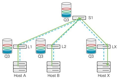
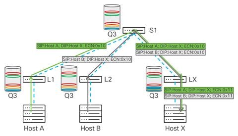
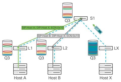
In this example, we have a two-tier network, and hosts A and B are sending data to host X.
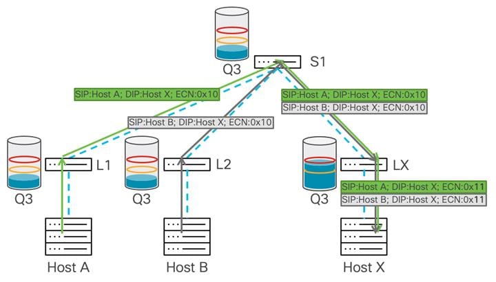
Congestion occurs on Leaf X, as there is more bandwidth from the spine switch than to host X and the port connected to host X is oversubscribed. Buffer usage will start building up on Leaf X. After the buffer reaches the WRED minimum threshold, the leaf switch starts marking several of the packets’ ECN field with a 0x11 value to indicate congestion in the data path.
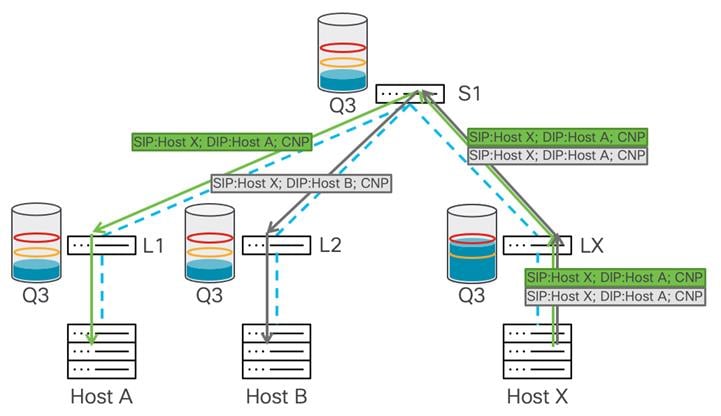
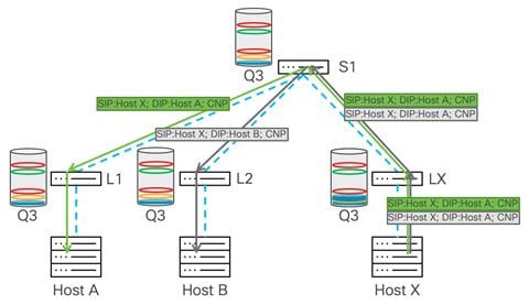
After the destination (host X) receives the marked packet, it learns that congestion is happening in the data path and generates a CNP packet to the source host from whom it received the now-marked packet.
As only some amounts of the data packets were marked with congestion experienced bits, the source reduces traffic throughput for that flow and continues to send packets. If congestion continues and the buffer usage rises over the WRED maximum threshold, the switch marks every packet with congestion experienced bits. This means that the sender receives many CNP packets, and based on its algorithm it should drastically reduce the data rate transmission toward the destination. This mitigates congestion and the buffer should start draining. As that happens, the traffic rate should rise until the next time congestion is signaled.
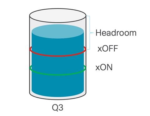
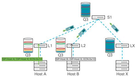
When PFC is enabled on the Cisco Nexus 9000 switch, a class of service is dedicated to lossless transport. Traffic in this class is treated differently than traffic in other classes. Any port on the Cisco Nexus 9000 switch configured with PFC is allocated a dedicated no-drop queue and dedicated buffer for that queue.
To provide lossless capabilities, the queue has two thresholds. The xOFF threshold is set higher in the buffer and this is the point in the buffer utilization where a PFC frame is generated and sent toward the source of the traffic. After the buffer starts draining and falls below the xON threshold, this is where pause frames are halted and no longer sent toward the senders. This is the point when the system believes that congestion is over.
The following example shows how PFC manages congestion. Leaf X receives traffic coming from hosts A and B. This leads to congestion on the port toward host X. At this point, the switch uses its dedicated buffer to absorb incoming traffic. The traffic is buffered by Leaf X, and after the xOFF threshold is reached it will send a pause frame to the upstream hop, in this diagram the spine switch S1.
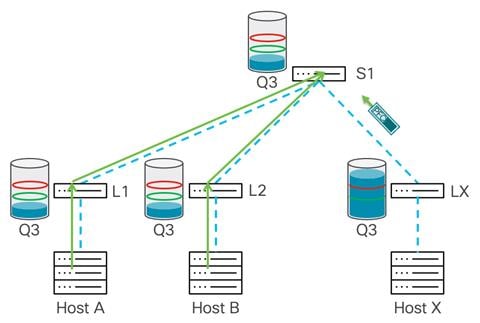
After spine switch S1 receives the pause frame, S1 stops transmitting traffic, which prevents further congestion on the Leaf X. At the same time, S1 starts buffering traffic in the no-drop queue, and after the buffer reaches the xOFF threshold, it sends pause frames down to the upstream devices, Leaf 1 and Leaf 2, as both are sending traffic toward the spine switch.
This hop-by-hop propagation of pause behavior continues, the leaf switches receive pause frames, and the switches pause transmission to the spine swtich and start buffering traffic. This leads to Leaf 1 and 2 sending pause frames to host A and B, respectively.
After the senders receive a pause frame, the stream slows down. This allows the buffers to be drained on all the switches in the network. After each device reaches the xON threshold, that device stops propagating pause frames. After the congestion is mitigated and pause frames are no longer sent, Host X starts receiving traffic again.
This pause process repeats from the congestion point all the way to the sender every time congestion occurs in the network, or at an endpoint where PFC is enabled. As shown in the example, this process requires that all devices in the path receive a pause frame before they stop sending. This process is used to prevent packet drops.
In rare instances, a PFC storm can occur when a misbehaving host continuously transmits PFC frames. This behavior can saturate the buffers on all the network nodes, and after it reaches all the end hosts it can completely stop the network. To prevent PFC storms, you should use the PFC watchdog feature. A PFC watchdog interval is configured to detect whether packets in a no-drop queue are drained within a specified time period. If the time period is exceeded, all outgoing packets are dropped on interfaces that match the PFC queue that is not being drained to prevent a PFC deadlock in the network.
Using ECN and PFC Together to Build Lossless Ethernet Networks
As represented in the previous examples, both ECN and PFC by themselves can manage congestion very well. Working together, they can be even more effective. ECN can react first to mitigate congestion. If ECN does not react fast enough and buffer utilization continues to build up, PFC behaves as a fail-safe and prevents traffic drops. This is the most efficient way to manage congestion and build lossless Ethernet networks.
This collaborative process between PFC and ECN where they managed congestion together is called Data Center Quantized Congestion Notification (DCQCN) and is developed for RoCE networks.
Working together, PFC and ECN provide efficient end-to-end congestion management. When the system is experiencing minor congestion where buffer usage is moderate, WRED with ECN manages the congestion seamlessly. In cases where congestion is more severe or caused by microbursts producing high usage of buffers, PFC is triggered, and that congestion is managed. For both WRED and ECN to work as described, you should set appropriate thresholds. In the following example, the WRED minimum and maximum threshold are set for lower buffer utilization to mitigate congestion first, and the PFC threshold is set higher as a safety net to mitigate congestion after ECN. Both ECN and PFC work on a queue that is no-drop, providing lossless transport.
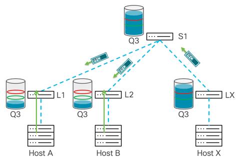
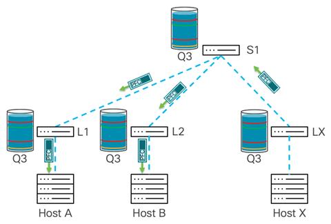
In this example both Host A and B send traffic to Host X. As leaf uplinks provide enough bandwidth for all traffic to arrive to Leaf X, the congestion point is on the outgoing interface toward Host X.
In the figure, both WRED ECN and PFC are conffigured on no-drop queue on all switches in the network. Leaf X experiences buffer build up that goes over the WRED min threshold, and the switch will mark the IP header with ECN bits.
The traffic reaches the minimum WRED threshold in Leaf X. The WRED in Leaf X reacts by marking traffic with ECN 0x11 bits. After Host X receives this traffic, it sends back CNP packets to Hosts A and B.
Sometimes WRED ECN may not be enough and a high PFC threshold will help to further mitigate congestion. Traffic still comes from multiple hosts, and WRED with ECN has been engaged as described in the previous example, but buffer usage continues to grow until it hits the xOFF threshold. At this point, the switch generates a pause frame toward the senders, which in this example is sent to the spine switch.
To prevent packet drops, PFC slows down traffic from the spine switch down to Leaf X, and this prevents the leaf switch from dropping traffic. This triggers further buffer utilization on the spine switch. The spine switch experiences a buildup of buffer utilization until it reaches the xOFF threshold, which triggers a PFC frame from the spine switch down to the leaf switches where the senders are connected.
The leaf switches closest to each sender receive the PFC pause frame and start buffering traffic. The buffer starts building up, and after crossing the WRED threshold traffic, the buffer is marked with ECN, but continues to build as it did in the previous example. After the xOFF threshold on the leaf switches is reached, the system generates a pause frame toward the senders, which further reduces the rate from senders and prevents packet drops.
As stated previously, using ECN and PFC together is the recommended approach for this blueprint. In the next section, we explore using approximate fair drop (AFD).
Using Approximate Fair Drop (AFD)
Another way of managing congestion is using advanced QoS algorithms. Cisco Nexus 9000 switches come with intelligent buffer capabilities such as approximate fair drop (AFD). You can use AFD to distinguish high bandwidth (elephant flows) from short-lived and low bandwidth flows (mice flows). After AFD has information about which traffic makes up the elephant flows, AFD can mark ECN bits with 0x11 values, but only for high bandwidth flows. Based on the bandwidth used by the flow, a different number of packets is marked with ECN. For example, a flow running at 1G has fewer packets marked with 0x11 ECN bits than a flow running at 10G, so AFD triggers a different number of marked packets proportional to the size of the flow. With the right algorithms on the end hosts, using marking in this way can create an efficient way to slow the flows that contribute the most to creating congestion in the overall system. This way, performance is optimized for the lowest latency. An advantage AFD has over WRED is its ability to distinguish which set of flows are causing the most congestion. WRED marks all traffic in a queue equally. AFD is more granular and marks only the higher bandwidth elephant flows while leaving the mice flows unmarked so as not to penalize them or cause them to slow.
In an AI cluster, it is advantageous to let short-lived communications run to completion by not allowing a long transfer of data and any resulting congestion to slow them down. Packet drops are still avoided, but many transactions get completed faster because the system can tell the elephant flows apart and only slows them down.
To learn more about intelligent buffer management on Cisco Nexus 9000 series switches, see the Intelligent Buffer Management on Cisco Nexus 9000 Series Switches White Paper.
How Visibility into Network Behavior Improves Transport and Troubleshooting
To help network administrators optimize their AI/ML network for best performance as well as predict issues before they become service-impacting, it is imperative that the network system provides a deep level of visibility into the congestion management algorithms as well as the overall network system health. The Cisco Nexus 9000 switches come with powerful built-in telemetry capabilities that can be used to correlate issues in the network and help optimize it for RoCEv2 transport.
The Cisco Nexus 9000 family of switches provides hardware flow telemetry information through flow table and flow table events. With these features, every packet traversing the switch can be accounted for, observed, and correlated with behavior such as micro-bursts or packet drops. You can export this data to Cisco Nexus Dashboard Insights and show the data per-device, per-interface, down to per-flow level granularity.
Using Nexus Dashboard Insights
Cisco Nexus Dashboard Insights can provide ECN mark counters on a per device, per interface, and at a flow level. Furthermore, it can report information about PFC packets issued or received by a switch on a per-class of service level. With this information, a network administrator can observe real time network congestion statistics and use them to tune the network to better respond to congestion.
With the granular visibility provided by Cisco Nexus Dashboard Insights, the network administrator can observe drops and tune WRED or AFD thresholds until drops stop in normal traffic conditions. This is the first and most crucial step to ensure that the AI/ML network will cope with regular traffic congestion occurrences effectively. In case of micro-burst conditions, where many servers communicate with a single destination, network administrators can use the counter data to tune WRED or AFD thresholds along with PFC so that a completely lossless behavior is enabled. After drops are prevented, you can use reports of ECN markings and PFC RX/TX counters to further tune the system to enable the highest performance.
The operational intelligence engine of Cisco Nexus Dashboard Insights incorporates a set of advanced alerting, baselining, correlating, and forecasting algorithms to provide deep insights into the behavior of the network by utilizing telemetry data obtained from networking and compute components. Cisco Nexus Dashboard Insights automates troubleshooting and helps rapid root-causing and early remediation. Unified network repository and compliance rules keep the network state aligned with operator intent.
To learn more about Cisco Nexus Dashboard Insights, see the Cisco Nexus Dashboard Insights for the Data Center Data Sheet.
Network Design to Accommodate the Best Performance of an AI/ML Cluster
Building a Shared 100Gbps Network
The network design has a considerable influence on the overall performance of an AI/ML cluster. In addition to the congestion management tools that were described earlier in this document, the network design should provide a non-blocking fabric to accommodate all the throughput that GPU workloads require. This allows for less work needed from congestion management algorithms, which in turn allows for faster completion of AI/ML jobs.
There are several ways to build a non-blocking network, but a two-tier, spine-switch-leaf-switch design provides the lowest latency and scalability. To illustrate this, we will use an example of a company that wants to create a GPU cluster with 1024 GPUs, along with storage devices that keeps data that needs to be processed by the GPUs.
In this example, there are 8 GPUs per server, and the network I/O is 2 ports of 100Gbps per server. To accommodate 128 servers each with 2x100G ports, 256 x 100G ports are required at the access layer. In this example, low latency is vital, so the recommendation is a spine/leaf switch network made of Cisco Nexus 9300 switches. To make it a non-blocking network, the uplinks from the spine switches must have the same bandwidth capacity as the front panel, server-facing ports. To accommodate requirements for the leaf (access) layer, the Cisco Nexus 93600CD-GX switch is an excellent choice.
The Cisco Nexus 93600CD-GX switch has 28 ports of 100G that can be used as server ports and 8 uplinks of 400G. This collection of downlink and uplink ports makes this a non-blocking switch. To connect all 256 ports, 10 leaf switches are needed, where servers will be dual homed to two separate leaf switches to provide network redundancy. This design ensures there are available ports to connect to storage devices or storage clusters and to connect this AI/ML server cluster to other parts of the enterprise network.
To accommodate the amount of bandwidth coming from the leaf switches, 80x400G ports are needed. For redundancy reasons, 2 spine switches can be chosen, but as scale and resiliency are crucial for AI/ML workloads, the system will be built with four spine switches. For this network, the Cisco Nexus 9332D-GX2B switch is chosen to be the spine switch. The spine switches will each connect 20 x 400G ports. This leaves 12 ports free on each spine switch, so additional leaf switches can be added to expand this environment without jeopardizing the non-blocking aspect of the network. The network is represented in the following diagram:
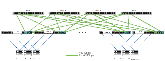
We have built a non-blocking network; however, congestion management algorithms should still be used to accommodate the best performance and ensure a lossless Ethernet fabric. Even in a non-blocking network, congesting is possible such as when two servers send at line rate to a single server. As discussed earlier in this document, both ECN and PFC should be used as congestion management tools.
The latency of the Cisco Nexus 93600CD-GX leaf switches, as well as the Cisco Nexus 9332D-GX2B spine switches, is 1.5 microseconds. You can connect very latency-sensitive machines to the same pair of leaf switches. The maximum end-to-end latency for this network fabric is ~4.5 microseconds for traffic that needs to traverse both leaf and spine switches to reach its destination. With congestion in most cases managed by WRED ECN, the latency provided by the RoCEv2 transport on the endpoints can be preserved.
The example network above can easily be expanded by adding more leaf switches. Also, the you can easily double the spine capacity by using Cisco Nexus 9364D-GX2A spine switches, which have 64 X 400G ports, or by adding more spine switches to keep a non-blocking fabric. Finally, you can use a three tier (super spine type) design to interconnect multiple non-blocking network fabrics.
In its simplest iteration, this network is dedicated to AI/ML workloads and is built with simple massively scalable data center (MSDC) network design principles in mind, running BGP as the control plane to the Layer 3 leaf switches. If this network must serve multiple tenants and functions, such as in many enterprise environments, you can leverage an MP-BGP EVPN VXLAN network. VXLAN networks allow network separation between tenants. The design principles described in this document work well with a simple Layer 3 or a VXLAN design.
For more information about MSDC designs and best practices, see the Cisco’s Massively Scalable Data Center Network Fabric White Paper.
Building a 400Gbps Back-End Network
For higher performance use cases, where GPU to GPU traffic requires 400Gbps Ethernet connectivity, it may be preferred to build a separate network for these communications. These types of networks are often referred to as a “back-end network.” Back-end networks generally are designed for GPUDirect (GPU to GPU) or GPUDirect Storage (GPU to storage) communications. The requirements for back-end networks are the same as any RoCEv2 network discussed in this document. The main difference for this type of network, assuming that it is connected at 400Gbps, is the recommended type of leaf and spine switches. To build a 400Gbps RoCEv2 network either the Cisco Nexus 9332D-GX2B or the Cisco Nexus 9364D-GX2A should be used as leaf switches. The Cisco Nexus 9364D-GX2A is the recommended spine switch. As with the network described earlier in this document a non-blocking fabric is required.
We will use the example of building a 512 GPU cluster. For this back-end network we will need to connect 512 400Gbps NICs. We will use the Cisco Nexus 9364D-GX2A as a leaf switch which will allow us to connect 32 GPUs/NICs to each leaf, leaving 32 ports for spine connectivity to build a non-blocking fabric. We will require 16 leaf switches to connect all 512 NICs.
To accommodate the amount of bandwidth coming from the leaf switches, 512 x 400Gbps ports are needed to the spines. We will use 8 Cisco Nexus 9364D-GX2A spine switches. Each leaf will connect to every spine using 4 x 400Gbps ports. The network is represented in the following diagram:
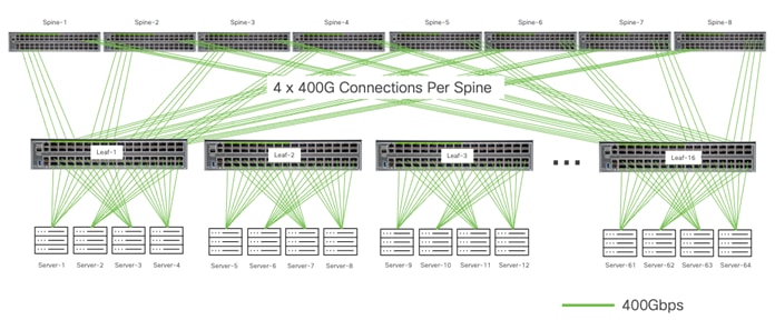
We chose a fixed form factor switch as a spine because the latency of the Cisco Nexus 9364D-GX2A switches is 1.5 microseconds. The maximum end-to-end latency for this network fabric is ~4.5 microseconds for traffic that needs to traverse both leaf and spine switches to reach its destination. With congestion managed by WRED ECN in most cases, the latency provided by the RoCEv2 transport on the endpoints can be preserved.
The same approach can be taken to build a 1024 GPU back-end network. The table below shows the requirements for 512 and 1024 GPU 400Gbps back-end networks.
| Total GPUs With 400Gbps Ethernet Connections |
Total Servers 8 GPUs per Server |
Total Nexus 9364D-GX2B Leaf Switches |
Total Nexus 9364D-GX2B Spine Switches |
Number of Connections From Each Leaf to Each Spine |
| 1024 |
128 |
32 |
16 |
2 |
| 512 |
64 |
16 |
8 |
4 |
Table 2. Connectivity requirements to build non-blocking fabrics.
Using Cisco Nexus Dashboard Fabric Controller to Automate Your AI/ML Network
Irrespective of the network architecture choice, MSDC or VXLAN, the Cisco Nexus Dashboard Fabric Controller (also known as the Fabric Controller service) can provide best practice configuration and automation capabilities, where the network is configured in a matter of minutes, including QoS configuration for PFC and ECN. The Fabric Controller service also provides automation to add new leaf or spine switches and make changes to access port configurations.
To learn more about the capabilities of the Fabric Controller service, see the Cisco Nexus Dashboard Fabric Controller 12 Data Sheet.
AI/ML clusters have stringent infrastructure requirements. The network plays an important function for making large AI/ML jobs complete more quickly and, if designed correctly, mitigate the risks of large AI/ML jobs failing due to high latency or packet drops.
AI/ML clusters can efficiently use Ethernet, and as such leverage it to provide low latency and high throughput of traffic using RoCEv2 as the transport. To build the lossless Ethernet network required for RoCEv2, congestion management tools should be used as discussed in this document. Along with the design described in this blueprint, it is important to use monitoring tools like Nexus Dashboard Insights to observe the network fabric’s behavior and tune it accordingly, so it provides the best possible performance.
The Cisco Nexus 9000 switches have the hardware and software capabilities available today to provide the right congestion management mechanisms, telemetry capabilities, ports speeds, and latency to build a modern high-performance AI/ML Network fabric.
● RoCE Storage Implementation over NX-OS VXLAN Fabrics
● Cisco Nexus Dashboard Insights for the Data Center Data Sheet
● Cisco Nexus Dashboard Fabric Controller 12 Data Sheet
| Americas Headquarters Cisco Systems, Inc. San Jose, CA |
Asia Pacific Headquarters Cisco Systems (USA) Pte. Ltd. Singapore |
Europe Headquarters Cisco Systems International BV Amsterdam The Netherlands |
Cisco has more than 200 offices worldwide. Address, phone numbers, and fax numbers are listed on the Cisco Website at https://www.cisco.com/go/offices.
Cisco and the Cisco logo are trademarks or registered trademarks of Cisco and/or its affiliates in the U.S. and other countries. To view a list of Cisco trademarks, go to this URL: https://www.cisco.com/go/trademarks. Third-party trademarks mentioned are the property of their respective owners. The use of the word partner does not imply a partnership relationship between Cisco and any other company. (1110R)