Installation Warnings and Guidelines
 Note |
Before you install, operate, or service a server, review the Regulatory Compliance and Safety Information for Cisco UCS C-Series Servers for important safety information. |
 Warning |
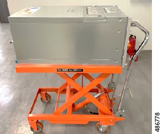
The fully configured server weighs approximately 265 lbs. (120 kg)! Never attempt to lift the server by yourself! Instead, use a lift, scissors jack, or some other device to lift and bear the weight of the server while you are installing or servicing it. If you must lift or handle the server without mechanical assistance, use two or more people to lift and handle server. Always use safe lifting practices when lifting or moving the server. |
 Caution |
When connecting the chassis to facility power, make sure not to overload the capacity of a PDU or power strip. For example, do not connect all PSUs to one PDU or power strip that is not capable of carrying the total power draw of the chassis. |
Caution |
To ensure proper airflow, it is necessary to rack the servers using rail kits. Physically placing the units on top of one another (“stacking”) without the use of the rail kits blocks the air vents on top of the servers, which could result in overheating, higher fan speeds, and higher power consumption. We recommend that you mount your servers on rail kits when you are installing them into the rack because these rails provide the minimal spacing required between the servers. No additional spacing between the servers is required when you mount the units using rail kits. |
Caution |
Avoid uninterruptible power supply (UPS) types that use ferroresonant technology. These UPS types can become unstable with systems such as the Cisco UCS, which can have substantial current draw fluctuations from fluctuating data traffic patterns. |
When you are installing a server, use the following guidelines:
-
Plan your site configuration and prepare the site before installing the server. See the Cisco UCS Site Preparation Guide for the recommended site planning tasks.
-
Ensure that there is adequate space around the server to allow for accessing the server and for adequate airflow. The airflow in this server is from front to back.
-
Ensure that the site air-conditioning meets the thermal requirements listed in the Environmental Specifications.
-
Ensure that the site power meets the power requirements listed in the Power Specifications. If available, you can use an uninterruptible power supply (UPS) to protect against power failures.
-
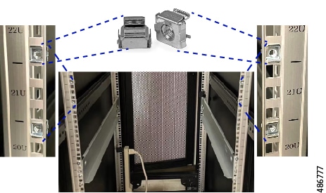
Before attempting rack installation of the server, you will find it helpful to note important information, such as the server's MAC address and serial number. This information is on a label at the top right corner of the server. Figure 1. Location of MAC Address Label 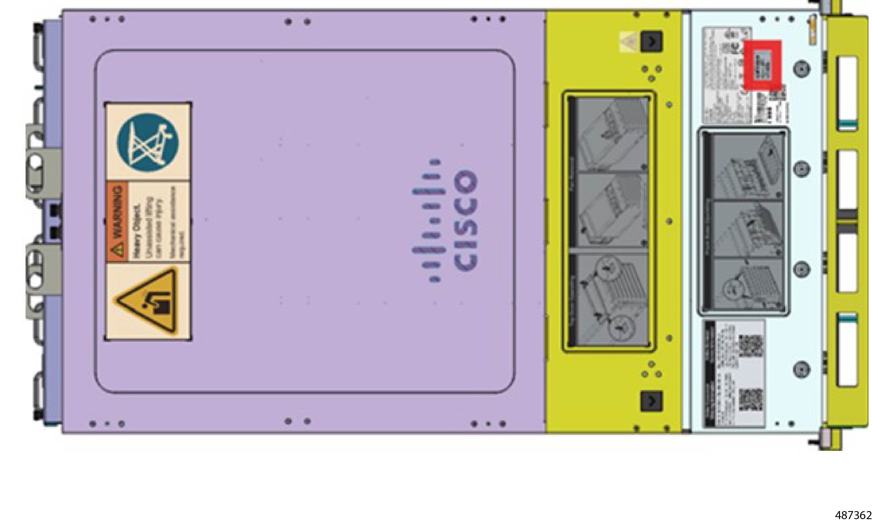
Statement 1005—Circuit Breaker
Warning |
This product relies on the building’s installation for short-circuit (overcurrent) protection. To reduce risk of electric shock or fire, ensure that the protective device is rated not greater than: 240V, 16 A. |
Statement 1071—Warning Definition
Warning |
IMPORTANT SAFETY INSTRUCTIONS Before you work on any equipment, be aware of the hazards involved with electrical circuitry and be familiar with standard practices for preventing accidents. Read the installation instructions before using, installing, or connecting the system to the power source. Use the statement number at the beginning of each warning statement to locate its translation in the translated safety warnings for this device. SAVE THESE INSTRUCTIONS  |
Statement 1074—Comply with Local and National Electrical Codes
Warning |
To reduce risk of electric shock or fire, installation of the equipment must comply with local and national electrical codes. |
Statement 1017—Restricted Area
Warning |
This unit is intended for installation in restricted access areas. Only skilled, instructed, or qualified personnel can access a restricted access area. |
 Feedback