Overview
The Cisco UCS C885A M8 Rack Server is a dense-GPU server designed to deliver massive, scalable accelerated compute capabilities to address the most demanding AI workloads, including deep learning/Large Language Model (LLM) training, model fine-tuning, large model inferencing, and Retrieval-Augmented Generation (RAG).
To deliver massive accelerated compute performance in a single server, each server supports a maximum of eight GPUs of the following types:
-
NVIDIA® H100 Tensor Core or NVIDIA® H200 Tensor Core Server PCI Express Module (SXM) GPUs. SXM is a socket-based GPU interconnect method used by NVIDIA GPUs.
-
AMD Instinct™ MI300X and AMD Instinct™ MI350X OCP Accelerator Model (OAM) GPUs. OAM is an Open Compute GPU interconnect standard that avoids GPU vendor lock in.
For north-south traffic, the server supports up to two NVIDIA BlueField-3 B3220 DPUs or up to two NVIDIA ConnectX-7 NICs.
For east-west traffic, the server supports up to eight NVIDIA ConnectX-7s, AMD Pensando™ Pollara 400 AI NICs, or BlueField-3 B3140H SuperNICs for GPUs enabling AI model training across a cluster of dense-GPU servers.
The server is offered in fixed configurations with resources optimized for intensive AI and HPC workloads.
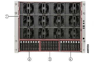
Server Front and Rear Views
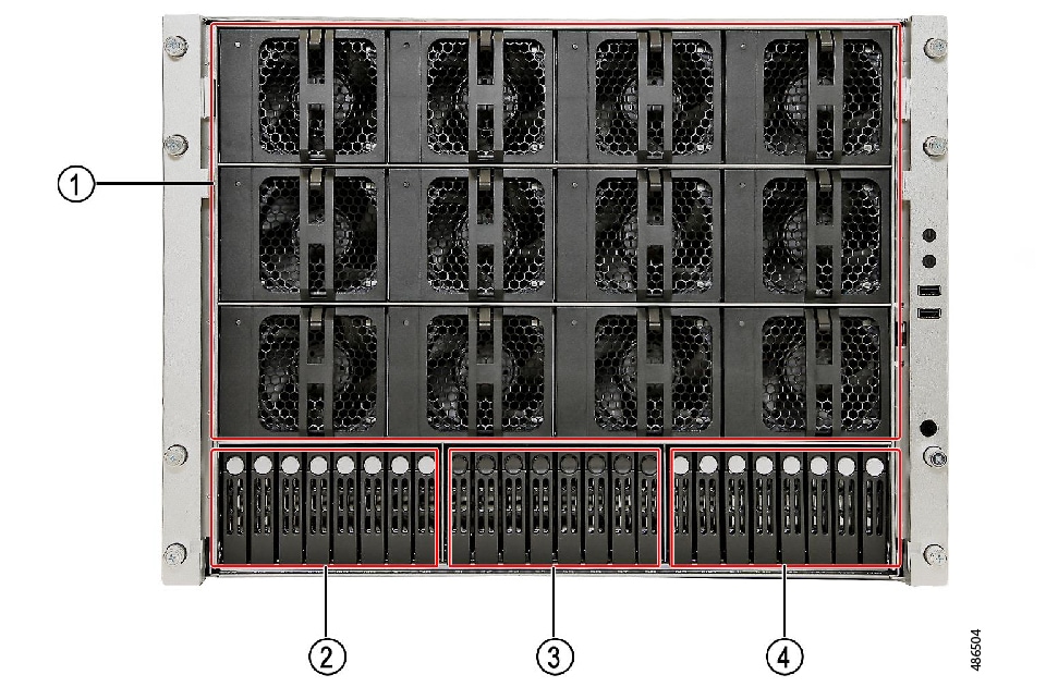
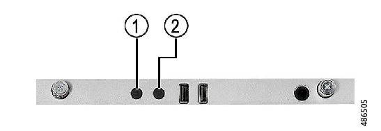
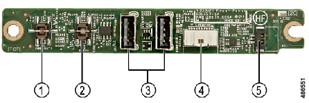
The front of the server contains fans, storage modules, system LEDs, and USB port access covered by a bezel.
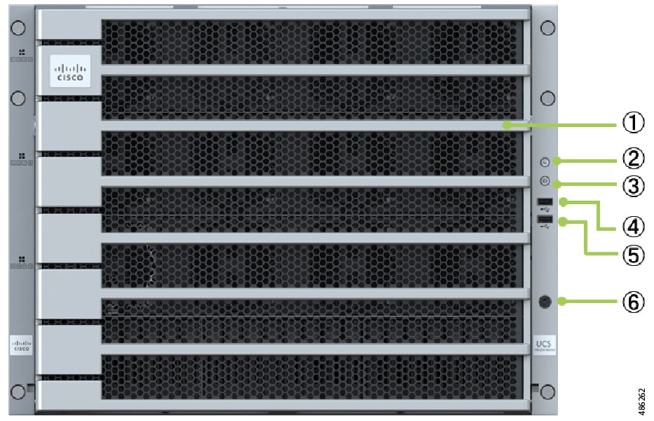
|
Item |
Description |
|---|---|
|
1 |
Front Bezel |
|
2 |
Power Button with Power/Fault LED |
|
3 |
Unit ID (UID) Button with integrated LED |
|
4 |
USB 2.0 port |
|
5 |
USB 2.0 port |
|
6 |
Thermal Sensor |
Slot Numbering, Server Front
Slot numbers are silk screened onto the front chassis. You can use the silkscreening on the chassis to locate appropriate slots.
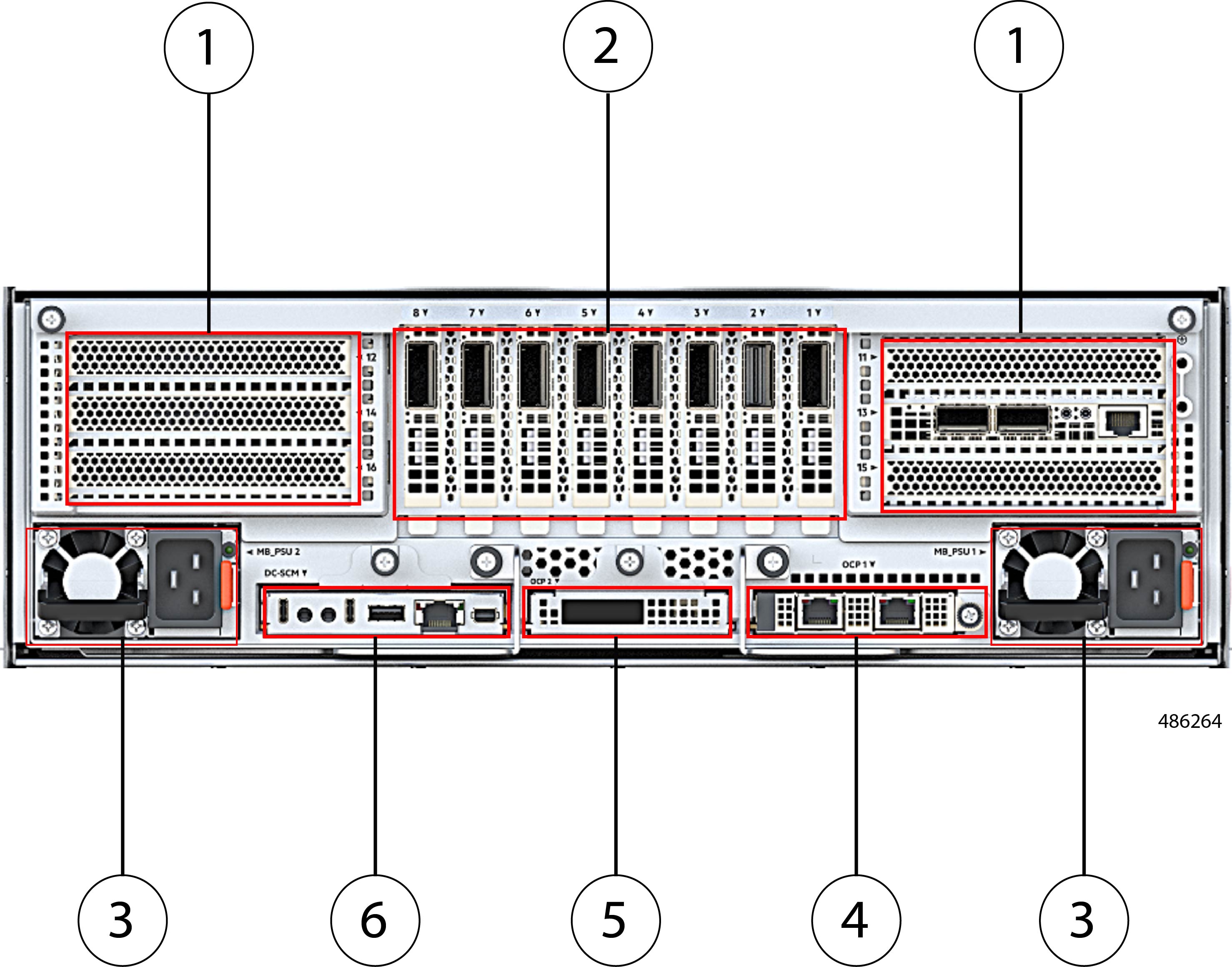
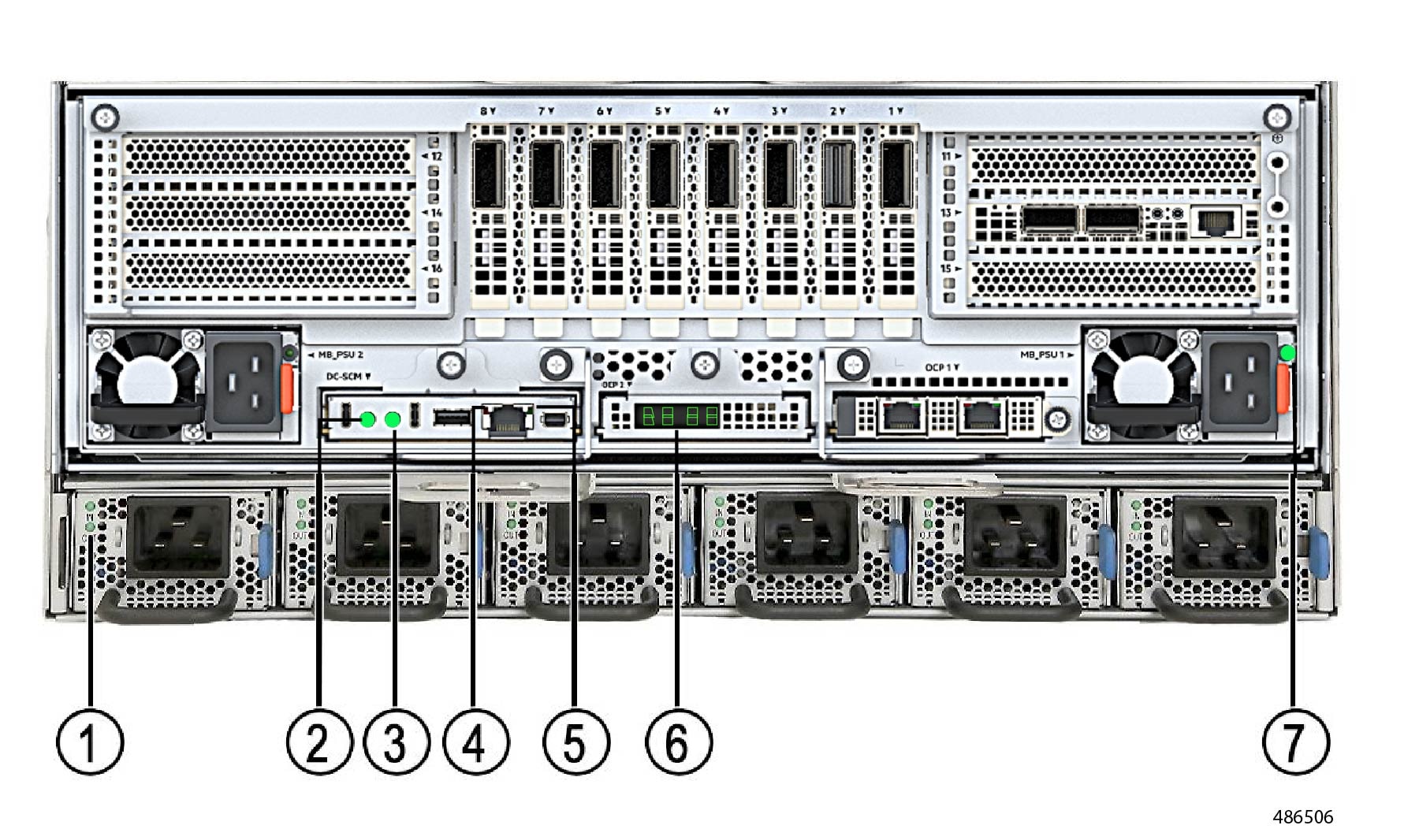
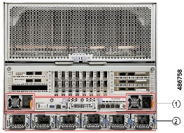
Server Rear View
The rear of the server contains compute and networking, as well as power supplies and management ports.
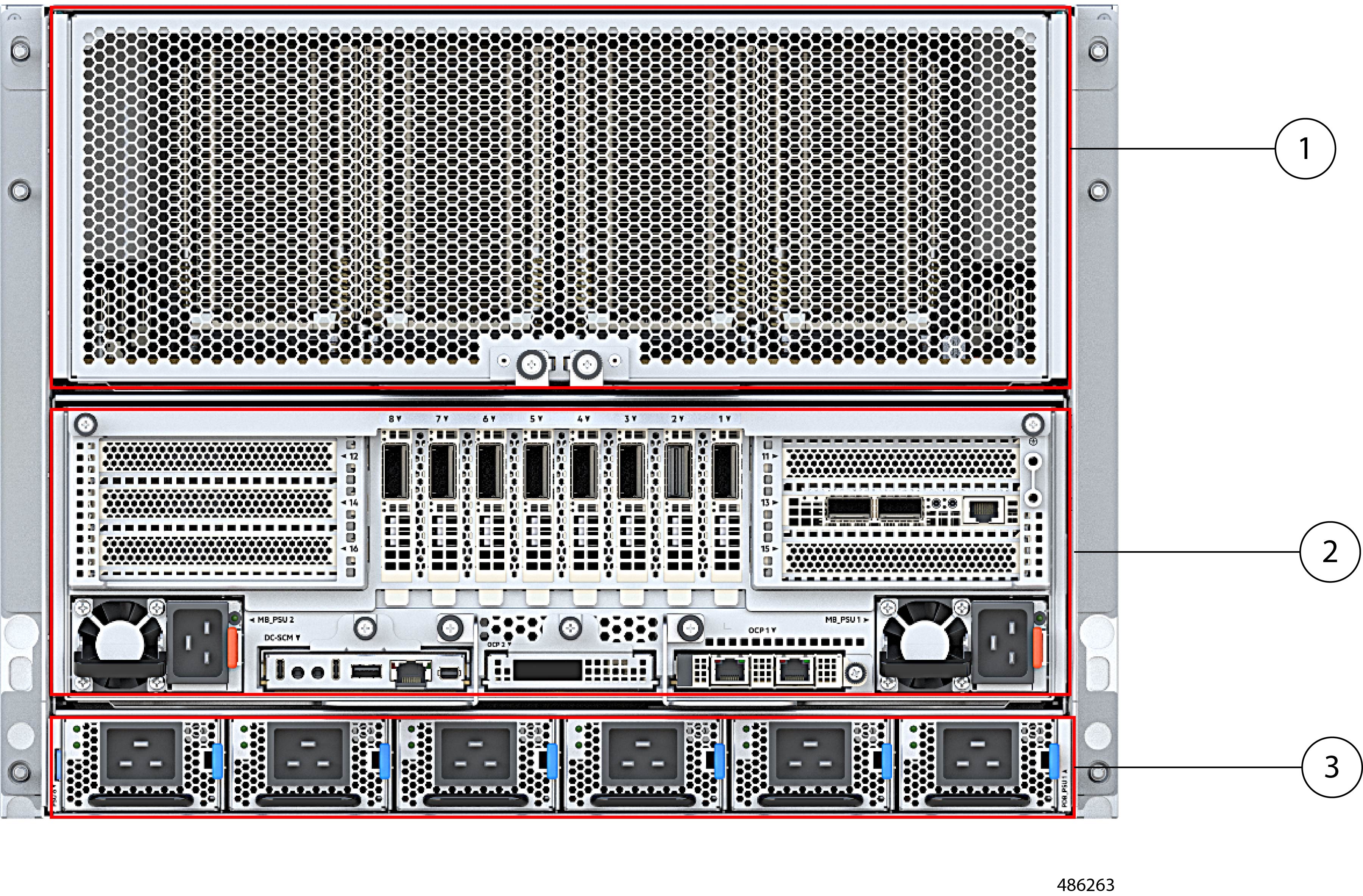
|
Item |
Description |
|---|---|
|
1 |
HGBB Tray |
|
2 |
CPU Tray |
|
3 |
Redundant Power Supply Units |
Slot Numbering, Server Rear View
Slot numbers are silk screened onto the rear of the chassis. You can use the silkscreening on the chassis to locate appropriate slots.
Server Configurations
Cisco UCS C885A M8 Rack Server is shipped with a few components pre-configured/auto included, but for a few components, you will need toselect an option.
|
PID |
Description |
||
|---|---|---|---|
|
Cisco UCSC H100
|
|||
|
UCSC-885A-M8-H11 |
UCS C885A M8 Rack - H100 GPU, eight ConnectX-7 400GbE, one B3220, 2.3TB Memory |
||
|
UCSC-885A-M8-H12 |
UCS C885A M8 Rack - H100 GPU, 8x B3140H, 1x B3220, 2.3TB Memory |
||
|
UCSC-885A-M8-H13 |
UCS C885A M8 Rack - H100 GPU, eight ConnectX-7 400GbE, two ConnectX-7 2x200GbE, 1.5TB Memory |
||
|
Cisco UCSC H200 |
|||
|
UCSC-885A-M8-H20 |
UCS C885A M8 Rack - H200 GPU, E-W NICs: none, two ConnectX-7 2x200 GbE, 1.5TB Memory |
||
|
UCSC-885A-M8-H21 |
UCS C885A M8 Rack - H200 GPU, eight ConnectX-7, one B3220, 2.3TB Memory |
||
|
UCSC-885A-M8-H22 |
UCS C885A M8 Rack - H200 GPU, 8x B3140H, 1x B3220, 2.3TB Memory |
||
|
UCSC-885A-M8-H23 |
UCS C885A M8 Rack - H200 GPU, eight ConnectX-7 400GbE, two ConnectX-7 2x200 GbE, 2.3TB Memory |
||
|
UCSC-885A-M8-H24 |
UCS C885A M8 Rack - H200 GPU, eight NVIDIA B3140H, 1x B3220, 2.3TB Memory |
||
|
UCSC-885A-M8-H25 |
UCS C885A M8 Rack - H200 GPU, eight ConnectX-7 400GbE, two ConnectX-7 2x200 GbE, 3TB Memory |
||
|
UCSC-885A-M8-H26 |
UCS C885A M8 Rack - H200 GPU, eight ConnectX-7 400GbE, two B32420, 2.3TB Memory |
||
|
UCSC-885A-M8-H27 |
UCS C885A M8 Rack - H200 GPU, eight ConnectX-7, 2x B3220, 3TB Mem |
||
|
UCSC-885A-M8-H28 |
UCS C885A M8 Rack - H200 GPU, 8x B3140H, 2x B3220, 2.3TB Memory |
||
|
Cisco UCSC MI300X |
|||
|
UCSC-885A-M8-M3X0 |
UCS C885A M8 Rack - MI300X GPU, E-W NICs: None, two ConnectX-7 2x200 GbE, 1.5TB Memory |
||
|
UCSC-885A-M8-M3X1 |
UCS C885A M8 Rack - MI300X GPU, eight ConnectX-7, one B3220, 2.3TB Memory |
||
|
UCSC-885A-M8-M3X2 |
UCS C885A M8 Rack - MI300X GPU, 8x B3140H, 1x B3220, 2.3TB Memory |
||
|
UCSC-885A-M8-M3X3 |
UCS C885A M8 Rack - MI300X GPU, eight ConnectX-7 400 GbE, two ConnectX-7 2x200 GbE, 2.3TB Memory |
||
|
UCSC-885A-M8-M3X4 |
UCS C885A M8 Rack - MI300X GPU, ten ConnectX-7, 3TB Mem |
||
|
UCSC-885A-M8-M3X5 |
UCS C885A M8 Rack - MI300X GPU, eight ConnectX-7 400 GbE, 2x B3220, 2.3TB Memory |
||
|
UCSC-885A-M8-M3X6 |
UCS C885A M8 Rack - MI300X GPU, twelve ConnectX-7, 2.3TB Mem |
||
|
Cisco UCS MI350X |
|||
|
UCSC-885A-M8-M352 |
UCS C885A M8 Rack - MI350X AMD UBB , eight AMD Pensando™ Pollara 400 AI NICs, two ConnectX-7 2x 200 GbE NICs, 2.3TB Mem |
||
|
UCSC-885A-M8-M353 |
UCS C885A M8 Rack - MI350X AMD UBB, eight ConnectX-7 1x400 GbE NICs, two ConnectX-7 2x200 GbE NICs, 2.3TB Mem |
||
|
UCSC-885A-M8-M354 |
UCS C885A M8 Rack - MI350X AMD UBB, eight AMD Pensando™ Pollara 400 AI NICs, two ConnectX-7 2x200 GbE NICs, 3TB Mem |
||
|
UCSC-885A-M8-M355 |
UCS C885A M8 Rack - MI350X AMD UBB, eight ConnectX-7 1x400 GbE NICs, two ConnectX-7 2x200 GbE NICs, 3TB Mem |
||
|
UCSC-885A-M8-M356 |
UCS C885A M8 Rack - MI350X AMD UBB, eight ConnectX-7 1x400 GbE NICs, two ConnectX-7 2x200 GbE NICs plus two ConnectX-7 4x25 GbE NICs, 3TB Mem |
||
Each UCSC-885A-M8-H11 server supports the following:
|
Product ID (PID) |
PID Description |
QTY Included |
||
|---|---|---|---|---|
|
Drive |
||||
|
C885A-NV-C1T9KV |
UCS C885A M8 SSD 1.92TB NVMe |
16 |
||
|
GPU |
||||
|
C885A-M8-H1SX-SLD |
UCS C885A M8 H100 UBB GPU Sled (8 GPUs)
|
1 |
||
|
CPU |
||||
|
C885A-M8-CC-SLD01 |
UCS C885A M8 CPU Sled containing two AMD 9554 GPUs ad 24 96GB 5600 DDR5 DIMMs |
1 |
||
|
PCIe Card |
||||
|
C885A-O-ID10GC |
UCS C885A M8 OCP INTEL X710 T2L |
1 |
||
|
North-South NIC: NVIDIA BlueField-3 B3220 Super NIC |
1 |
|||
|
East-West NIC: NVIDIA ConnenctX-7 Network Adapters |
8 |
|||
|
Power Option |
||||
|
C885A-PSU-3000W |
UCS C885A M8 3000W 54V AC Power Supply |
6 |
||
|
C885A-PSU-2700W |
UCS C885A M8 PSU 2700W 12V AC/DC TITANIUM Power Cord |
2 |
||
|
SCM Card |
||||
|
C885A-M8-DCSCMGN |
UCS C885A M8 DC-SCM Card, AMD |
1 |
||
|
BZL |
||||
|
C885A-HCI-BZL |
UCS C885A M8 Bezel |
1 |
||
|
Chassis |
||||
|
C885A-M8-CHASSIS |
UCS C885A M8 Chassis |
1 |
||
Each UCSC-885A-M8-H12 server supports the following:
|
Product ID (PID) |
PID Description |
QTY Included |
||
|---|---|---|---|---|
|
Drive |
||||
|
C885A-NV-C1T9KV |
UCS C885A M8 SSD 1.92TB NVMe |
16 |
||
|
GPU |
||||
|
C885A-M8-H1SX-SLD |
UCS C885A M8 H100 UBB GPU Sled (8 GPUs)
|
1 |
||
|
CPU |
||||
|
C885A-M8-CC-SLD02 |
UCS C885A M8 CPU Sled containing two AMD 9575F CPUs and 24 96GB 6400 DDR5 DIMMs |
1 |
||
|
PCIe Card |
||||
|
C885A-O-ID10GC |
UCS C885A M8 OCP INTEL X710 T2L |
1 |
||
|
North-South NIC: NVIDIA BlueField-3 B3220 Super NIC |
1 |
|||
|
East-West NIC: NVIDIA BlueField-3 B3140H SuperNICs |
8 |
|||
|
Power Option |
||||
|
C885A-PSU-3000W |
UCS C885A M8 3000W 54V AC Power Supply |
6 |
||
|
C885A-PSU-2700W |
UCS C885A M8 PSU 2700W 12V AC/DC TITANIUM Power Cord |
2 |
||
|
SCM Card |
||||
|
C885A-M8-DCSCM |
UCS C885A M8 DC-SCM Card, AMD |
1 |
||
|
BZL |
||||
|
C885A-HCI-BZL |
UCS C885A M8 Bezel |
1 |
||
|
Chassis |
||||
|
C885A-M8-CHASSIS |
UCS C885A M8 Chassis |
1 |
||
Each UCSC-885A-M8-H13 server supports the following:
|
Product ID (PID) |
PID Description |
QTY Included |
||
|---|---|---|---|---|
|
Drive |
||||
|
C885A-NV-C1T9KV |
UCS C885A M8 SSD 1.92TB NVMe |
2 |
||
|
GPU |
||||
|
C885A-M8-H1SX-SLD |
UCS C885A H100 UBB GPU Sled (8 GPUs)
|
1 |
||
|
CPU |
||||
|
C885A-M8-CC-SLD09 |
UCS C885A M8 CPU Sled containing two AMD 9554 CPUs and 24 64GB 5600 DDR5 |
1 |
||
|
PCIe Card |
||||
|
C885A-O-ID10GC |
UCS C885A M8 OCP INTEL X710 T2L |
1 |
||
|
North-South NIC: NVIDIA ConnectX-7 Dual-Port 200 GbE Network Adapters |
2 |
|||
|
East-West NIC: NVIDIA ConnectX-7 400 GbE Network Adapters. |
8 |
|||
|
Power Option |
||||
|
C885A-PSU-3000W |
UCS C885A M8 3000W 54V AC Power Supply |
6 |
||
|
C885A-PSU-2700W |
UCS C885A M8 PSU 2700W 12V AC/DC TITANIUM Power Cord |
2 |
||
|
SCM Card |
||||
|
C885A-M8-DCSCMGN |
UCS C885A M8 DC-SCM Card, AMD |
1 |
||
|
BZL |
||||
|
C885A-HCI-BZL |
UCS C885A M8 Bezel |
1 |
||
|
Chassis |
||||
|
C885A-M8-CHASSIS |
UCS C885A M8 Chassis |
1 |
||
Each UCSC-885A-M8-H20 server supports the following:
|
Product ID (PID) |
PID Description |
QTY Included |
|---|---|---|
|
Drive |
||
|
C885A-NV-C1T9KV |
UCS C885A M8 SSD 1.92TB NVMe |
2 |
|
GPU |
||
|
C885A-M8-H2SX-SLD |
UCS C885A M8 H200 GPU UBB Sled containing 8 GPUs |
1 |
|
CPU |
||
|
C885A-M8-CC-SLD06 |
UCS C885A M8 CPU Sled containing two AMD 9535 CPUs with 24 64GB 6400 DDR5 DIMMs |
1 |
|
PCIe Card |
||
|
C885A-O-ID10GC |
UCS C885A M8 OCP INTEL X710 T2L |
1 |
|
North-South NICs: NVIDIA ConnectX-7 Dual-Port 200 GbE Network Adapters |
2 |
|
|
East-West NIC: None |
0 |
|
|
Power Option |
||
|
C885A-PSU-3000W |
UCS C885A M8 3000W 54V AC Power Supply |
6 |
|
C885A-PSU-2700W |
UCS C885A M8 PSU 2700W 12V AC/DC TITANIUM Power Cord |
2 |
|
SCM Card |
||
|
C885A-M8-DCSCM |
UCS C885A M8 DC-SCM Card, AMD |
1 |
|
BZL |
||
|
C885A-HCI-BZL |
UCS C885A M8 Bezel |
1 |
|
Chassis |
||
|
C885A-M8-CHASSIS |
UCS C885A M8 Chassis |
1 |
Each UCSC-885A-M8-H21 server supports the following:
|
Product ID (PID) |
PID Description |
QTY Included |
|---|---|---|
|
Drive |
||
|
C885A-NV-C1T9KV |
UCS C885A M8 SSD 1.92TB NVMe |
16 |
|
GPU |
||
|
C885A-M8-H2SX-SLD |
UCS C885A H200 UBB GPU Sled containing 8 H200 GPUs |
1 |
|
CPU |
||
|
C885A-M8-CC-SLD01 |
UCS C885A M8 CPU Sled containing two AMD 9554 CPUs with 24 96GB 5600 DDR5 DIMMs |
1 |
|
PCIe Card |
||
|
C885A-O-ID10GC |
UCS C885A M8 OCP Intel X710 T2L |
1 |
|
North-South NICs: NVIDIA BlueField-3 B3220 SuperNIC |
1 |
|
|
East-West NICs: NVIDIA ConnectX-7 Single-Port 400 GbE NIC |
8 |
|
|
Power Option |
||
|
C885A-PSU-3000W |
UCS C885A M8 3000W 54V AC Power Supply |
6 |
|
C885A-PSU-2700W |
UCS C885A M8 PSU 2700W 12V AC/DC TITANIUM Power Cord |
2 |
|
SCM Card |
||
|
C885A-M8-DCSCMGN |
UCS C885A M8 DC-SCM Card, AMD |
1 |
|
BZL |
||
|
C885A-HCI-BZL |
UCS C885A M8 Bezel |
1 |
|
Chassis |
||
|
C885A-M8-CHASSIS |
UCS C885A M8 Chassis |
1 |
Each UCSC-885A-M8-H22 server supports the following:
|
Product ID (PID) |
PID Description |
QTY Included |
|---|---|---|
|
Drive |
||
|
C885A-NV-C1T9KV |
UCS C885A M8 SSD 1.92TB NVMe |
16 |
|
GPU |
||
|
C885A-M8-H2SX-SLD |
UCS C885A H200 UBB GPU Sled (8 GPUs) |
1 |
|
CPU |
||
|
C885A-M8-CC-SLD02 |
UCS C885A M8 CPU Sled containing two AMD 9575F CPUs and 24 96GB 6400 DDR5 DIMMs |
1 |
|
PCIe Card |
||
|
C885A-O-ID10GC |
UCS C885A M8 OCP INTEL X710 T2L |
1 |
|
North-South NICs: NVIDIA BlueField-3 B3220 SuperNIC |
1 |
|
|
East-West NICs: NVIDIA BlueField-3 B3140H SuperNICs |
8 |
|
|
Power Option |
||
|
C885A-PSU-3000W |
UCS C885A M8 3000W 54V AC Power Supply |
6 |
|
C885A-PSU-2700W |
UCS C885A M8 PSU 2700W 12V AC/DC TITANIUM Power Cord |
2 |
|
SCM Card |
||
|
C885A-M8-DCSCM |
UCS C885A M8 DC-SCM Card, AMD |
1 |
|
BZL |
||
|
C885A-HCI-BZL |
UCS C885A M8 Bezel |
1 |
|
Chassis |
||
|
C885A-M8-CHASSIS |
UCS C885A M8 Chassis |
1 |
Each UCSC-885A-M8-H23 server supports the following:
|
Product ID (PID) |
PID Description |
QTY Included |
|---|---|---|
|
Drive |
||
|
C885A-NV-C1T9KV |
UCS C885A M8 SSD 1.92TB NVMe |
2 |
|
GPU |
||
|
C885A-M8-H2SX-SLD |
UCS C885A H200 UBB Sled (8 GPUs |
1 |
|
CPU |
||
|
C885A-M8-CC-SLD07 |
UCS C885A M8 CPU Sled containing two AMD 9575F CPU and 24 96GB 6400 DDR5 DIMMs |
1 |
|
PCIe Card |
||
|
C885A-O-ID10GC |
UCS C885A M8 OCP INTEL X710 T2L |
1 |
|
North-South NIC: NVIDIA ConnectX-7 Dual-Port 200 GbE Network Adapter |
2 |
|
|
East-West NIC: NVIDIA ConnectX-7 Single-Port 400 GbE, Network Adapter |
8 |
|
|
Power Option |
||
|
C885A-PSU-3000W |
UCS C885A M8 3000W 54V AC Power Supply |
6 |
|
C885A-PSU-2700W |
UCS C885A M8 PSU 2700W 12V AC/DC TITANIUM Power Cord |
2 |
|
SCM Card |
||
|
C885A-M8-DCSCM |
UCS C885A M8 DC-SCM Card, AMD |
1 |
|
BZL |
||
|
C885A-HCI-BZL |
UCS C885A M8 Bezel |
1 |
|
Chassis |
||
|
C885A-M8-CHASSIS |
UCS C885A M8 Chassis |
1 |
Each UCSC-885A-M8-H24 server supports the following:
|
Product ID (PID) |
PID Description |
QTY Included |
|---|---|---|
|
Drive |
||
|
C885A-NV-C1T9KV |
UCS C885A M8 SSD 1.92TB NVMe |
2 |
|
GPU |
||
|
C885A-M8-H2SX-SLD |
UCS C885A H200 UBB GPU Sled (8 GPUs) |
1 |
|
CPU |
||
|
C885A-M8-CC-SLD19 |
UCS C885A M8 CPU Sled consisting of two AMD 9575F CPUS with 24 96GB 6400 DDR5 DIMMs |
1 |
|
PCIe Card |
||
|
C885A-O-ID10GC |
UCS C885A M8 OCP INTEL X710 T2L |
1 |
|
North-South NIC: NVIDIA BlueField-3 B3220 SuperNIC |
1 |
|
|
East-West NIC: NVIDIA BlueField-3 B3140 SuperNIC |
8 |
|
|
Power Option |
||
|
C885A-PSU-3000W |
UCS C885A M8 3000W 54V AC Power Supply |
6 |
|
C885A-PSU-2700W |
UCS C885A M8 PSU 2700W 12V AC/DC TITANIUM Power Cord |
2 |
|
SCM Card |
||
|
C885A-M8-DCSCM |
UCS C885A M8 DC-SCM Card, AMD |
1 |
|
BZL |
||
|
C885A-HCI-BZL |
UCS C885A M8 Bezel |
1 |
|
Chassis |
||
|
C885A-M8-CHASSIS |
UCS C885A M8 Chassis |
1 |
Each UCSC-885A-M8-H25 server supports the following:
|
Product ID (PID) |
PID Description |
QTY Included |
|---|---|---|
|
Drive |
||
|
C885A-NV-C1T9KV |
UCS C885A M8 SSD 1.92TB NVMe |
2 |
|
GPU |
||
|
C885A-M8-H2SX-SLD |
UCS C885A M8 H200 UBB GPU Sled (8 GPUs) |
1 |
|
CPU |
||
|
C885A-M8-CC-SLD12 |
UCS C885A M8 CPU Sled containing two AMD 9575F CPUs and 24 128GB 6400 DDR5 DIMMs |
1 |
|
PCIe Card |
||
|
C885A-O-ID10GC |
UCS C885A M8 OCP Intel X710 T2L |
1 |
|
North-South NICs: NVIDIA ConnectX-7 Dual-Port 200 GbE Network Adapter |
2 |
|
|
East-West NICs: NVIDIA ConnectX-7 Single-Port 400 GbE network Adapter |
8 |
|
|
Power Option |
||
|
C885A-PSU-3000W |
UCS C885A M8 3000W 54V AC Power Supply |
6 |
|
C885A-PSU-2700W |
UCS C885A M8 PSU 2700W 12V AC/DC TITANIUM Power Cord |
2 |
|
SCM Card |
||
|
C885A-M8-DCSCM |
UCS C885A M8 DC-SCM Card, AMD |
1 |
|
BZL |
||
|
C885A-HCI-BZL |
UCS C885A M8 Bezel |
1 |
|
Chassis |
||
|
C885A-M8-CHASSIS |
UCS C885A M8 Chassis |
1 |
Each UCSC-885A-M8-H26 server supports the following:
|
Product ID (PID) |
PID Description |
QTY Included |
|---|---|---|
|
Drive |
||
|
C885A-NV-C1T9KV |
UCS C885A M8 SSD 1.92TB NVMe |
2 |
|
GPU |
||
|
C885A-M8-H2SX-SLD |
UCS C885A M8 H200 UBB GPU Sled (8 GPUs) |
1 |
|
CPU |
||
|
C885A-M8-CC-SLD08 |
UCS C885A M8 CPU Sled containing two AMD 9575F CPUs and 24 96GB 6400 DDR5 DIMMs |
1 |
|
PCIe Card |
||
|
C885A-O-ID10GC |
UCS C885A M8 OCP Intel X710 T2L |
1 |
|
North-South NIC: NVIDIA BlueField-3 B3220 SuperNIC |
2 |
|
|
East-West NIC: NVIDIA Single-Port 400 GbE ConnectX-7 NIC |
8 |
|
|
Power Option |
||
|
C885A-PSU-3000W |
UCS C885A M8 3000W 54V AC Power Supply |
6 |
|
C885A-PSU-2700W |
UCS C885A M8 PSU 2700W 12V AC/DC TITANIUM Power Cord |
2 |
|
SCM Card |
||
|
C885A-M8-DCSCM |
UCS C885A M8 DC-SCM Card, AMD |
1 |
|
BZL |
||
|
C885A-HCI-BZL |
UCS C885A M8 Bezel |
1 |
|
Chassis |
||
|
C885A-M8-CHASSIS |
UCS C885A M8 Chassis |
1 |
Each UCSC-885A-M8-H27 server supports the following:
|
Product ID (PID) |
PID Description |
QTY Included |
|---|---|---|
|
Drive |
||
|
C885A-NV-C1T9KV |
UCS C885A M8 SSD 1.92TB NVMe |
2 |
|
GPU |
||
|
C885A-M8-H2SX-SLD |
UCS C885A M8 H200 UBB GPU Sled (8 GPUs) |
1 |
|
CPU |
||
|
C885A-M8-CC-SLD23 |
UCS C885A M8 CPU Sled AMD 9535 CPUs with 24 128GB 6400 DDR5 DIMMs |
1 |
|
PCIe Card |
||
|
C885A-O-ID10GC |
UCS C885A M8 OCP Intel X710 T2L |
1 |
|
North-South NIC: NVIDIA BlueField-3 B3220 SuperNIC |
2 |
|
|
East-West NICs: NVIDIA ConnectX-7 Single-port 400 GbE Network Adapter |
8 |
|
|
Power Option |
||
|
C885A-PSU-3000W |
UCS C885A M8 3000W 54V AC Power Supply |
6 |
|
C885A-PSU-2700W |
UCS C885A M8 PSU 2700W 12V AC/DC TITANIUM Power Cord |
2 |
|
SCM Card |
||
|
C885A-M8-DCSCM |
UCS C885A M8 DC-SCM Card NVIDIA GPU, 5th Gen AMD EPYC CPU |
1 |
|
BZL |
||
|
C885A-HCI-BZL |
UCS C885A M8 Bezel |
1 |
|
Chassis |
||
|
C885A-M8-CHASSIS |
UCS C885A M8 Chassis |
1 |
Each UCSC-885A-M8-H28 server supports the following:
|
Product ID (PID) |
PID Description |
QTY Included |
|---|---|---|
|
Drive |
||
|
C885A-NV-C1T9KV |
UCS C885A M8 SSD 1.92TB NVMe |
2 |
|
GPU |
||
|
C885A-M8-H2SX-SLD |
UCS C885A M8 H200 UBB GPU Sled (8 GPUs) |
1 |
|
CPU |
||
|
C885A-M8-CC-SLD11 |
UCS C885A M8 CPU Sled containing two AMD 9575F CPUs and 24 96GB 6400 DDR5 DIMMs |
1 |
|
PCIe Card |
||
|
C885A-O-ID10GC |
UCS C885A M8 OCP Intel X710 T2L |
1 |
|
North-South NIC: NVIDIA BlueField-3 B3220 SuperNIC |
2 |
|
|
East-West NIC: NVIDIA BlueField-3 B3140 SuperNIC |
8 |
|
|
Power Option |
||
|
C885A-PSU-3000W |
UCS C885A M8 3000W 54V AC Power Supply |
6 |
|
C885A-PSU-2700W |
UCS C885A M8 PSU 2700W 12V AC/DC TITANIUM Power Cord |
2 |
|
SCM Card |
||
|
C885A-M8-DCSCMAA |
UCS C885A M8 DC-SCM Card, AMD |
1 |
|
BZL |
||
|
C885A-HCI-BZL |
UCS C885A M8 Bezel |
1 |
|
Chassis |
||
|
C885A-M8-CHASSIS |
UCS C885A M8 Chassis |
1 |
Each UCSC-885A-M8-M3X0 server supports the following:
|
Product ID (PID) |
PID Description |
QTY Included |
|---|---|---|
|
Drive |
||
|
C885A-NV-C1T9KV |
UCS C885A M8 SSD 1.92TB NVMe |
2 |
|
GPU |
||
|
C885A-M8-M13X-SLD |
UCS C885A MI300X GPU SLED MI300X |
1 |
|
CPU |
||
|
C885A-M8-CC-SLD14 |
UCS C885A M8 CPU Sled containing two AMD 9535F CPUs and 24 64GB 6400 DDR5 DIMMs |
1 |
|
PCIe Card |
||
|
C885A-O-ID10GC |
UCS C885A M8 OCP Intel X710 T2L |
1 |
|
North-South NIC: NVIDIA ConnectX-7 Network Adapters |
2 |
|
|
East-West NIC: None |
0 |
|
|
Power Option |
||
|
C885A-PSU-3000W |
UCS C885A M8 3000W 54V AC Power Supply |
6 |
|
C885A-PSU-2700W |
UCS C885A M8 PSU 2700W 12V AC/DC TITANIUM Power Cord |
2 |
|
SCM Card |
||
|
C885A-M8-DCSCMAA |
UCS C885A M8 DC-SCM Card, AMD |
1 |
|
BZL |
||
|
C885A-HCI-BZL |
UCS C885A M8 Bezel |
1 |
|
Chassis |
||
|
C885A-M8-CHASSIS |
UCS C885A M8 Chassis |
1 |
Each UCSC-885A-M8-M3X1 server supports the following:
|
Product ID (PID) |
PID Description |
QTY Included |
|---|---|---|
|
Drive |
||
|
C885A-NV-C1T9KV |
UCS C885A M8 SSD 1.92TB NVMe |
16 |
|
GPU |
||
|
C885A-M8-M13X-SLD |
UCS C885A MI300X GPU SLED (8 GPUs) |
1 |
|
CPU |
||
|
C885A-M8-CC-SLD03 |
UCS C885A M8 CPU SLED AMD 9575F 96GB 6400 DDR5 ConnectX-7 B3220 |
1 |
|
PCIe Card |
||
|
C885A-O-ID10GC |
UCS C885A M8 OCP Intel X710 T2L |
1 |
|
North-South NIC: NVIDIA BlueField-3 B3220 SuperNIC |
1 |
|
|
East-West NIC: NVIDIA ConnectX-7 Network Adapters |
8 |
|
|
Power Option |
||
|
C885A-PSU-3000W |
UCS C885A M8 3000W 54V AC Power Supply |
6 |
|
C885A-PSU-2700W |
UCS C885A M8 PSU 2700W 12V AC/DC TITANIUM Power Cord |
2 |
| SCM Card | ||
|
C885A-M8-DCSCMAA |
UCS C885A M8 DC-SCM Card, AMD |
1 |
|
BZL |
||
|
C885A-HCI-BZL |
UCS C885A M8 Bezel |
1 |
|
Chassis |
||
|
C885A-M8-CHASSIS |
UCS C885A M8 Chassis |
1 |
Each UCSC-885A-M8-M3X2 server supports the following:
|
Product ID (PID) |
PID Description |
QTY Included |
|---|---|---|
|
Drive |
||
|
C885A-NV-C1T9KV |
UCS C885A M8 SSD 1.92TB NVMe |
16 |
|
GPU |
||
|
C885A-M8-M13X-SLD |
UCS C885A MI300X GPU Sled (8 GPUs) |
1 |
|
CPU |
||
|
C885A-M8-CC-SLD05 |
UCS C885A M8 CPU Sled containing two AMD 9575F CPUs and 96GB 6400 DDR5 DIMMs |
1 |
|
PCIe Card |
||
|
C885A-O-ID10GC |
UCS C885A M8 OCP Intel X710 T2L |
1 |
|
North-South NIC: NVIDIA BlueField-3 B3220 SuperNIC |
1 |
|
|
East-West NIC: NVIDIA BlueField-3 B3140H SuperNIC |
8 |
|
|
Power Option |
||
|
C885A-PSU-3000W |
UCS C885A M8 3000W 54V AC Power Supply |
6 |
|
C885A-PSU-2700W |
UCS C885A M8 PSU 2700W 12V AC/DC TITANIUM Power Cord |
2 |
|
SCM Card |
||
|
C885A-M8-DCSCMAA |
UCS C885A M8 DC-SCM Card, AMD |
1 |
|
BZL |
||
|
C885A-HCI-BZL |
UCS C885A M8 Bezel |
1 |
|
Chassis |
||
|
C885A-M8-CHASSIS |
UCS C885A M8 Chassis |
1 |
Each UCSC-885A-M8-M3X3 server supports the following:
|
Product ID (PID) |
PID Description |
QTY Included |
|---|---|---|
|
Drive |
||
|
C885A-NV-C1T9KV |
UCS C885A M8 SSD 1.92TB NVMe |
2 |
|
GPU |
||
|
C885A-M8-M13X-SLD |
UCS C885A MI300 GPU Sled (8 GPUs) |
1 |
|
CPU |
||
|
C885A-M8-CC-SLD13 |
UCS C885A M8 CPU Sled AMD 9575F CPUs and 24 96GB 6400 DDR5 DIMMs |
1 |
|
PCIe Card |
||
|
C885A-O-ID10GC |
UCS C885A M8 OCP Intel X710 T2L |
1 |
|
North-South NIC: NVIDIA ConnectX-7 Network Adapter |
2 |
|
|
East-West NIC: NVIDIA ConnectX-7 Network Adapter |
8 |
|
|
Power Option |
||
|
C885A-PSU-3000W |
UCS C885A M8 3000W 54V AC Power Supply |
6 |
|
C885A-PSU-2700W |
UCS C885A M8 PSU 2700W 12V AC/DC TITANIUM Power Cord |
2 |
|
SCM Card |
||
|
C885A-M8-DCSCMAA |
UCS C885A M8 DC-SCM Card, AMD |
1 |
|
BZL |
||
|
C885A-HCI-BZL |
UCS C885A M8 Bezel |
1 |
|
Chassis |
||
|
C885A-M8-CHASSIS |
UCS C885A M8 Chassis |
1 |
Each UCSC-885A-M8-M3X4 server supports the following:
|
Product ID (PID) |
PID Description |
QTY Included |
|---|---|---|
|
Drive |
||
|
C885A-NV-C1T9KV |
UCS C885A M8 SSD 1.92TB NVMe |
2 |
|
GPU |
||
|
C885A-M8-M13X-SLD |
UCS C885A MI300 GPU Sled (8 GPUs) |
1 |
|
CPU |
||
|
C885A-M8-CC-SLD17 |
UCS C885A M8 CPU Sled containing two AMD 9575F CPUs and 24 128GB 6400 DDR5 DIMMs |
1 |
|
PCIe Card |
||
|
C885A-O-ID10GC |
UCS C885A M8 OCP Intel X710 T2L |
1 |
|
North-South NIC: NVIDIA ConnectX-7 Network Adapter |
2 |
|
|
East-West NIC: NVIDIA ConnectX-7 Network Adapter |
8 |
|
|
Power Options |
||
|
C885A-PSU-3000W |
UCS C885A M8 3000W 54V AC Power Supply |
6 |
|
C885A-PSU-2700W |
UCS C885A M8 PSU 2700W 12V AC/DC TITANIUM Power Cord |
2 |
|
SCM Card |
||
|
C885A-M8-DCSCMAA |
UCS C885A M8 DC-SCM Card, AMD |
1 |
|
BZL |
||
|
C885A-HCI-BZL |
UCS C885A M8 Bezel |
1 |
|
Chassis |
||
|
C885A-M8-CHASSIS |
UCS C885A M8 Chassis |
1 |
Each UCSC-885A-M8-M3X5 server supports the following:
|
Product ID (PID) |
PID Description |
QTY Included |
|---|---|---|
|
Drive |
||
|
C885A-NV-C1T9KV |
UCS C885A M8 SSD 1.92TB NVMe |
2 |
|
GPU |
||
|
C885A-M8-M13X-SLD |
UCS C885A MI300X GPU Sled (8 GPUs) |
1 |
|
CPU |
||
|
C885A-M8-CC-SLD15 |
UCS C885A M8 CPU Sled containing two AMD 9575F CPUs and 24 96GB 6400 DDR5 DIMMs |
1 |
|
PCIe Card |
||
|
C885A-O-ID10GC |
UCS C885A M8 OCP Intel X710 T2L |
1 |
|
North-South NIC: NVIDIA BlueField-3 B3220 SuperNIC |
2 |
|
|
East-West NIC: NVIDIA ConnectX-7 Network Adapters |
8 |
|
|
Power Option |
||
|
C885A-PSU-3000W |
UCS C885A M8 3000W 54V AC Power Supply |
6 |
|
C885A-PSU-2700W |
UCS C885A M8 PSU 2700W 12V AC/DC TITANIUM Power Cord |
2 |
|
SCM Card |
||
|
C885A-M8-DCSCMAA |
UCS C885A M8 DC-SCM Card, AMD |
1 |
|
BZL |
||
|
C885A-HCI-BZL |
UCS C885A M8 Bezel |
1 |
|
Chassis |
||
|
C885A-M8-CHASSIS |
UCS C885A M8 Chassis |
1 |
Each UCSC-885A-M8-M3X6 server supports the following:
|
Product ID (PID) |
PID Description |
QTY Included |
|---|---|---|
|
Drive |
||
|
C885A-NV-C1T9KV |
UCS C885A M8 SSD 1.92TB NVMe |
2 |
|
GPU |
||
|
C885A-M8-M13X-SLD |
UCS C885A MI300X GPU Sled (8 GPUs) |
1 |
|
CPU |
||
|
C885A-M8-CC-SLD18 |
UCS C885A M8 CPU Sled containing two AMD 9575F CPUs and 24 96GB DDR5 DIMMs |
1 |
|
PCIe Card |
||
|
C885A-O-ID10GC |
UCS C885A M8 OCP Intel X710 T2L |
1 |
|
North-South NIC: NVIDIA ConnectX-7 Network Adapters |
4 |
|
|
East-West NIC: NVIDIA ConnectX-7 Network Adapters |
8 |
|
|
Power Options |
||
|
C885A-PSU-3000W |
UCS C885A M8 3000W 54V AC Power Supply |
6 |
|
C885A-PSU-2700W |
UCS C885A M8 PSU 2700W 12V AC/DC TITANIUM Power Cord |
2 |
|
SCM Card |
||
|
C885A-M8-DCSCMAA |
UCS C885A M8 DC-SCM Card AMD |
1 |
|
BZL |
||
|
C885A-HCI-BZL |
UCS C885A M8 Bezel |
1 |
|
Chassis |
||
|
C885A-M8-CHASSIS |
UCS C885A M8 Chassis |
1 |
Each UCSC-885A-M8-M352 server supports the following:
|
Product ID (PID) |
PID Description |
QTY Included |
|---|---|---|
|
Drive |
||
|
C885A-NV-C1T9KV |
UCS C885A M8 SSD 1.92TB NVMe |
2 |
|
GPU |
||
|
C885A-M8-M135-SLD |
UCS C885A MI350X GPU Sled (8 GPUs) |
1 |
|
CPU Sled |
||
|
C885A-M8-CC-SLD20 |
UCS C885A M8 CPU Sled containing AMD 9575F CPUs and 96GB 6400 DDR5 DIMMs |
1 |
|
PCIe Card |
||
|
C885A-O-ID10GC |
UCS C885A M8 OCP Intel X710 T2L |
1 |
|
North-South NIC: NVIDIA ConnectX-7 Network Adapters |
2 |
|
|
East-West NIC: AMD Pensando™ Pollara 400 AI NICs |
8 |
|
|
Power Options |
||
|
C885A-PSU-3000W |
UCS C885A M8 3000W 54V AC Power Supply |
6 |
|
C885A-PSU-2700W |
UCS C885A M8 PSU 2700W 12V AC/DC TITANIUM Power Cord |
2 |
|
SCM Card |
||
|
C885A-M8-DCSCMAA |
UCS C885A M8 DC-SCM Card, AMD |
1 |
|
Chassis |
||
|
C885A-M8-CHASSIS |
UCS C885A M8 Chassis |
1 |
|
Bezel (BZL) |
||
|
C885A-SEC-BZL |
UCS C885A M8 Bezel |
1 |
Each UCSC-885A-M8-M353 server supports the following:
|
Product ID (PID) |
PID Description |
QTY Included |
|---|---|---|
|
Drive |
||
|
C885A-NV-C1T9KV |
UCS C885A M8 SSD 1.92TB NVMe |
2 |
|
GPU |
||
|
C885A-M8-M135-SLD |
UCS C885A MI350X GPU Sled (8 GPUs) |
1 |
|
CPU |
||
|
C885A-M8-CC-SLD13 |
UCS C885A M8 CPU Sled containing two AMD 9575F CPUs and 24 96GB 6400 DDR5 DIMMs |
1 |
|
PCIe Card |
||
|
C885A-O-ID10GC |
UCS C885A M8 OCP Intel X710 T2L |
1 |
|
North-South NIC: NVIDIA ConnectX-7 Network Adapters |
2 |
|
|
East-West NIC: NVIDIA ConnectX-7 Network Adapters |
8 |
|
|
Power Options |
||
|
C885A-PSU-3000W |
UCS C885A M8 3000W 54V AC Power Supply |
6 |
|
C885A-PSU-2700W |
UCS C885A M8 PSU 2700W 12V AC/DC TITANIUM Power Cord |
2 |
|
SCM Card |
||
|
C885A-M8-DCSCMAA |
UCS C885A M8 DC-SCM Card, AMD |
1 |
|
Chassis |
||
|
C885A-M8-CHASSIS |
UCS C885A M8 Chassis |
1 |
|
Bezel (BZL) |
||
|
C885A-SEC-BZL |
UCS C885A M8 Bezel |
1 |
Each UCSC-885A-M8-M354 server supports the following:
|
Product ID (PID) |
PID Description |
QTY Included |
|---|---|---|
|
Drive |
||
|
C885A-NV-C1T9KV |
UCS C885A M8 SSD 1.92TB NVMe |
2 |
|
GPU |
||
|
C885A-M8-M135-SLD |
UCS C885A MI350X GPU Sled (8 GPUs_ |
1 |
|
CPU |
||
|
C885A-M8-CC-SLD21 |
UCS C885A M8 CPU Sled containing two AMD 9575F CPUs and 128GB 6400 DDR5 DIMMs |
1 |
|
PCIe Card |
||
|
C885A-O-ID10GC |
UCS C885A M8 OCP INTEL X710 T2L |
1 |
|
North-South NIC: NVIDIA ConnectX-7 Network Adapter |
2 |
|
|
East-West NIC: AMD Pensando™ Pollara 400 AI NIC |
8 |
|
|
Power Options |
||
|
C885A-PSU-3000W |
UCS C885A M8 3000W 54V AC Power Supply |
6 |
|
C885A-PSU-2700W |
UCS C885A M8 PSU 2700W 12V AC/DC TITANIUM Power Cord |
2 |
|
SCM Card |
||
|
C885A-M8-DCSCMAA |
UCS C885A M8 DC-SCM Card, AMD |
1 |
|
Chassis |
||
|
C885A-M8-CHASSIS |
UCS C885A M8 Chassis |
1 |
|
Bezel (BZL) |
||
|
C885A-SEC-BZL |
UCS C885A M8 Bezel |
1 |
Each UCSC-885A-M8-M355 server supports the following:
|
Product ID (PID) |
PID Description |
QTY Included |
|---|---|---|
|
Drive |
||
|
C885A-NV-C1T9KV |
UCS C885A M8 SSD 1.92TB NVMe |
2 |
|
GPU |
||
|
C885A-M8-M135-SLD |
UCS C885A MI350X GPU Sled (8 GPUs) |
1 |
|
CPU |
||
|
C885A-M8-CC-SLD17 |
UCS C885A M8 CPU Sled containing two AMD 9575F CPUs and 24 128GB 6400 DDR5 DIMMs |
1 |
|
PCIe Card |
||
|
C885A-O-ID10GC |
UCS C885A M8 OCP Intel X710 T2L |
1 |
|
North-South NIC: NVIDIA ConnectX-7 Network Adapter |
2 |
|
|
East-West NIC: NVIDIA ConnectX-7 Network Adapter |
8 |
|
|
Power Options |
||
|
C885A-PSU-3000W |
UCS C885A M8 3000W 54V AC Power Supply |
6 |
|
C885A-PSU-2700W |
UCS C885A M8 PSU 2700W 12V AC/DC TITANIUM Power Cord |
2 |
|
SCM Card |
||
|
C885A-M8-DCSCMAA |
UCS C885A M8 DC-SCM Card, AMD |
1 |
|
Chassis |
||
|
C885A-M8-CHASSIS |
UCS C885A M8 Chassis |
1 |
|
Bezel (BZL) |
||
|
C885A-SEC-BZL |
UCS C885A M8 Bezel |
1 |
Each UCSC-885A-M8-M356 server supports the following:
|
Product ID (PID) |
PID Description |
QTY Included |
|---|---|---|
|
Drive |
||
|
C885A-NV-C1T9KV |
UCS C885A M8 SSD 1.92TB NVMe |
2 |
|
GPU |
||
|
C885A-M8-M135-SLD |
UCS C885A MI350X GPU Sled (8 GPUs) |
1 |
|
CPU |
||
|
C885A-M8-CC-SLD22 |
UCS C885A M8 CPU Sled containing two AMD 9575F CPUs and 24 128GB 6400 DDR5 DIMMs |
1 |
|
PCIe Card |
||
|
C885A-O-ID10GC |
UCS C885A M8 OCP Intel X710 T2L |
1 |
|
North-South NIC: NVIDIA ConnectX-7 Network Adapter |
4 |
|
|
East-West NIC: NVIDIA ConnectX-7 Network Adapter |
8 |
|
|
Power Options |
||
|
C885A-PSU-3000W |
UCS C885A M8 3000W 54V AC Power Supply |
6 |
|
C885A-PSU-2700W |
UCS C885A M8 PSU 2700W 12V AC/DC TITANIUM Power Cord |
2 |
|
SCM Card |
||
|
C885A-M8-DCSCMAA |
UCS C885A M8 DC-SCM Card, AMD |
1 |
|
Chassis |
||
|
C885A-M8-CHASSIS |
UCS C885A M8 Chassis |
1 |
|
Bezel (BZL) |
||
|
C885A-SEC-BZL |
UCS C885A M8 Bezel |
1 |


 Feedback