Recycling Server Components

This appendix contains the following topics:

Server Recycling and E-Waste

This chapter documents the procedures to disassemble key server components for recycling and e-waste. When recycling your Cisco UCS hardware, always make sure to follow local e-waste and recycling regulations.


Note


For Recyclers Only! The procedures in this chapter are not standard field-service options. These procedures are for recyclers who will be reclaiming the electronics for proper disposal to comply with local eco design and e-waste regulations. For standard field-service procedures, see Maintaining the Server.


Caution


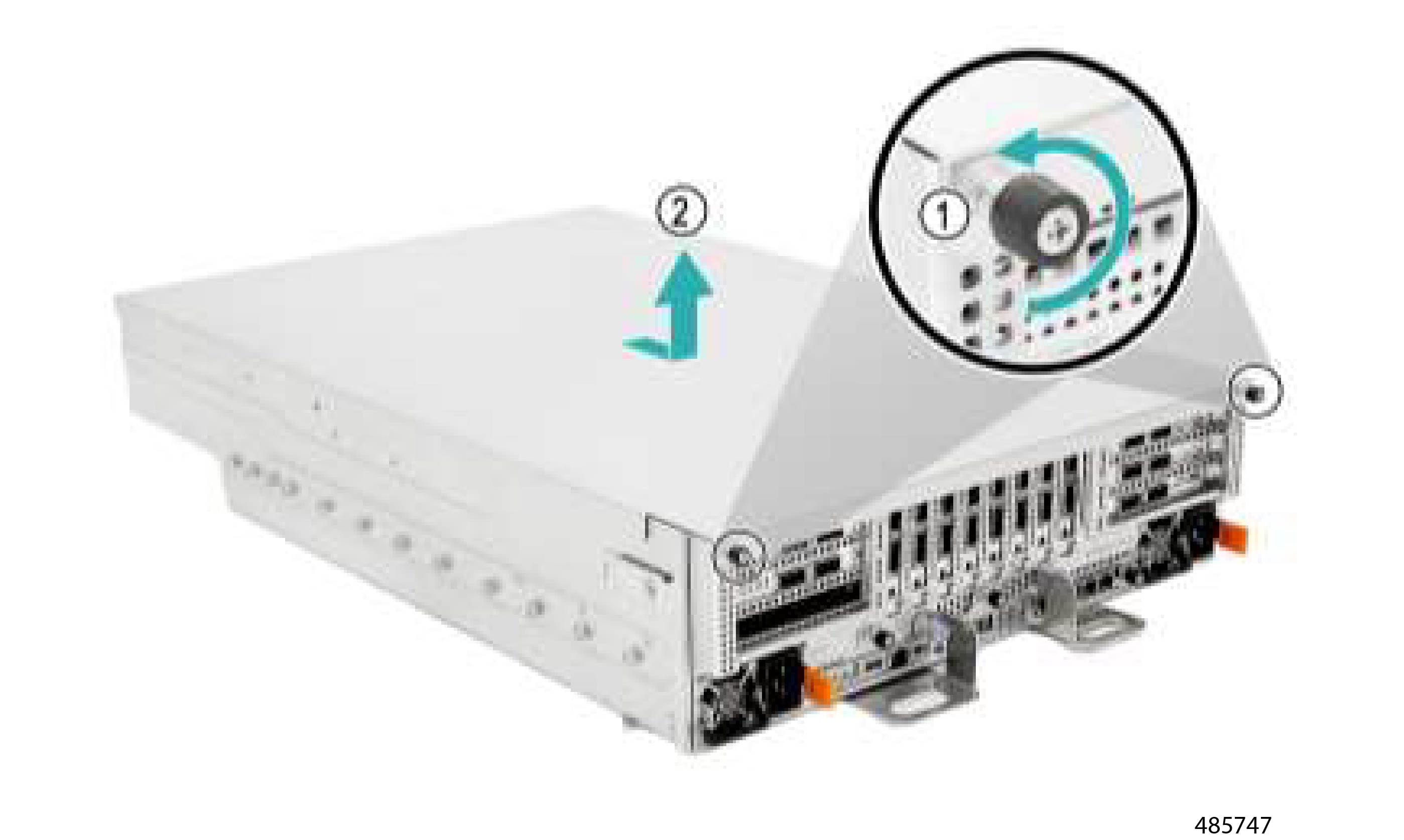
The server is heavy! Do not attempt to unrack or lift the server by yourself. Use a server lift, scissors jack, or some other mechanical tool to lift and support the server while inserting, moving, or removing it.


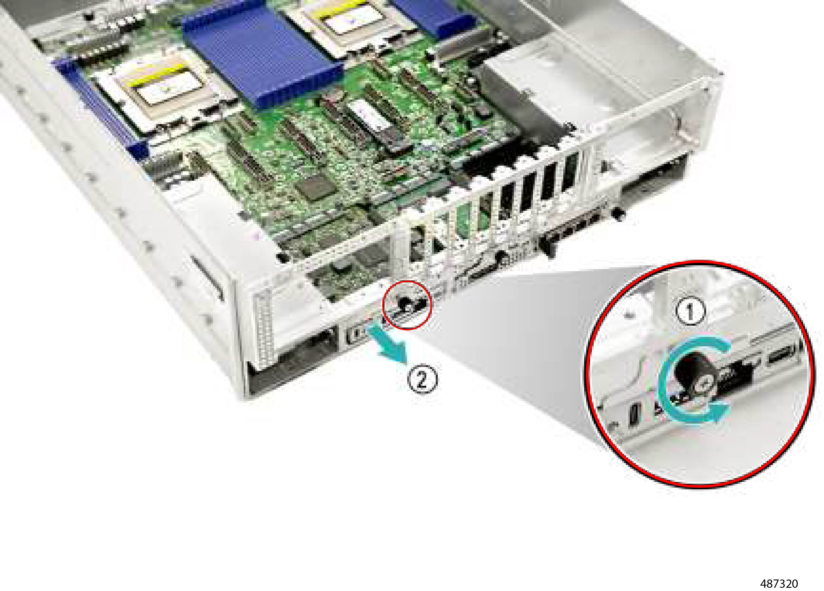
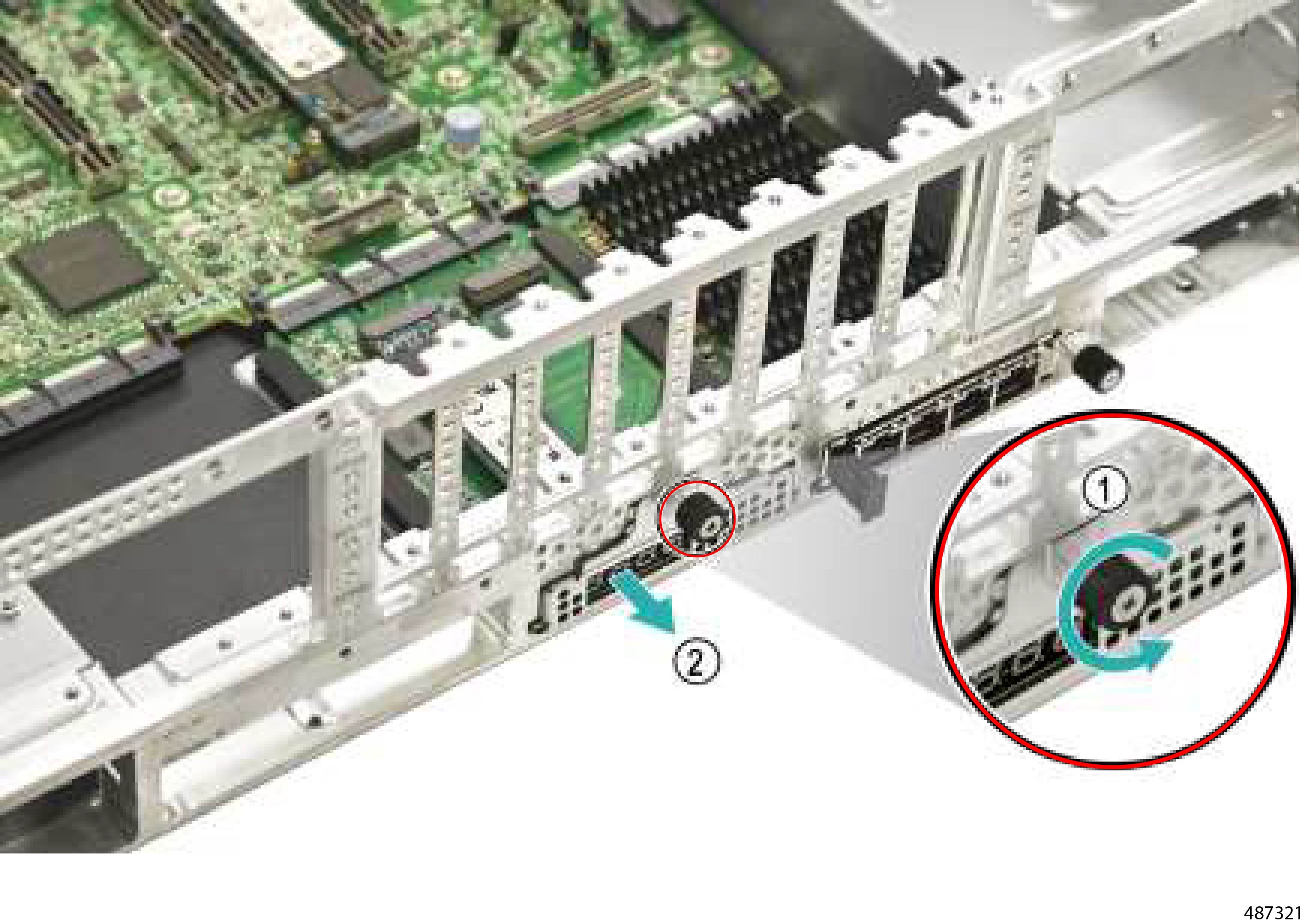
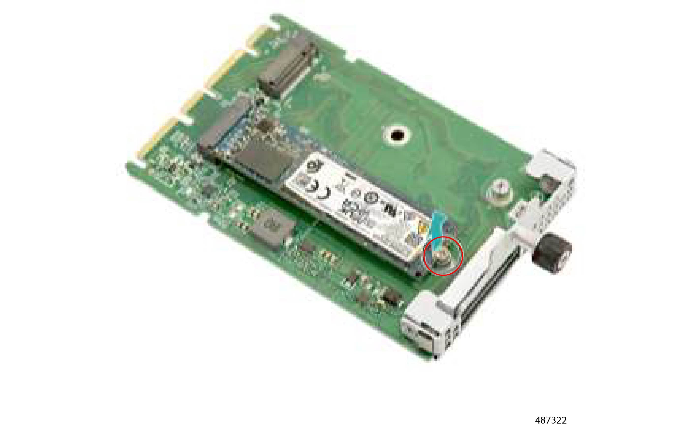
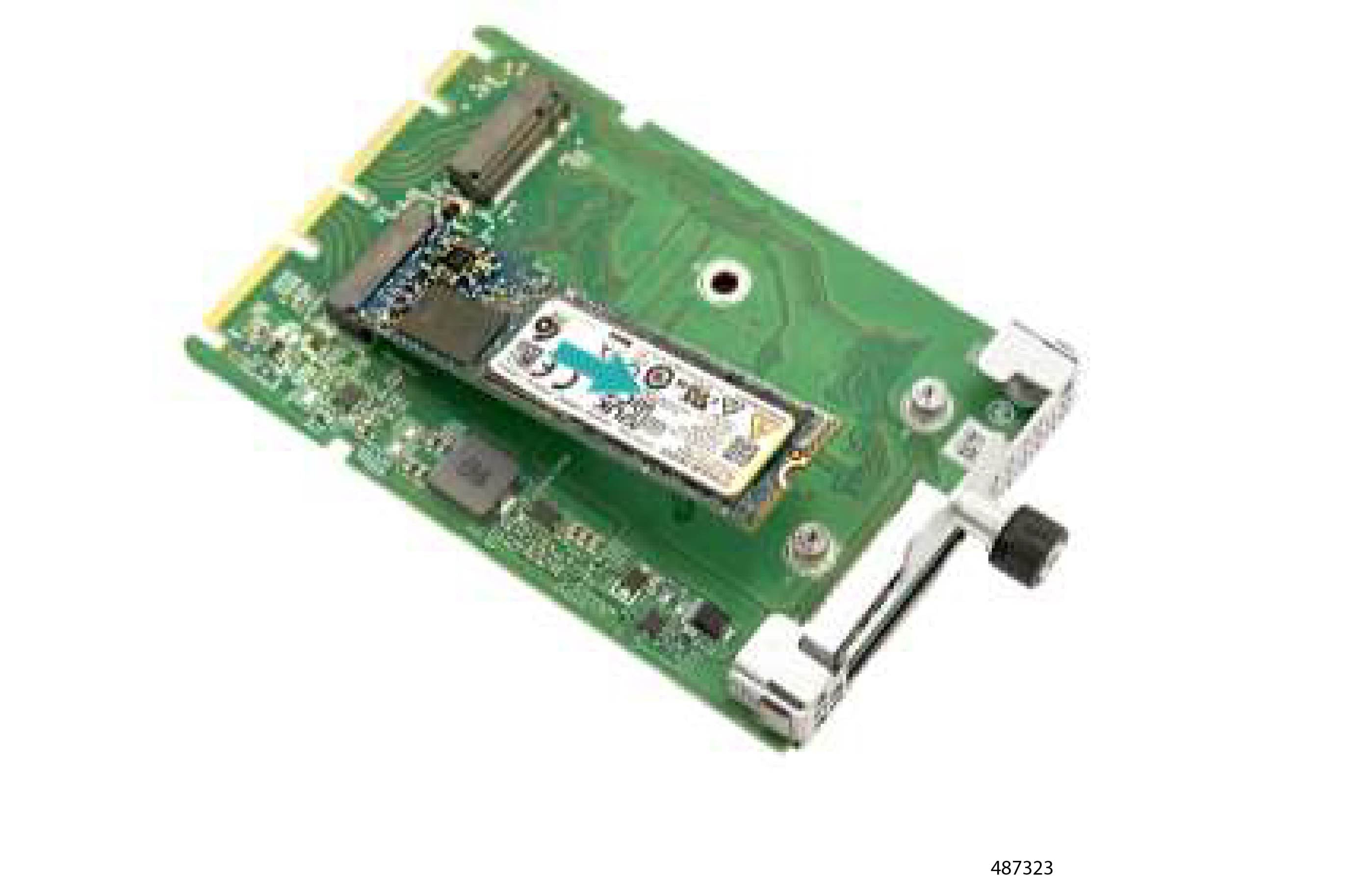
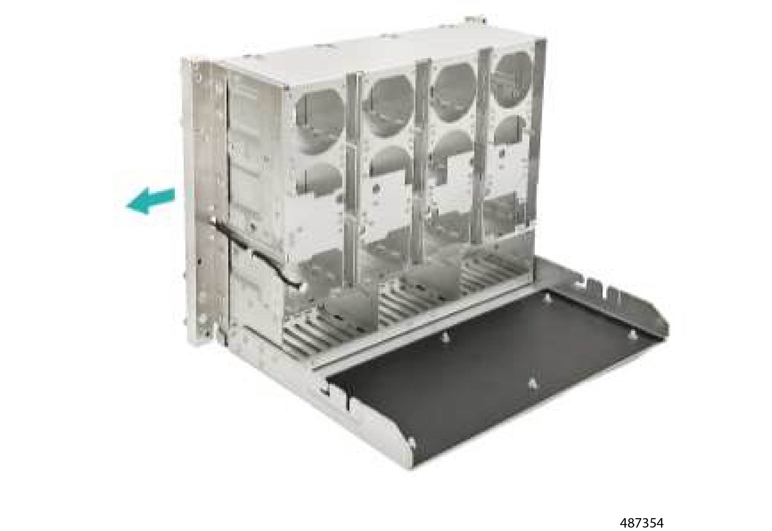
The server has various components that can be recycled. When recycling the server and its components, always comply with your local laws governing recycling and e-waste.


Warning


The procedures in this chapter are destructive and can render the server unusable, so this content is not for standard use or FRU procedures! These procedures are for recyclers only!


Removing the Top Cover

The server chassis has a top sheetmetal cover that is secured by two M3xL10.2 mm thumb screws.

Gather a #2 Phillips screwdriver before starting this procedure.

Procedure


Step 1

Using the screwdriver, remove the two thumbscrews.

Figure 1. Location of Thumbscrews

Step 2

Grasp the top cover and slide it forward, then lift up to remove it from the server chassis.

Figure 2. Removing the Top Cover

What to do next

Continue with your recycling process. See the relevant section.

Recycling the Mainboard and SAS IO Board PCBs

The server mainboard and SAS I/O board are attached to the server main sheetmetal tray. Both PCBs can be detached and recycled, but both boards required removal of other components.

To recycle the Mainboard and SAS I/O board, use the following procedures in the order shown.

Removing the Air Baffle

The server features an air baffle for optimized ventilation. The air baffle is secured by eight (8) M3x L6mm Phillips screws.

Gather a #2 Phillips head screwdriver before attempting this procedure.

Before you begin


Warning


For Recyclers Only! This procedure is not a standard field-service option. This procedure is for recyclers who will be reclaiming the electronics for proper disposal to comply with local eco design and e-waste regulations.


Procedure


Step 1

Using the screwdriver, remove all the screws.

Step 2

Grasp the air baffle and lift it up to remove it from the chassis.

Figure 3. Removing the Air Baffle

What to do next

Removing the CEM Top Cover

Removing the CEM Top Cover

The CEM Board has its own sheetmetal cover that must be removed to gain access to the fasteners that secure the CEM to the server.

The CEM cover is secured by:

  • Six (6) M3xL6mm Phillips screws

  • Two (2) M3x L10.2 thumb screws

Gather a #2 Phillips screwdriver before attempting this procedure.

Before you begin


Warning


For Recyclers Only! This procedure is not a standard field-service option. This procedure is for recyclers who will be reclaiming the electronics for proper disposal to comply with local eco design and e-waste regulations.


Procedure


Step 1

Using the screwdriver, remove the six M3xL6mm Phillips screws (1).

Step 2

Using the screwdriver or your fingers, remove the two M3x L10.2 thumb screws (2).

Step 3

When all screws are removed, grasp the CEM top cover and lift it up (3).

Figure 4. Removing the CEM Top Cover

What to do next

Removing the PCIe Card

Removing the PCIe Card

The server has eight (8) PCIe cards, each secured by one M3x L4mm Phillips screw, for a total of eight screws.

Before you begin


Warning


For Recyclers Only! This procedure is not a standard field-service option. This procedure is for recyclers who will be reclaiming the electronics for proper disposal to comply with local eco design and e-waste regulations.


Gather a #2 Phillips screwdriver.

Procedure


Step 1

Using the screwdriver, remove the PCIe card's securing screw.

Step 2

Grasping the card by the handle, keep the card vertical while lifting straight up to disconnect it from its socket and remove it from the chassis.

Figure 5. Removing the PCIe Cards

Step 3

Repeat this procedure, as needed, for each PCIe card.


What to do next

Removing the Mini Cool Edge Cables

Removing the Mini Cool Edge Cables

The server has a total of sixteen (16) Mini Cool Edge Cables arranged vertically so that half the cables (the top cables) are installed on top of the other half (the bottom cables). The top row contains eight (8) cables, and the bottom row contains eight (8) cables.

For the top row of eight cables:

  • One end of each cable terminates in a connector that inserts vertically into a socket on the Host Interface Board (HIB).

  • The other end of each cable terminates on the CEM Base Board.

This procedure enables you to remove the top row of Mini Cool Edge cables. For the procedure to remove the other Mini Cool Edge cables, go to:

Before you begin


Warning


For Recyclers Only! This procedure is not a standard field-service option. This procedure is for recyclers who will be reclaiming the electronics for proper disposal to comply with local eco design and e-waste regulations.


Procedure


Step 1

Locate the top row of eight cables.

Figure 6. Location of Mini Cool Edge Cables

Step 2

Grasp each cable by the connector that attaches to the HIB board.

Caution


Do not attempt to disconnect the cable from the CEM Module end!

Step 3

Holding the cable connector vertical, pull straight up until it disconnects from the socket on the HIB.

Step 4

Repeat this procedure for each cable.


What to do next

Removing the CEM Base Board

Removing the CEM Base Board


Caution


The CEM Base Board supports Mini Cool Edge cables that terminate on the CEM Base Board and on the HIB. If you have not already disconnected the Mini Cool Edge cables from the HIB, do so now.


The CEM Base board is secured to the server by ten (10) M3xL6mm Phillips screws.

Before you begin


Warning


For Recyclers Only! This procedure is not a standard field-service option. This procedure is for recyclers who will be reclaiming the electronics for proper disposal to comply with local eco design and e-waste regulations.


Gather a #2 Phillips screwdriver.

Procedure


Step 1

Using the screwdriver, remove the M3xL6mm screws.

Figure 7. Location of Screws

Step 2

Grasping the CEM Base Board by its edges, lift it straight up to remove it from the server.

The top row of eight cables should also come out of the chassis with the CEM Base Board when it disconnects from the server.

Figure 8. Removing the CEM Base Board

Step 3

Disconnect the cables from the CEM Base Board by using the connector latches.

  1. Locate each connector latch.

  2. Press down on the latch to open it.

  3. While holding the latch open, pull the cable out of the connector.

    Figure 9. Removing the Power Cable

Step 4

Repeat this procedure for each cable attached to the CEM Base Board.


What to do next

Removing the Main Power Cable

Removing the Main Power Cable

The server has multiple different power cables that connect to the rear of each power supply (PSU).

Use the following procedure to remove a power cable.

Before you begin


Warning


For Recyclers Only! This procedure is not a standard field-service option. This procedure is for recyclers who will be reclaiming the electronics for proper disposal to comply with local eco design and e-waste regulations.


Procedure


Step 1

Locate the power cable and the power cable connector.

Figure 10. Location of Power Cable and Power Cable Connector

Step 2

Disconnect the power cable from the PSU by using the connector latch.

  1. Locate the connector latch.

  2. Press down on the latch to open it.

  3. While holding the latch open, pull the cable out of the connector.

    Figure 11. Detaching the Power Cable from the Connector

Step 3

Repeat this procedure for each power cable.


What to do next

Removing CNPWR1 and PWR2 Cable

Removing CNPWR1 and PWR2 Cable

The server has multiple power cables that enable distribution of power to different PCBs and components.

Use the following procedure to disconnect the power cable that attaches to connectors CNPWR1 and PWR2.

Before you begin


Warning


For Recyclers Only! This procedure is not a standard field-service option. This procedure is for recyclers who will be reclaiming the electronics for proper disposal to comply with local eco design and e-waste regulations.


Procedure


Step 1

Locate the power cable.

Step 2

Disconnect the power cables from the CEM Base Board by using the connector latches.

  1. Locate each connector latch.

  2. Press down on the latch to open it.

  3. While holding the latch open, pull the cable out of the connector.

    Figure 12. Detaching the Cable from the Connector

Step 3

After the cable is disconnected, release it from the T1 cable clip.

Figure 13. Disconnecting the Cable Clip

What to do next

Removing CNCR1 and CNCR2 Mini Cool Edge Cable

Removing CNCR1 and CNCR2 Mini Cool Edge Cable

The server has multiple sets of Mini Cool Edge cables.

  • Two cables on the bottom row attach to the CNCR1 and CNCR2 connectors.

  • One end of each cable connects to the HIB.

  • The other end of the cable connects to the CEM.

Use the following procedure to remove the cables.

Before you begin


Warning


For Recyclers Only! This procedure is not a standard field-service option. This procedure is for recyclers who will be reclaiming the electronics for proper disposal to comply with local eco design and e-waste regulations.


Procedure


Step 1

Grasp each cable by the connector that attaches to the HIB board.

Caution


Do not attempt to disconnect the cable from the CEM Module end!

Step 2

Holding the cable connector vertical, pull straight up until it disconnects from the connector on the HIB.

Figure 14. Disconnecting the Cable Connector

Step 3

Repeat this procedure to disconnect both cables from the HIB.

Step 4

When the cables are disconnected from the HIB, release the cables from the T16 and T20 cable clips.


What to do next

Removing CNCL1 and CNCL2 Mini Cool Edge Cables

Removing CNCL1 and CNCL2 Mini Cool Edge Cables

The server has multiple sets of Mini Cool Edge cables.

  • Two cables on the bottom row attach to the CNCL1 and CNCL2 connectors.

  • One end of each cable connects to the HIB.

  • The other end of the cable connects to a CEM.

Use the following procedure to remove the cables.

Before you begin


Warning


For Recyclers Only! This procedure is not a standard field-service option. This procedure is for recyclers who will be reclaiming the electronics for proper disposal to comply with local eco design and e-waste regulations.


Procedure


Step 1

Grasp each cable by the connector that attaches to the HIB board.

Caution


Do not attempt to disconnect the cable from the CEM Module end!

Step 2

Holding the cable connector vertical, pull straight up until it disconnects from the connector on the HIB.

Figure 15. Disconnecting the Cable Connector from the HIB

Step 3

Repeat this procedure to disconnect both cables from the HIB.

Step 4

When the cables are disconnected from the HIB, release the cables from the T4 and T10 cable clips.

Figure 16. Removing the Cables from the Cable Clips

What to do next

Removing the HIB Module

Removing the HIB Module

The Host Interface Board (HIB) Module is secured to the server by eight (8) M3x L6mm Phillips screws plus six (6) T Pins, three on each of two sides of the module.

Before you begin


Warning


For Recyclers Only! This procedure is not a standard field-service option. This procedure is for recyclers who will be reclaiming the electronics for proper disposal to comply with local eco design and e-waste regulations.


Gather a #2 Phillips screwdriver before starting this procedure.

Procedure


Step 1

Using the screwdriver, remove the eight M3x L6mm screws.

Step 2

Release the T Pins on each side.

Step 3

Slide the HIB module forward then up to lift it off of the server.

Figure 17. Removing the HIB Module

What to do next

Removing the Air Baffle Module

Removing the Air Baffle Module

The air baffle module sits on top of the cable holder and spans the width of the server. The module is secured to the server by eight (8) M3xL6mm Phillips screws on the top of the air baffle module and four M3xL6mm Phillips screws, two each on the sides of the air baffle module that contact the server's sheetmetal walls.

Before you begin


Warning


For Recyclers Only! This procedure is not a standard field-service option. This procedure is for recyclers who will be reclaiming the electronics for proper disposal to comply with local eco design and e-waste regulations.


Gather a #2 Phillips screwdriver before starting this procedure.

Procedure


Step 1

Using the screwdriver, remove the eight M3xL6mm screws on the top of the module.

Figure 18. Removing the Screws

Step 2

Using the screwdriver, remove the four M3xL6mm screws on the sides of the server.

Step 3

Grasp the air baffle module by the edges and lift it off of the server.

Figure 19. Removing the Air Baffle Module

What to do next

Removing the Cable Holder Cover

Removing the Cable Holder Cover

The cable holder cover rests in the server and is not secured by any fasteners.

Before you begin


Warning


For Recyclers Only! This procedure is not a standard field-service option. This procedure is for recyclers who will be reclaiming the electronics for proper disposal to comply with local eco design and e-waste regulations.


Procedure


Step 1

If you have not already done so, remove the Air Baffle Module..

See Removing the Air Baffle Module.

Step 2

Grasp the cable holder cover and lift it up to remove it.

Figure 20. Removing the Cable Holder Cover

What to do next

Removing the PWR1 and PWR6 Power Cable

Removing the PWR1 and PWR6 Power Cable

The server has multiple power cables. Use this procedure to remove the power cable that spans between the PWR1 and HPM PWR6 connectors.

Before you begin


Warning


For Recyclers Only! This procedure is not a standard field-service option. This procedure is for recyclers who will be reclaiming the electronics for proper disposal to comply with local eco design and e-waste regulations.


Procedure


Step 1

Locate the power cable.

Figure 21. Location of the Power Cable

Step 2

Disconnect the power cable by using the connector latch.

  1. Locate the connector latch.

  2. Press down on the latch to open it.

  3. While holding the latch open, pull the cable out of the connector.

    Figure 22. Disconnecting the Cable from the Cable Connector

What to do next

Removing the Right CEM Module

Removing the Right CEM Module

The server has multiple CEM Modules which occupy the right and left sides of the server. Right and left are in relation to the rear of the server.

The CEM on the right side of the server is secured by four (4) M3x L6mm Phillips screws, two screws on the server's sheetmetal side wall and two on the front faceplate of the server.

Gather a #2 Phillips screwdriver before starting this procedure.

Before you begin


Warning


For Recyclers Only! This procedure is not a standard field-service option. This procedure is for recyclers who will be reclaiming the electronics for proper disposal to comply with local eco design and e-waste regulations.


Gather a #2 Phillips screwdriver before starting this procedure.

Procedure


Step 1

Using the screwdriver, remove all four M3x L6mm screws.

Step 2

Grasping the CEM Module, lift if straight up out of the server.

Figure 23. Removing the Right CEM Module

What to do next

Removing the SAS Cable

Removing the SAS Cable

The server has a power cable that provides power to the SAS Interposer card (SAS cable). The SAS cable connects to the CN1 and C1 connectors. Each end of the cable terminates at a latch connector.

Use the following procedure to disconnect the SAS cable.

Before you begin


Warning


For Recyclers Only! This procedure is not a standard field-service option. This procedure is for recyclers who will be reclaiming the electronics for proper disposal to comply with local eco design and e-waste regulations.


Procedure


Step 1

Locate the SAS cable and connectors.

Step 2

Disconnect the power cable from the PSU by using the connector latch.

  1. Locate the connector latch.

  2. Press down on the latch to open it.

  3. While holding the latch open, pull the cable out of the connector.

    Figure 24. Disconnecting the Cable from the Connector

What to do next

Removing the PWR1 and PWR5 Cable

Removing the PWR1 and PWR5 Cable

The server has multiple power cables, including a power cable that connects to the BF3 card through the PWR1 and PWR5 connectors.

Before you begin


Warning


For Recyclers Only! This procedure is not a standard field-service option. This procedure is for recyclers who will be reclaiming the electronics for proper disposal to comply with local eco design and e-waste regulations.


Procedure


Step 1

Locate the cable.

Step 2

Disconnect the power cable from the PSU by using the connector latch.

  1. Locate the connector latch.

  2. Press down on the latch to open it.

  3. While holding the latch open, pull the cable out of the connector.

    Figure 25. Disconnecting the Cable from the Connector

Step 3

When the cable is disconnected, release it from the B1 cable clip.

Figure 26. Removing the Cable from the Cable Clip

What to do next

Removing the PCIE12 Mini Cool Edge Cable

Removing the PCIE12 Mini Cool Edge Cable

The server has multiple Mini Cool Edge cables, including the cable that connects to the PCIE12 connector. This cable is not one of the 16 in the top and bottom rows that connect to the HIB module. Instead, it connects to the main motherboard.

Before you begin


Warning


For Recyclers Only! This procedure is not a standard field-service option. This procedure is for recyclers who will be reclaiming the electronics for proper disposal to comply with local eco design and e-waste regulations.


Procedure


Step 1

Locate the cable.

Figure 27. Location of the PCIe12 Mini Cool Edge Cable

Step 2

Grasp the cable by the connector at one end and lift up to disconnect it.

Step 3

Grasp the cable by the other connector and lift up to disconnect it.

Step 4

When both ends of the cable are disconnected, release it from the B2 cable clip.

Figure 28. Removing the Cable from the Cable Clip

Step 5

With both ends of the cable disconnected, remove the cable by pulling straight up to lift it out of the server.


What to do next

Removing the Left CEM Module

Removing the Left CEM Module

The server has multiple CEM Modules which occupy the right and left sides of the server. Right and left are in relation to the rear of the server.

The CEM on the left side of the server is secured by four (4) M3x L6mm Phillips screws, two screws on the server's sheetmetal side wall and two on the front faceplate of the server.

Gather a #2 Phillips screwdriver before starting this procedure.

Before you begin


Warning


For Recyclers Only! This procedure is not a standard field-service option. This procedure is for recyclers who will be reclaiming the electronics for proper disposal to comply with local eco design and e-waste regulations.


Procedure


Step 1

Using the screwdriver, remove all four M3x L6mm screws.

Step 2

Grasping the CEM Module, lift it straight up out of the server.

Figure 29. Removing the Left CEM Module

What to do next

Removing the CEM Crossbar

Removing the CEM Crossbar

The CEM crossbar is a metal piece that spans the width of the server and provides support and attachment points for the CEM Modules. The CEM Crossbar is secured to the server by twelve M3x L4mm Phillips screws.

Before you begin


Warning


For Recyclers Only! This procedure is not a standard field-service option. This procedure is for recyclers who will be reclaiming the electronics for proper disposal to comply with local eco design and e-waste regulations.


Gather a #2 Phillips screwdriver before starting this procedure.

Procedure


Step 1

Locate the screws.

Figure 30. Location of the Screws

Step 2

Using the screwdriver, remove the twelve screws, then lift the CEM crossbar out of the server.

Figure 31. Removing the CEM Crossbar

What to do next

Removing the PCIE11 and PCIE15 and PCIE16 Power Cable

Removing the PCIE11 and PCIE15 and PCIE16 Power Cable

The server has multiple power cable, including a Y cable that connects at one end to the PCIE11 connector, and connects the other ends to the PCIE15 and PCIE16 connectors.

Before you begin


Warning


For Recyclers Only! This procedure is not a standard field-service option. This procedure is for recyclers who will be reclaiming the electronics for proper disposal to comply with local eco design and e-waste regulations.


Procedure


Step 1

Locate the cable.

Figure 32. Location of the PCIe11, 15 and 16 Power Cable

Step 2

Disconnect the cable by pulling up on each of the connectors.

Step 3

When the cable is disconnected, release the cable from the B4 cable clip and lift the cable out of the server.

Figure 33. Removing the Cable from the Cable Clip

What to do next

Removing the Air Baffle and Cable Holder

Removing the Air Baffle and Cable Holder

The air baffle and cable holder are a single molded piece that provide optimal airflow and gather and organize cables that run through the middle of the server. This single part is secured to the server by two (2) M3x L10.2mm Phillips thumb screws.

Before you begin


Warning


For Recyclers Only! This procedure is not a standard field-service option. This procedure is for recyclers who will be reclaiming the electronics for proper disposal to comply with local eco design and e-waste regulations.


Gather a #2 Phillips screwdriver before starting this procedure.

Procedure


Step 1

Locate the M3x L10.2mm thumbscrews.

Figure 34. Location of the Thumbscrews

Step 2

Using the screwdriver, remove the two thumbscrews and lift the air baffle and cable holder out of the server.

Figure 35. Removing the Air Baffle and Cable Holder

What to do next

Removing the CPU Heatsink and CPU Module

Removing the CPU Heatsink and CPU Module

Each of the server's CPUs has a heatsink that rests on top of the CPU. Each heatsink is secured to the server by six captive Phillips heatsink screws, for a total of 12 screws in a dual-CPU configuration.

The screws secure through the heatsink into the retention frame on the socket so that the CPU is secured into the socket by the same set of screws.

Before you begin


Warning


For Recyclers Only! This procedure is not a standard field-service option. This procedure is for recyclers who will be reclaiming the electronics for proper disposal to comply with local eco design and e-waste regulations.


Gather a #2 Phillips screwdriver before attempting this procedure.

Procedure


Step 1

Locate the screws.

Figure 36. Location of the Screws

Step 2

Using the screwdriver, remove the screws.

Step 3

Lift the heatsinks off of the server.

Step 4

Grasp the CPU and retention frame and lift them up to disconnect them from the CPU socket and remove them from the server.

Figure 37. Removing the Heatsinks

What to do next

Recycling the Main Board and SAS IO Board

Recycling the Main Board and SAS IO Board

The server's main motherboard and SAS I/O Board are connected to the server's sheet metal bottom by the following fasteners:

  • 21 M3x L6mm Phillips screws

  • Two (2) 3x L5.5 mm Phillips thumb screws.

  • Two (2) M3x L11.9 mm Phillips thumb screws

Gather a #2 Phillips screwdriver before starting this procedure.

Before you begin


Warning


For Recyclers Only! This procedure is not a standard field-service option. This procedure is for recyclers who will be reclaiming the electronics for proper disposal to comply with local eco design and e-waste regulations.


Procedure


Step 1

Locate the screws.

Figure 38. Location of the Screws

Indicator

Fastener

Cyan Circle

M3x L6mm screws (21)

Red Circle

M3x L5.5mm screws (2)

Yellow Circle

M3x L11.9mm screws (2)

Step 2

Using a screwdriver, remove all screws and disconnect the boards from the server sheetmetal.


Recycling HGBB Module

Use this task to detach the HGBB Tray's PCB for recycling.


Warning


The HGBB tray is heavy! Never attempt to lift or maneuver the tray by yourself! Instead, use a lift, scissors jack, or some other device to lift and bear the weight of the HGBB tray while you are installing or servicing it. If you must lift or handle the tray without mechanical assistance, use two or more people to lift and handle server. Always use safe lifting practices when lifting or moving the HGBB tray.


Before you begin

If you have not already done so, remove power from the server.

For this procedure, gather a #2 Phillips screwdriver.

Procedure


Step 1

Remove the HGBB Tray:

  1. Using the screwdriver or your fingers, loosen the two thumbscrews.

  2. Pull the tray handle to detach the HGBB Tray from the main chassis assembly.

    Figure 39. Removing the HGBB Tray

Step 2

Using a #2 Phillips screwdriver or your fingers, loosen the two screws.

Step 3

When the screws are removed, slide the tray cover backwards and up to detach it from the HGBB tray.

Figure 40. Removing the HGBB Access Panel

Step 4

Remove the HGBB Tray bracket.

  1. Using the screwdriver or your fingers, disengage the latch on both sides of the tray.

  2. Detach the bracket from the HGBB tray.

    Figure 41. Detaching the Bracket

Step 5

Remove the HGBB module from the tray.

  1. Using a Phillips screwdriver, loosen the captive screws.

    Figure 42. Loosening the Screws

Step 6

Grasp the built-in handles and lift the HGBB module from the tray.

Figure 43. Removing the HGBB Module

Step 7

Recycle the HGBB module and tray in accordance with local ewaste and recycling regulations.


Recycling the CPU Tray PCB

Use this task to detach the HGBB Tray's PCB for recycling.


Warning


The HGBB tray is heavy! Never attempt to lift or maneuver the tray by yourself! Instead, use a lift, scissors jack, or some other device to lift and bear the weight of the HGBB tray while you are installing or servicing it. If you must lift or handle the tray without mechanical assistance, use two or more people to lift and handle server. Always use safe lifting practices when lifting or moving the HGBB tray.


Before you begin

If you have not already done so, remove power from the server.

For this procedure, gather a #2 Phillips screwdriver and a T20 Torx screwdriver (for heatsinks and CPUs). An alcohol swab or CPU cleaning pad will be useful, but not required, to clean up thermal grease between the CPU and heatsink.

Procedure


Step 1

Remove the CPU Tray:

  1. Loosen the two thumbscrews.

  2. Simultaneously pull each tray handle to detach the CPU Tray from the chassis.

    Figure 44. Removing the CPU Tray

Step 2

Replace the CPU Tray:

  1. Insert the CPU Tray into the chassis.

  2. Simultaneously, push each tray handle inwards until they latch into place.

  3. Tighten the two (2) thumbscrews to secure the CPU Tray to the chassis.

    Figure 45. Replacing the CPU Tray

Step 3

Remove the access panel from the CPU tray.

  1. Using a Phillips screwdriver or your fingers, loosen the thumbscrews.

  2. Slide the access panel backward and up to detach it from the tray.

    Figure 46. Removing the CPU Tray Access Panel

Step 4

Remove the air baffle.

  1. Using a screwdriver, remove the eight screws.

    Figure 47. Location of the Screws
  2. Grasp the air baffle and lift it up to detach it from the tray.

    Figure 48. Removing the Air Baffle

Step 5

Remove the HIB Module.

  1. Disconnect the data cables.

    Figure 49. Disconnecting the Cables
  2. Disconnect the power cable from the HIB module.

    Figure 50. Disconnecting the Power Cable
  3. Using a Phillips screwdriver, remove the eight screws along the sidewalls of the tray.

    Figure 51. Location of the Screws
  4. Disconnect the power cable from the HIB module.

    Figure 52. Disconnecting the Power Cable
  5. Using a Phillips screwdrivers, remove the 25 screws.

    Figure 53. Location of the Screws
  6. Detach the HIB module from the sheetmetal bracket.

    Figure 54. Detaching the HIB from the Bracket

Step 6

Remove the SAS I/O board.

  1. Disconnect the data cable.

    Figure 55. Disconnecting the Cable
  2. Using a Phillips screwdriver, remove the four screws.

    Figure 56. Location of the Screws
  3. Grasp the SAS I/O board and lift it up to detach it from the sheetmetal.

    Figure 57. Removing the SAS I/O Board

Step 7

Remove the Middle Air Baffle.

  1. Using a Phillips screwdriver, remove the 12 screws.

    Note


    Four screws (2 per side) are located on each of the server's sidewalls.

    Figure 58. Location of the Screws
  2. Grasp the middle air baffle and lift it up to detach it from the server.

    Figure 59. Removing the Middle Air Baffle

Step 8

Remove the cable holder assembly.

  1. Disconnect the power cables from the CPU Tray's motherboard.

    Figure 60. Disconnecting the Cables
  2. Remove the cable holder cover (1) and cable clips (2).

    Figure 61. Removing the Cable Holder Cover and Cable Clips
  3. Using a Phillips screwdriver, loosen the two thumbscrews (1), remove the two screws (2), and detach the cable holder (3).

    Figure 62. Locations of the Screws and Cable Holder

Step 9

Grasp the bottom air baffle and lift it up to remove it.

Figure 63. Removing the Bottom Air Baffle

Step 10

Remove the heatsink from the CPU.

  1. Using a T20 Torx screwdriver, loosen the heatsink screws in the order shown (a typical star pattern).

    Figure 64. Loosening the Heatsink Screws
  2. Carefully, grasp the heatsink by the edges and lift it up to detach it from the CPU.

    Figure 65. Removing the Heatsink
  3. Repeat this step for each other heatsink in the server.

Step 11

Remove the processor.

  1. Loosen the captive screw.

    Figure 66. Loosening the Screw
  2. Open the CPU cover plate.

    Figure 67. Opening the CPU Cover Plate
  3. Carefully remove the processor.

    Figure 68. Removing the Processor
  4. Repeat this step for the other CPU.

Step 12

Remove the DIMM Module

  1. Press the retention clips on both sides of the DIMM slot outward.

  2. Grasp the DIMM module and lift it up to remove it from the DIMM slot.

    Figure 69. Removing a DIMM Module
  3. Repeat this step for each other DIMM module in the server.

Step 13

When the module and sheetmetal are separated, recycle them in accordance with your local ewaste and recycling regulations.


What to do next

Continue CPU Tray disassembly for recycling by Recycling the PCIe Card PCBs.

Recycling the PCIe Card PCBs

The CPU Tray contains multiple PCIe PCBs. Use the following procedure to remove the PCIe cards and recycle their PCBs.

Recycling the PCIe Card PCBs

The server has multiple PCIe cards in the CPU tray. You can use this procedure to remove them for recycling, or as part of the overall procedure to recycle the CPU Tray PCBs.

Regardless of how you will use this procedure, make sure to comply with all recycling and ewaste laws for your locale.

Before you begin

If you have not already done so, remove the CPU Tray's top cover.

You will find it helpful to gather a #2 Phillips screwdriver before attempting this procedure.

Procedure


Step 1

Using a Phillips screwdriver, loosen the two thumbscrews (1) and four screws (2) for the eight CEM baseboards.

Figure 70. Loosening the Thumbscrew and Screws

Step 2

Slide the CEM BB access panel back and up to detach it from the server.

Figure 71. Removing the CEM Base Board Access Panel

Step 3

Using a Phillips screwdriver, remove the eight screws (1) and lift each PCIe card out of the server.

Figure 72. Location of the PCIe Card Screws and Removing the PCIe Cards

Step 4

Remove the CEM Riser Assembly.

  1. Using a Phillips screwdriver, loosen the thumbscrew (1) and the four screws.

    Figure 73. Loosening the Thumbscrew and Location of the Screws
  2. Grasp the CEM Riser Assembly and lift it out of the server.

    Figure 74. Removing the CEM Riser Assembly (Right CEM)
  3. Repeat this step for each CEM Riser Assembly.

Step 5

Remove the PCIe Cards from the CEM Riser.

  1. Remove the two or three screws (depending on how many PCIe cards are installed).

  2. Detach the PCIe cards from the riser assembly.

    Figure 75. Removing PCIe Cards
  3. Repeat this step for each PCIe card.

Step 6

Remove the CEM Riser board.

  1. Using a Phillips screwdriver, remove the six screws.

    Figure 76. Location of the Screws
  2. Detach the CEM Riser board from the bracket.

    Figure 77. Removing the CEM Riser
  3. Repeat this step for the other CEM Riser board.

Step 7

Remove the CEM 8X base board.

  1. Using a screwdriver, remove the ten screws.

    Figure 78. Location of the Screws
  2. Disconnect the power cord for the CEM 8X base board.

    Figure 79. Disconnecting the Power Cord

Step 8

Remove the CEM Crossbar.

  1. Remove the twelve screws.

    Figure 80. Location of the Screws
  2. Grasp the CEM Crossbar and lift it up to remove it from the server.

    Figure 81. Removing the CEM Crossbar

Step 9

Remove the DC-SCM Module.

  1. Using a Philips screwdriver or your fingers, loosen the thumbscrew.

  2. Remove the DC-SCM Module from the server.

Figure 82. Removing the DSC-SCM Module

Step 10

Remove the Dual M.2 Module.

  1. Using a Philips screwdriver or your fingers, loosen the thumbscrew.

  2. Remove the Dual M.2 Module from the server.

    Figure 83. Removing the Dual M.2 Module
  3. (Optional) Using a Phillips screwdriver, loosen the screw.

    Figure 84. Location of the Retaining Screw
  4. Lift the SSD off of the Dual M.2 Module.

    Figure 85. Removing the SSD from the M.2 Module

Step 11

Remove the NIC Module.

  1. Using a screwdriver or your fingers, loosen the screw.

  2. Press the ejector.

  3. Grasp the module and slide it out of the server.

    Figure 86. Removing the NIC Module

Step 12

(Optional) Remove the SSD on the Mainboard.

  1. Using a Phillips screwdriver, loosen the screw.

    Figure 87. Location of the Retaining Screw
  2. Lift the SSD module off of the mainboard.

    Figure 88. Removing the SSD from the Mainboard

Step 13

Remove the CPU Support Bracket.

  1. Using a screwdriver, remove the six screws.

    Four of the six screws are in pairs on each sidewall.

    Figure 89. Location of the Screws
  2. Using a screwdriver, remove the screws and release the catch pins to detach the CPU Support Bracket.

    Figure 90. Location of the Screws and Catch Pins

Step 14

Remove the mainboard.

  1. Using a screwdriver or your fingers, loosen the two thumbscrews and detach the mainboard from the CPU Tray.

    Figure 91. Location of the Screws and Removal of the Mainboard
  2. Using a Phillips screwdriver, loosen the two thumbscrews and remove the twenty screws.

    Figure 92. Location of the Thumbscrews and Screws
  3. Grasp the Mainboard and Bracket and separate them.

    Figure 93. Detaching the Mainboard from the Bracket

Step 15

Recycle the Mainboard and all other recyclable parts and components in accordance with your local recycling and ewaste regulations.


Recycling PSUs

The server supports two different types of power supplies (PSUs):

  • Six 54V 3000W (N+2) AC PSUs (All SKUs)

  • Two 12V 2700W (N+1) PSUs (EU SKUs)

PSUs are FRUs, which can be removed from the server for proper ewaste and recycling.

Procedure


Step 1

Remove the PSUs from the server chassis.

Step 2

When the PSUs are removed from the chassis, dispose of them in compliance with your local ewaste and recycling regulations.


Recycling SAS or NVMe SSDs

The server contains data storage in hot-swappable SAS or NVMe SSDs in the front-mounted drives.

Use this procedure to remove the SSDs for recycling.

Before you begin

This procedure requires access to the front of the server. If you haven't already removed the front bezel, do so now.

For this procedure, gather a #2 Phillips screwdriver.

Procedure


Step 1

With the front bezel removed, remove the SAS/NVMe SSD carrier from the server.

  1. Push the drive carrier button to disengage the carrier assembly from the server chassis.

  2. Grasp the drive carrier bezel and pull it outward.

  3. Gently pull the drive carrier assembly out of the server.

Figure 94. Removing an SSD

Step 2

Remove the SAS/NVMe drive from the drive carrier assembly.

  1. Using a Phillips screwdriver, remove the four screws.

  2. Remove the SAS/NVMe drive from the carrier.

Figure 95. Location of the Screws and Removing the SSD from the Carrier

Step 3

Recycle the SSD and carrier assembly in compliance with your local ewaste and recycling regulations.


Recycling Chassis PCBs

The server chassis contains the following PCBs:

  • Power Distribution Board

  • Mid-Pane Board

  • Fan Extension Board

  • FIO Board

As part of accessing these PCBs, you will need to teardown most of the chassis. You can use this procedure for disassembling the main sheet metal chassis components.

To recycle the chassis PCBs, use these tasks in order

Disassembling the Chassis

Use this procedure to remove and recycle the chassis PCBs.

Before you begin

For this procedure, gather a #2 Phillips screwdriver.

Procedure


Step 1

Remove the front access panel.

  1. Press the front release latches.

  2. Disengage the front panel.

  3. Remove the front panel from the server.

Figure 96. Location of Release Latches and Disconnecting the Front Panel

Step 2

Remove the fan.

  1. Press the securing clip and lift the fan out of the fan module.

    Figure 97. Removing the Fan Module
  2. Repeat this step as needed to remove all fans.

Step 3

Remove the front cage assembly.

  1. Using a Phillips screwdriver, remove the ten screws.

    Figure 98. Location of the Screws
  2. Detach the front cage assembly from the chassis.

    Figure 99. Detaching the Front Panel

Step 4

Recycle the separated sheetmetal parts in compliance with your local regulations for ewaste and recycling.


What to do next

Continue disassembly. Go to Recycling Chassis PCBs.

Recycling Chassis PCBs

Use this procedure to remove and recycle the chassis PCBs.

Before you begin

For this procedure, gather a #2 Phillips screwdriver.

Procedure


Step 1

If you have not already disassembled the main chassis assemblies, do so now.

Go to Disassembling the Chassis.

Step 2

Continue disassembly by removing the Power Distribution Board.

  1. Using a screwdriver, loosen the thumbscrew and remove the 6056 fan cage.

    Figure 100. Location of Thumbscrew
  2. Release the power distribution board from the three retaining posts (1) and remove the PDB (2).

    Figure 101. Location of the Retaining Posts
  3. Using a Phillips screwdriver, remove the six screws.

    Figure 102. Location of the Screws
  4. Remove the 6056 fan cage from the power distribution board.

    Figure 103. Removing the Fan Cage

Step 3

Remove the Mid-Plane Board.

  1. Disconnect the front I/O cable from the mid-plane board.

    Figure 104. Disconnecting the Cable from the Mid-Plane Board
  2. Using a Phillips screwdriver, remove the 28 screws.

    Figure 105. Location of the Screws
  3. Detach the mid-plane board.

    Figure 106. Detaching the Mid-Plane Board

Step 4

Replace the Fan Extension Board.

  1. Using a Phillips screwdriver, remove the 16 screws.

    Figure 107. Location of the Screws
  2. Detach the mid-plane bracket from the front cage assembly.

    Figure 108. Detaching the Mid-Plane Bracket
  3. Remove the sixteen screws (1) and detach the fan extension boards from the mid-plane bracket (2).

    Figure 109. Location of the Screws
  4. Remove the four screws (1) and detach the fan extension board from the bracket (2).

    Figure 110. Location of the Screws

Step 5

Remove the FIO Board.

  1. Disconnect the front I/O cable from the mid-plane board.

    Figure 111. Disconnect the I/O Cable from the Mid-Plane Board
  2. Using a Phillips screwdriver, remove the eight screws.

    Figure 112. Location of the Screws
  3. Detach the FIO cable bracket.

    Figure 113. Detaching the FIO Cable Bracket
  4. Detach the right ear/FIO board assembly from the front cage assembly.

    Figure 114. Detach the Right Ear/FIO Board Assembly
  5. Remove the four screws (1) and detach the bracket/cover from the right ear/FIO board assembly (2).

    Figure 115. Detaching the Bracket from the Right Ear/FIO Board Assembly
  6. Using a Phillips screwdriver, remove the two screws.

    Figure 116. Location of the Screws
  7. Detach the FIO board.

    Figure 117. Detach the FIO Board
  8. Disconnect the front I/O cable from the mid-plane board.

    Figure 118. Disconnecting the Front I/O Cable
  9. Disconnect the FIO cable from the FIO board.

    Figure 119. Detaching the FIO Cable

Step 6

Recycle the FIO board and other recyclable parts in compliance with your local regulations for ewaste and recycling.


Recycling Batteries

The server has a real-time clock (RTC) battery on the motherboard. This battery is a coin-style lithium battery (CR2032) that retains system settings when the server is disconnected from power. The RTC battery sits in a horizontal clip that is attached to the main motherboard.

The battery is not a FRU, so remove it for recycling purposes only. With the motherboard disassembled, you can remove the battery with your fingers. No tools are required.


Warning


Recyclers: Do not shred the battery! Make sure you dispose of the battery according to appropriate regulations for your country or locale.


Procedure


Step 1

Locate the RTC battery.

Figure 120. Location of the RTC Battery

Step 2

Remove the RTC battery.

  1. Push outward on the battery latch.

  2. When the battery pops out of the clip, grasp it and remove it from the clip.

    Figure 121. Removing the RTC Battery

Step 3

Recycle, do not shred, the battery in compliance with your local regulations about ewaste and recycling.