Service Considerations
Be aware of the following when servicing the server:
 Important |
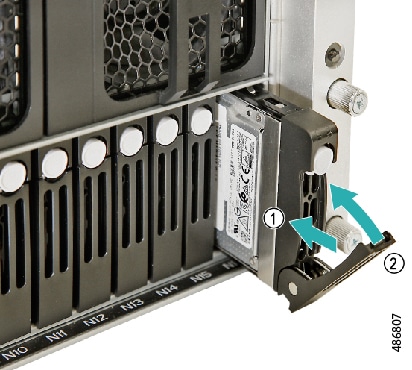
Be careful with your hands and fingers whenever you handle the server, trays, and components! Narrow vertical or horizontal spaces in situations such as, but not limited to, moving the server into or out of the shipping container or equipment rack can cause pinch hazards for your hands and fingers. |
 Warning |
The fully configured server weighs approximately 265 lbs. (120 kg)! Never attempt to lift the server by yourself! Instead, use a lift, scissors jack, or some other device to lift and bear the weight of the server while you are installing or servicing it. If you must lift or handle the server without mechanical assistance, use two or more people to lift and handle server. Always use safe lifting practices when lifting or moving the server. |
Note |
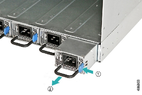
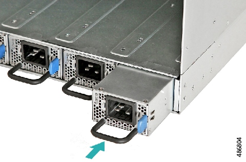
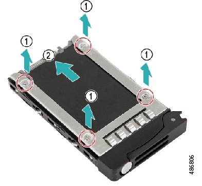
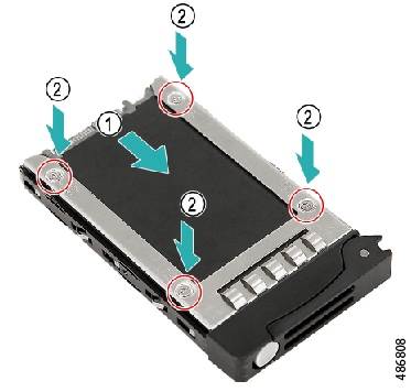
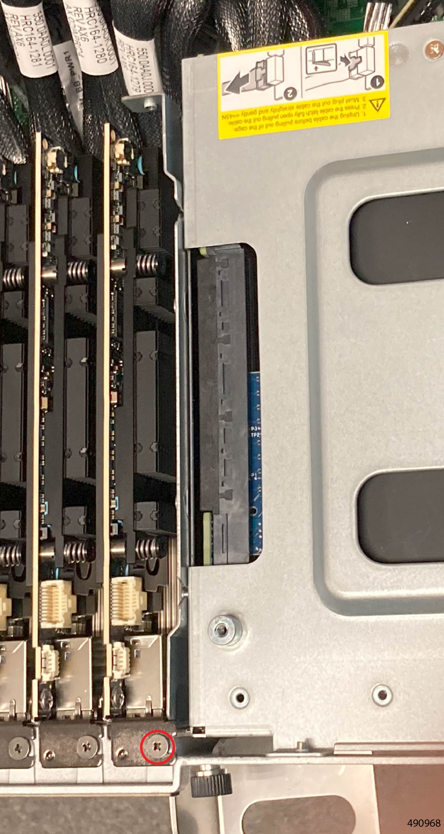
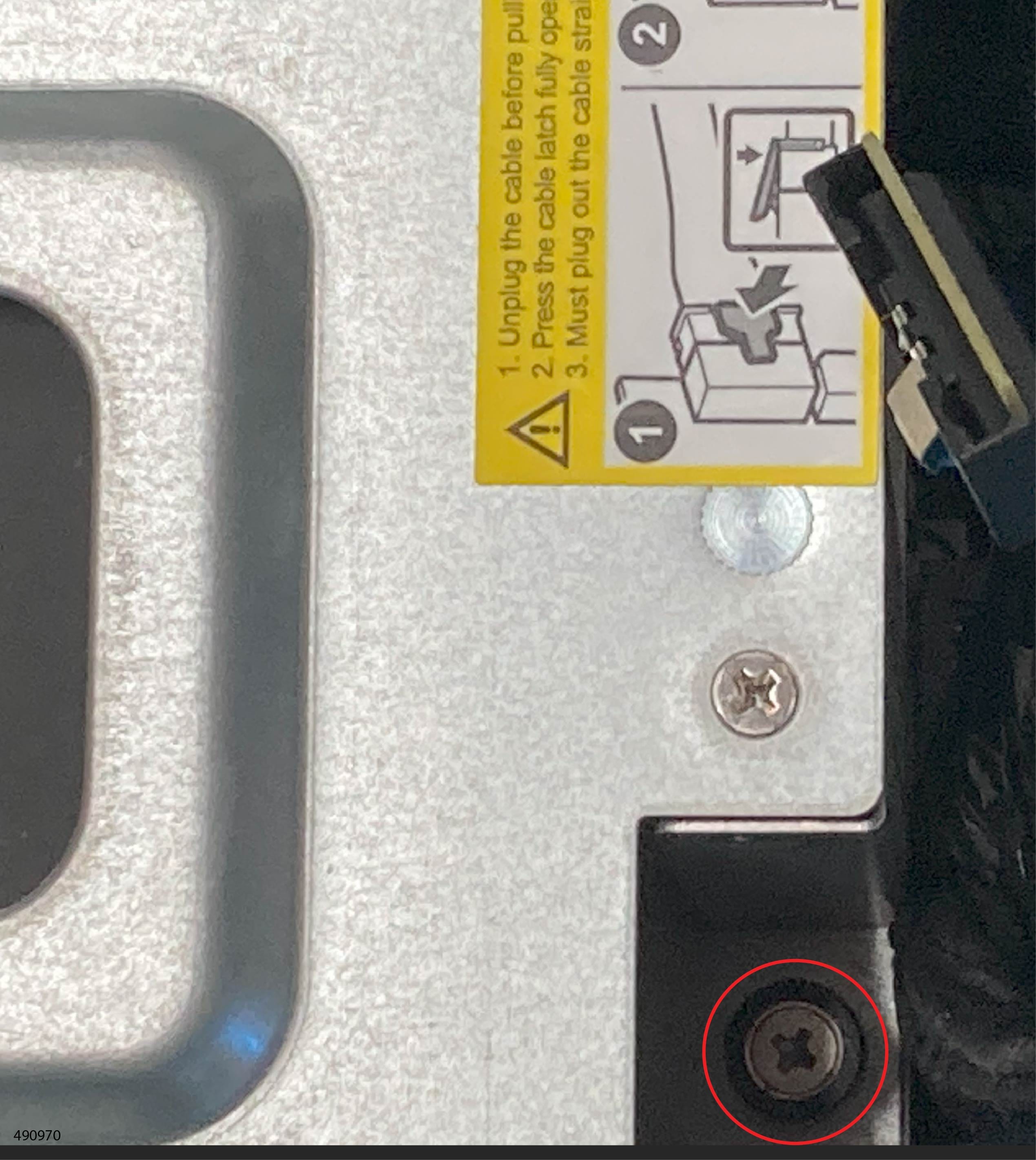
When handling chassis components, wear an ESD strap and handle components, modules, and trays by the edges, or by designated handles when present. |
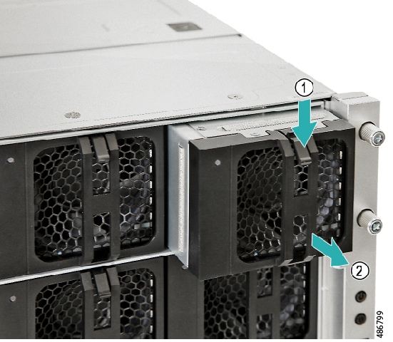
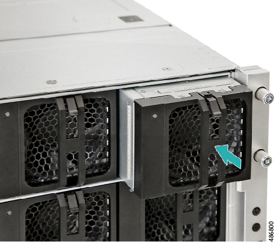
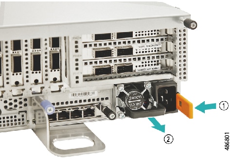
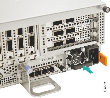
The server is designed as a modular system with subsystems for compute, cooling, and so on. Subsystems are generally arranged in trays, which are field replaceable units (FRUs). However, some components in a subsystem or tray are not individually field-replaceable. The following components are not field replaceable.
-
Mainboard/Motherboard
-
Power distribution board
-
Mid-plane board
-
HIB host interface Board
-
FIO board
-
CEM 8X BB board
-
Left CEM (LCEM) Riser
-
Right CEM (RCEM) Riser
-
Fan extension board
-
Fan interposer board
-
CPUs
-
DIMMs
-
M.2 drives on motherboard
Alignment Features
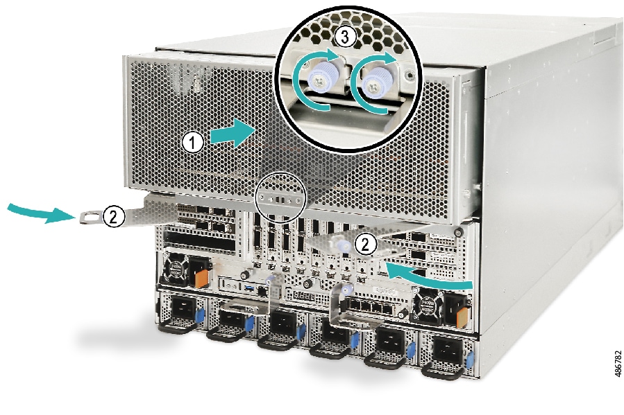
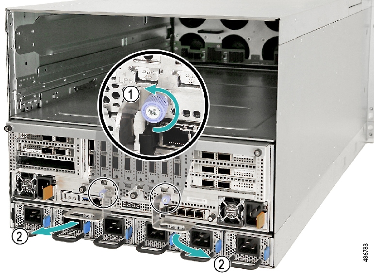
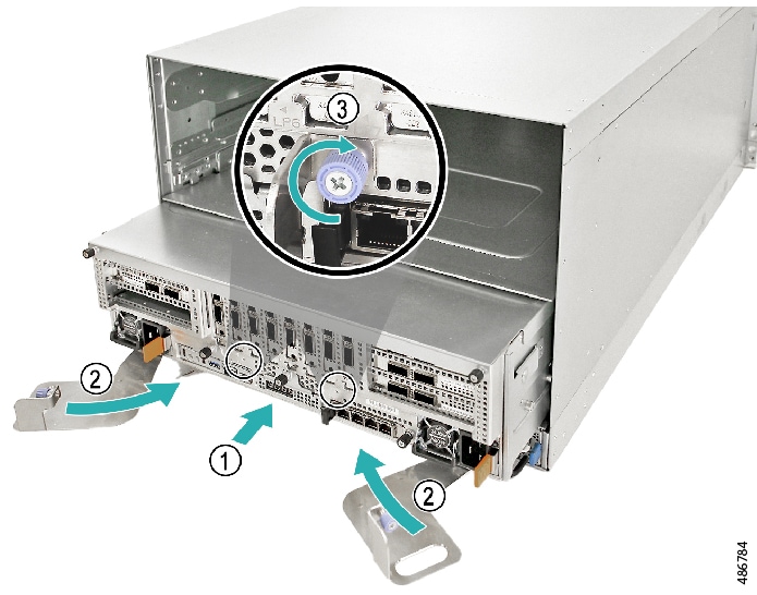
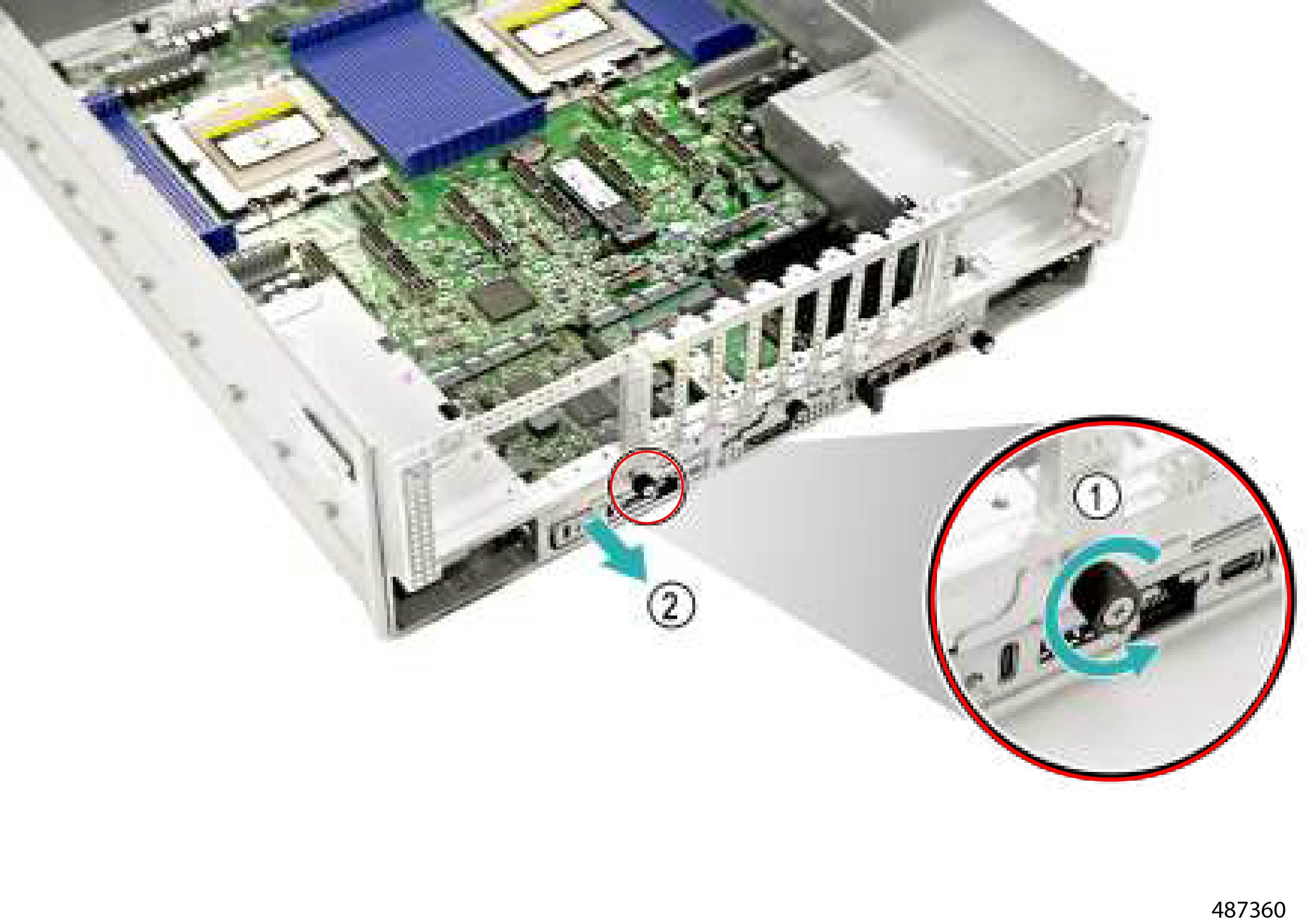
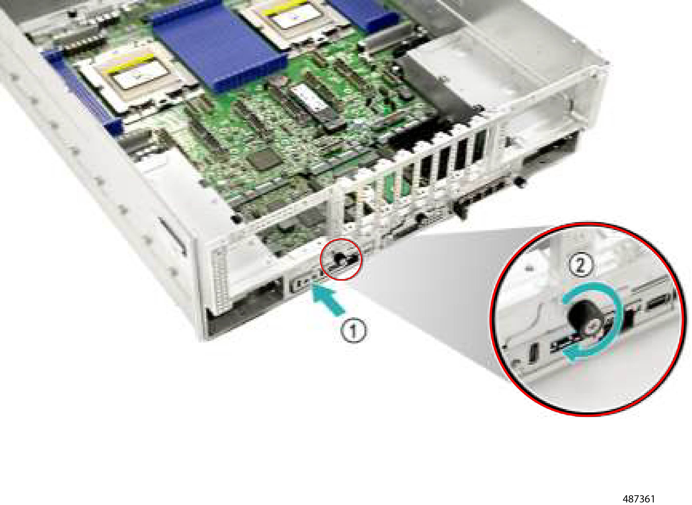
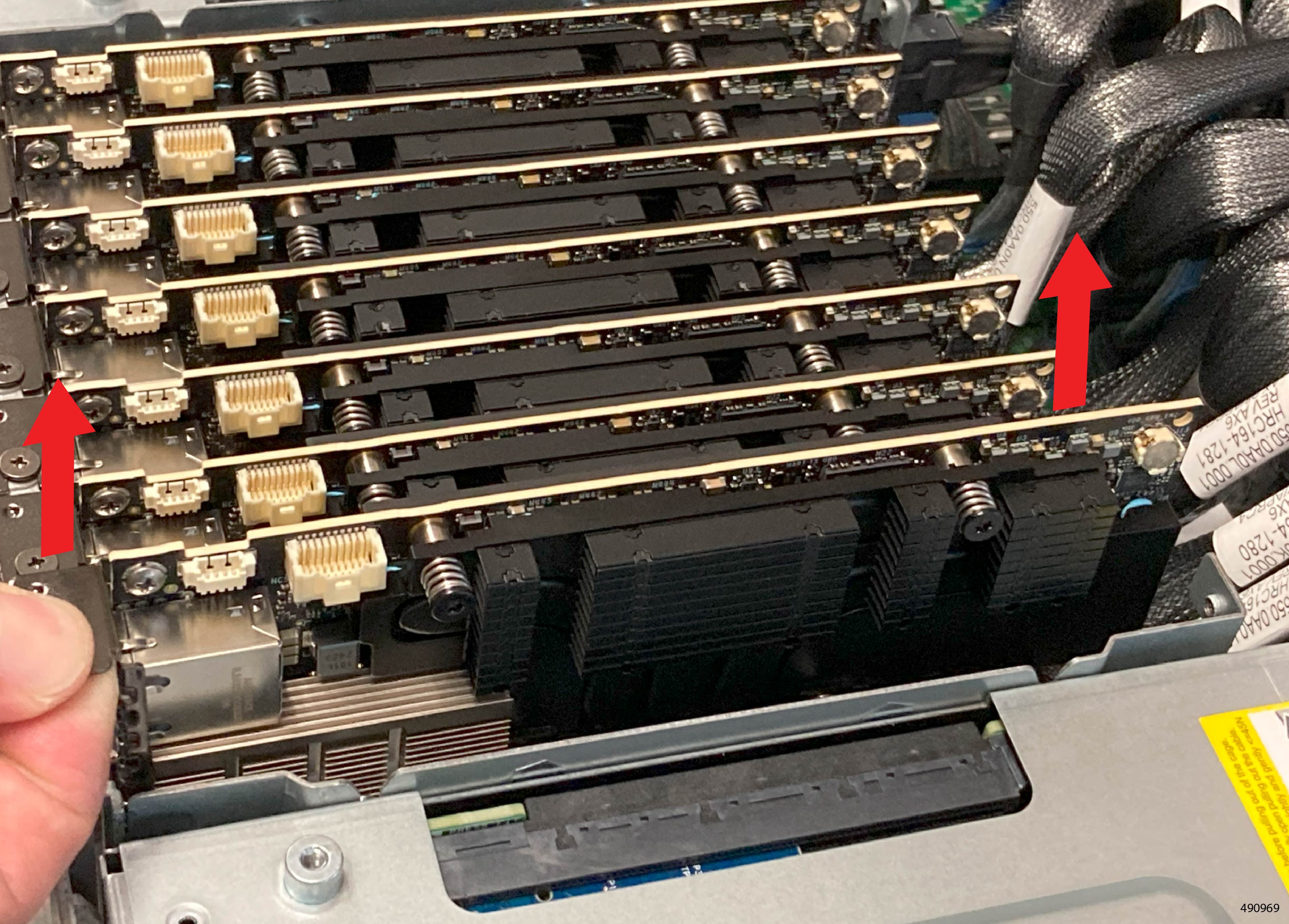
The server has different alignment features that facilitate removing and installing components safely and easily. Being aware of these features will help you replace the field-serviceable components in the server.
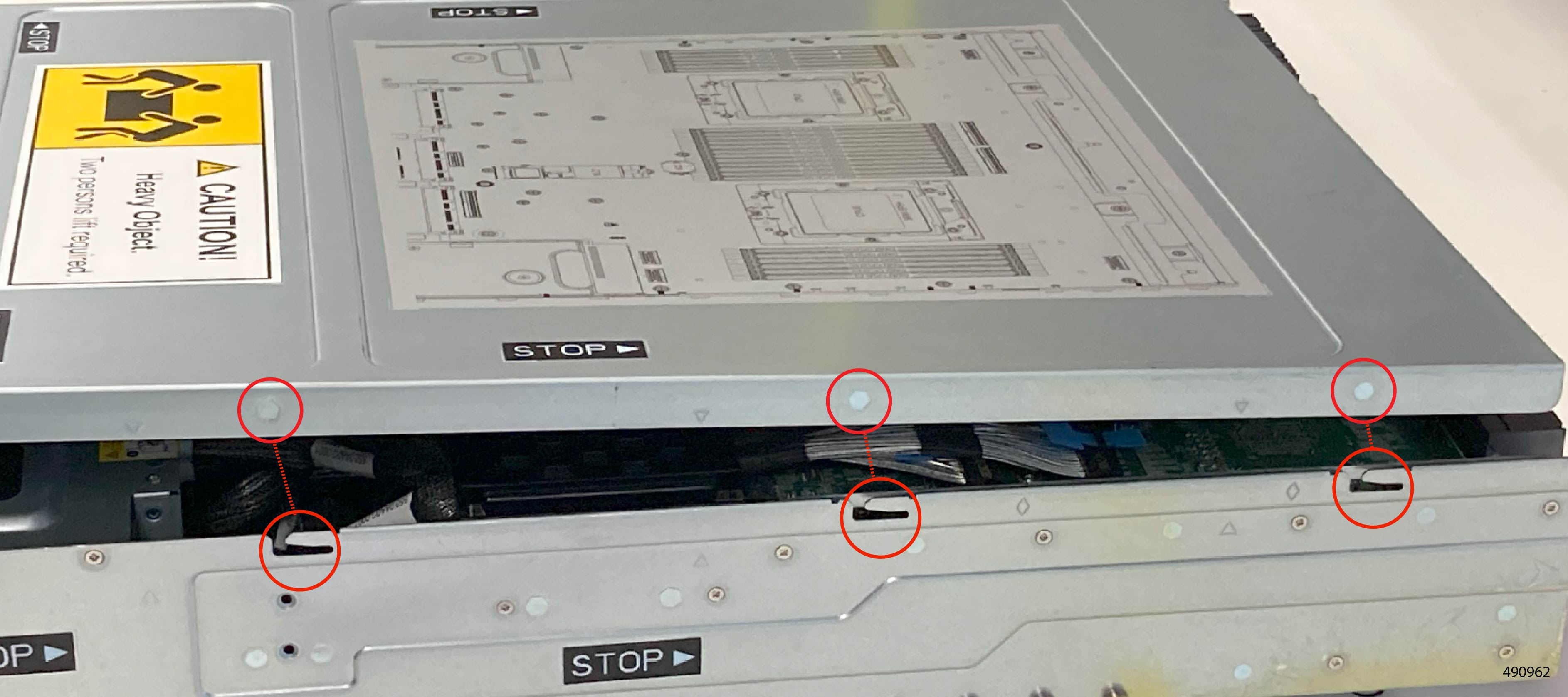
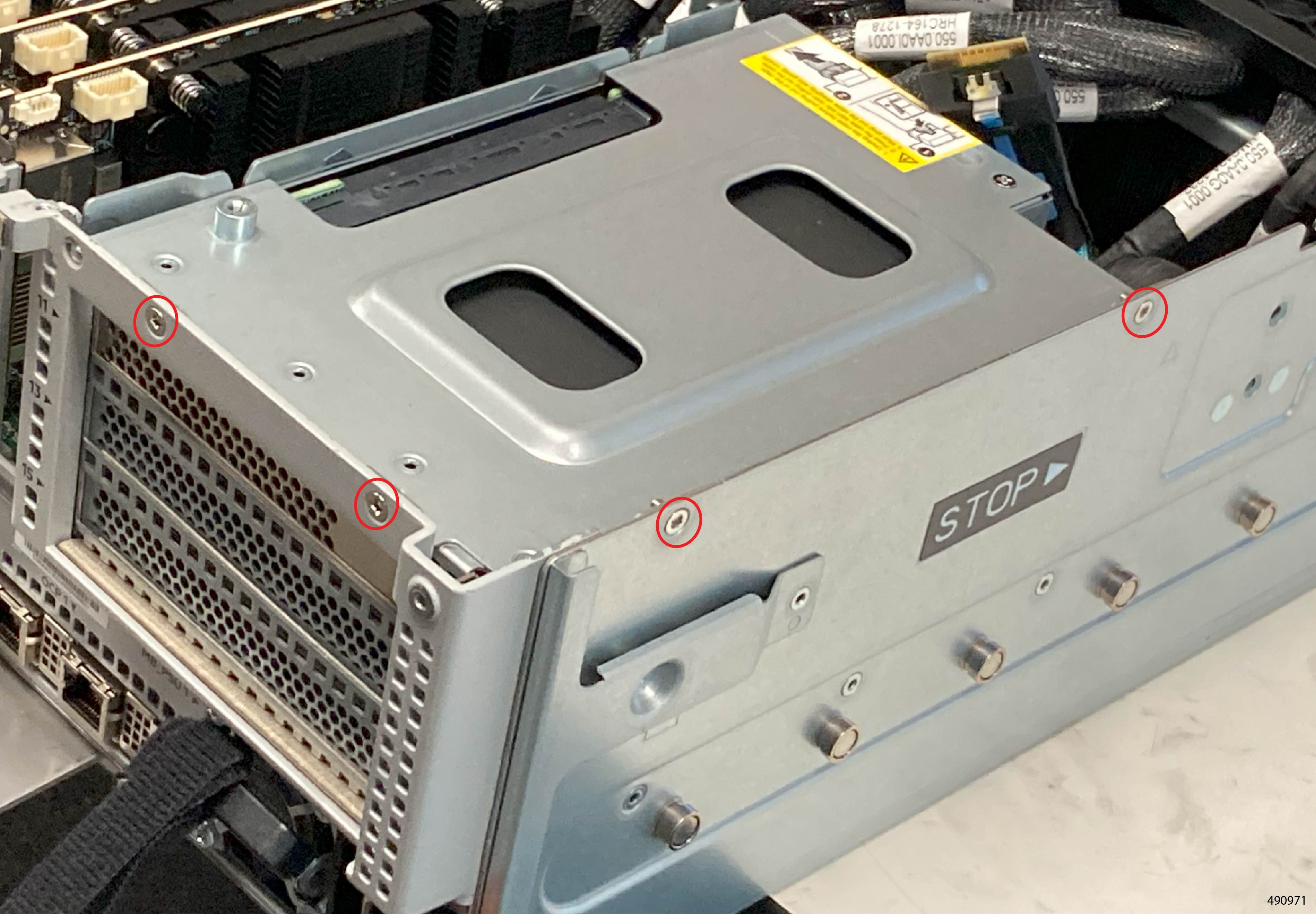
CPU Tray Top Cover Alignment Features
The CPU Tray has grooves and guide pins to help install the top cover of the CPU Tray.
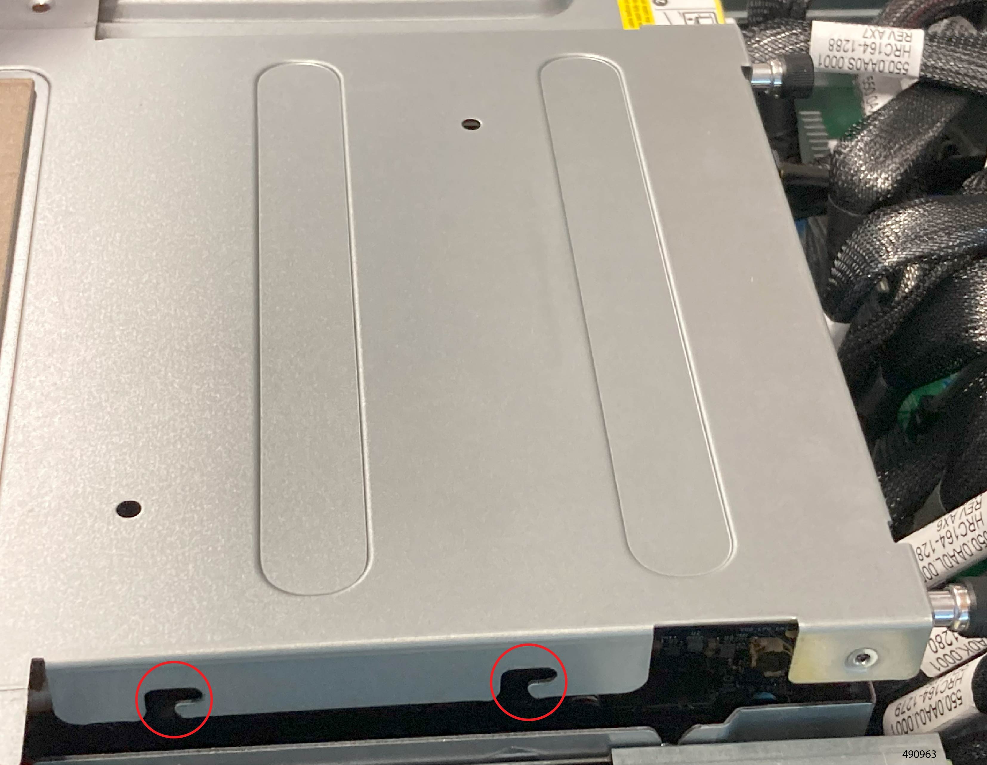
Inner Cover Alignment Features
The inner cover has grooves and catch pins to help align it.
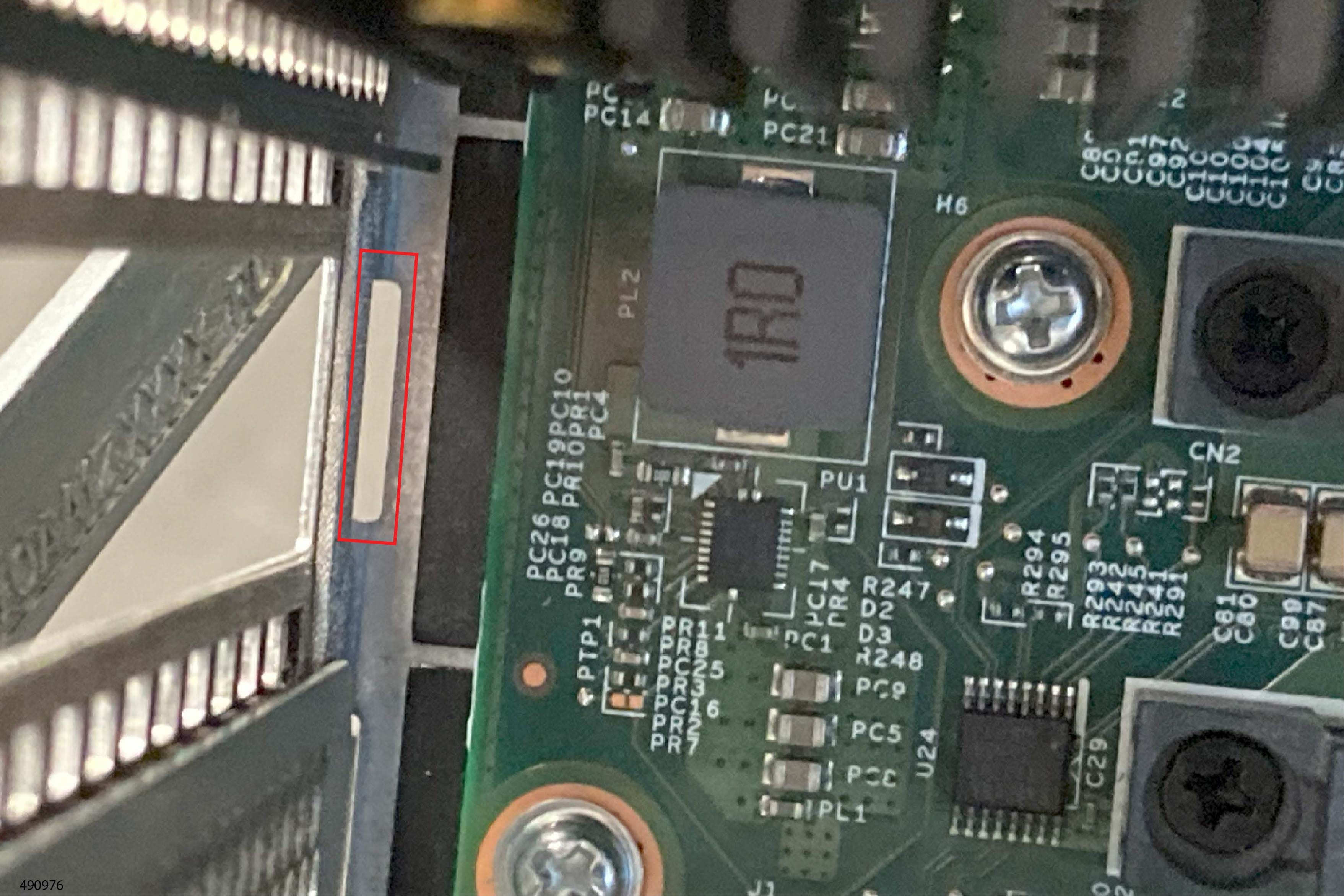
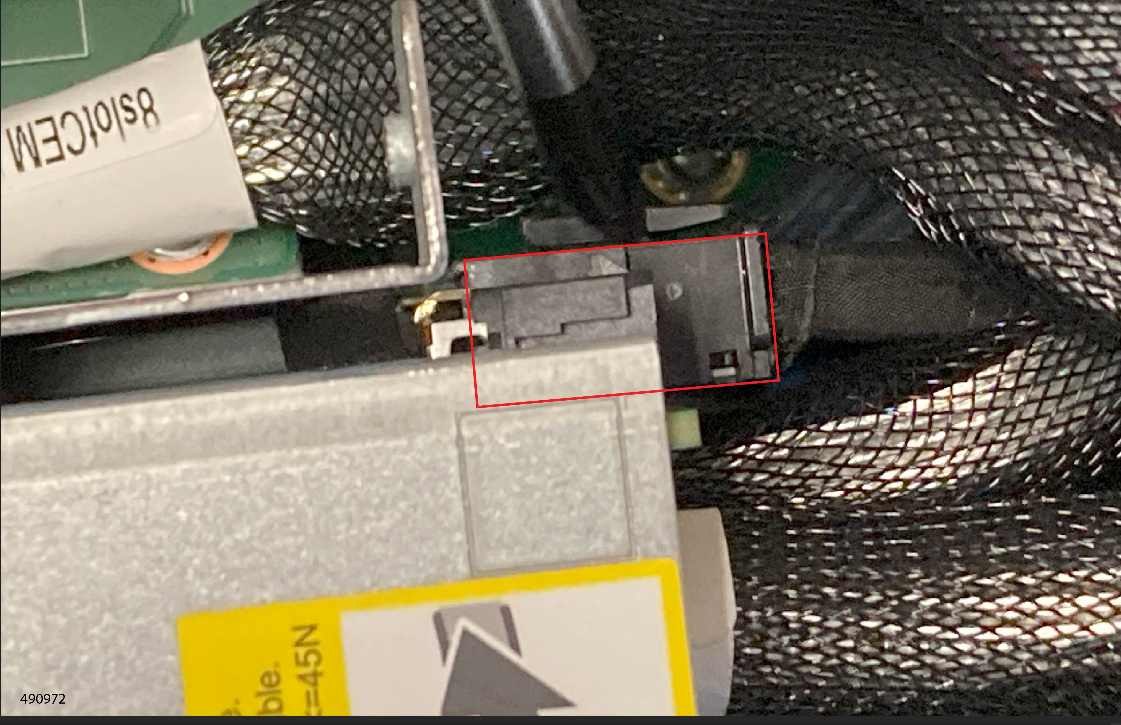
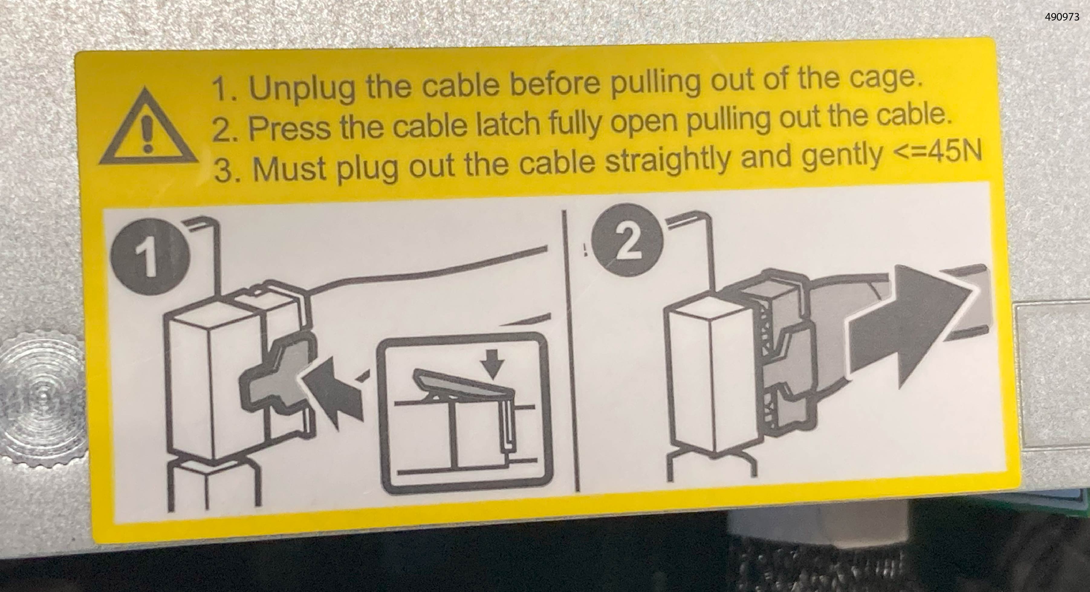
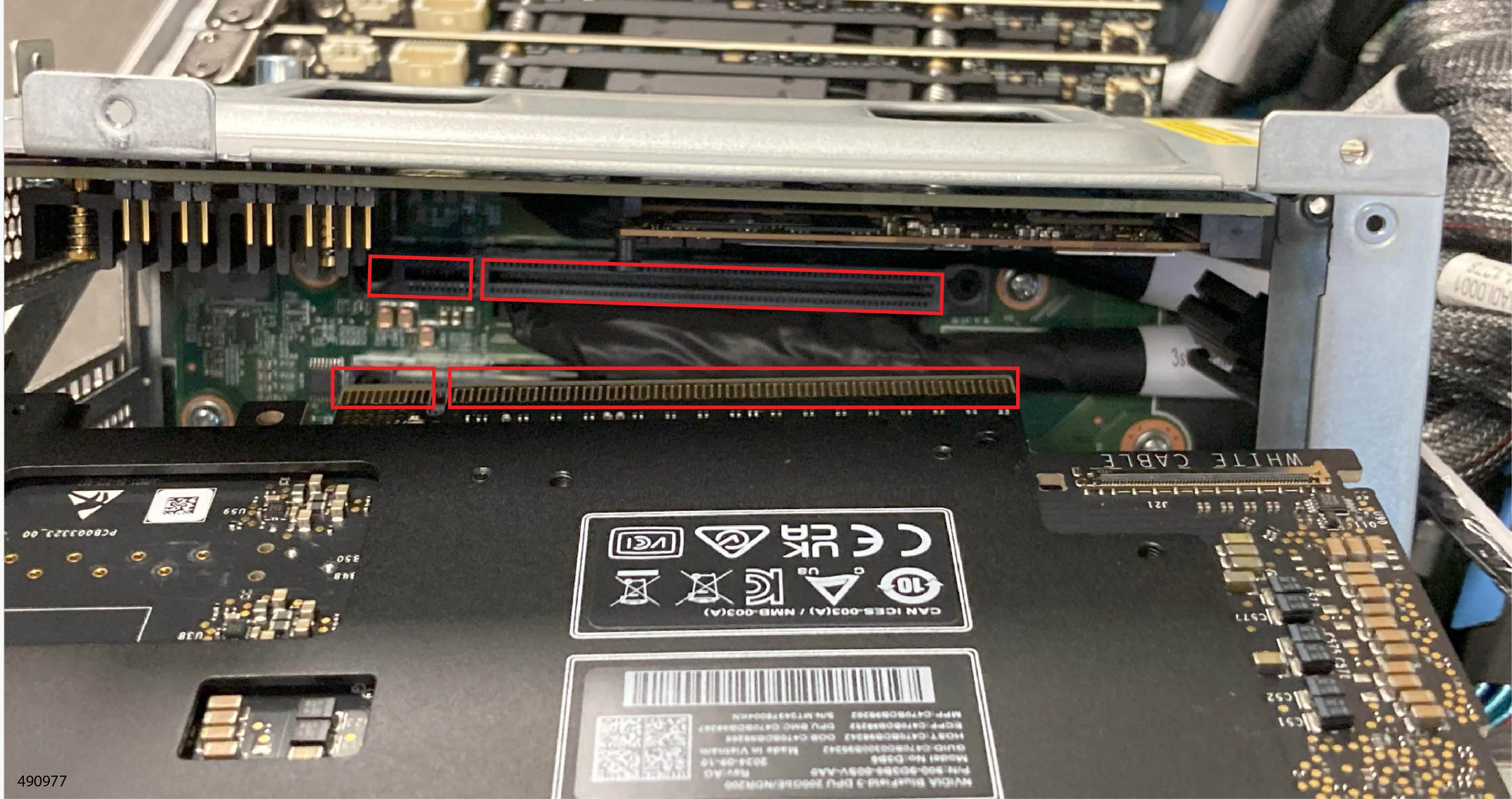
Riser Cage Alignment Features
The interior of the riser cages have notches that meet a tab on the faceplate of the cards that install into them.


 Feedback