Cisco AI POD for Enterprise Training and Fine-Tuning Design Guide
Available Languages
Bias-Free Language
The documentation set for this product strives to use bias-free language. For the purposes of this documentation set, bias-free is defined as language that does not imply discrimination based on age, disability, gender, racial identity, ethnic identity, sexual orientation, socioeconomic status, and intersectionality. Exceptions may be present in the documentation due to language that is hardcoded in the user interfaces of the product software, language used based on RFP documentation, or language that is used by a referenced third-party product. Learn more about how Cisco is using Inclusive Language.
- US/Canada 800-553-2447
- Worldwide Support Phone Numbers
- All Tools
 Feedback
 Feedback
Published: January 2026
About the Cisco Validated Design Program
The Cisco Validated Design (CVD) program consists of systems and solutions designed, tested, and documented to facilitate faster, more reliable, and more predictable customer deployments. For more information, go to: http://www.cisco.com/go/designzone
Executive Summary
Artificial intelligence (AI) and Machine Learning (ML) are fundamentally reshaping organizations, driving investment, innovation, and new opportunities. While many enterprises are launching AI initiatives, ensuring their success presents significant infrastructure and operation challenges.
Cisco AI PODs deliver a comprehensive architecture for building scalable, secure, and right-sized AI/ML infrastructure for enterprises. These full-stack solutions are available in easy-to-order bundles, backed by Cisco Validated Designs (CVDs) and solution-level support through Cisco TAC. By simplifying the design and deployment of AI/ML infrastructure, Cisco AI PODs accelerate AI initiatives, enabling enterprise IT and Lines-of-Business (LOB) teams to confidently deploy AI-ready infrastructure that delivers meaningful business outcomes.
AI POD architecture is designed to adapt to rapidly evolving AI technologies by leveraging the full breadth of Cisco’s Data Center portfolio and strong partnerships with industry leaders. AI PODs are built using Cisco Unified Computing System (UCS) servers with Cisco Intersight, Cisco Nexus networking with Nexus Dashboard, and Splunk Observability Cloud. The design incorporates AI infrastructure best-practices from the Cisco Nexus 9000 platform and serves as a foundational building block of the Cisco Secure AI Factory with NVIDIA. The solution incorporates recommendations from NVIDIA’s Enterprise Reference Architecture and integrates with key storage partners, including NetApp, Pure Storage, and VAST Data.
While this guide currently focuses on core infrastructure, Cisco AI PODs are designed to evolve, enabling future integration with Cisco’s advanced security solutions like Cisco AI Defense, Cisco Hypershield, and Cisco Smart Switches with DPUs to deliver enhanced, distributed protection in AI/ML deployments.
This document is the Cisco AI POD for Enterprise Training and Fine-Tuning Design Guide, detailing the end-to-end solution architecture and design. Upcoming Deployment Guides will provide prescriptive, step-by-step instructions for building and deploying this solution in an enterprise data center. The three Deployment Guides will cover the specific design validated in Cisco IT labs, with a separate guide for each storage partner: NetApp, Pure Storage, and VAST Data.
The complete portfolio of Cisco AI POD CVDs, including this Design Guide and all upcoming Deployment Guides, is available here: Cisco Validated Design Zone for AI-Ready Infrastructure.
Solution Overview
This chapter contains the following:
● Audience
AI/ML is rapidly transforming enterprise organizations, driving a need for reliable, scalable, and secure AI ready infrastructure. This guide provides a comprehensive architecture for an end-to-end, high performance AI infrastructure for model training and fine-tuning in enterprise data centers.
The solution consists of Cisco UCS C-Series (C885A M8 and C845A M8) GPU servers connected to two network fabrics built using Cisco Nexus 9000 Series switches. The AI POD architecture is designed to meet enterprise requirements and features a flexible, modular design that supports deployments starting at 32, 64, or 128 GPU clusters. These clusters serve as foundational building blocks (or Scale Unit Types) that can then be incrementally scaled to support 256, 512, or higher GPU clusters.
This guide is for IT architects, infrastructure engineers, and AI/ML practitioners responsible for designing, building, and managing AI/ML infrastructure in enterprise data centers.
The AI POD designs described in this document are specifically tailored for resource-intensive training and fine-tuning workloads. This guide provides the architectural blueprint and key design considerations necessary to plan a successful AI POD deployment.
This CVD document describes the architecture and design of the Cisco AI POD for AI/ML Training and Fine-tuning. It details the infrastructure building blocks, network fabrics, storage options, and software stacks required to support an AI training cluster running. While the Cisco AI POD architecture can support a range of AI workloads, including inference, the primary focus of this design guide is on enterprise model training and fine-tuning.
Enterprise AI Requirements and Challenges
Enterprises launching AI initiatives and projects need infrastructure that is scalable, secure, and optimized for different AI workloads. This infrastructure must also be designed to minimize operational complexity and ease integration into existing data center environments. However, achieving this poses several challenges that can impact the success of these AI initiatives and delay time-to-value. Organizations must overcome these infrastructure, operations, and security hurdles, all while keeping pace with the rapid evolution of AI technologies.
Some of the critical requirements and challenges that organizations must address include:
● Right-Sizing Infrastructure: Different AI workloads such as training, fine-tuning, and inferencing have different infrastructure requirements. These are influenced by factors such as model size, precision, dataset size, and performance expectations including job completion times and user experience. Enterprises must right-size infrastructure and balance resources across multiple AI projects, typically on shared infrastructure, to avoid over-provisioning or performance issues from under-provisioning.
● Operational Complexity: Building and managing AI infrastructure is inherently complex, requiring new expertise across traditional domains (compute, network, storage) and new ecosystem software and tools. The ramp-up required to support GPU-dense servers, high-performance networking and specialized software and tools, significantly increases the operational burden on IT teams, making integration and efficient management of AI projects a significant challenge.
● Integration into Existing Data Centers: AI infrastructure should ideally integrate with ease into existing enterprise data centers. However, the power, cooling, and specialized networking requirements of AI training clusters make this challenging. While some challenges are unavoidable, strategic design choices can dramatically ease this integration. By leveraging familiar operational models, network design patterns, and software stacks, enterprises can minimize the learning curve and reduce the operational burden on IT teams managing both AI and traditional infrastructure.
● Scaling with Multi-Tenancy: Enterprise AI initiatives often involve multiple teams and lines of business, typically sharing the same infrastructure. This infrastructure must support the various tenant workloads without compromising on performance or reliability. Designing a multi-tenant infrastructure that delivers consistent performance and quality of service (QoS) while maintaining isolation and fairness is critical for AI adoption at scale.
● New Traffic Patterns: AI model training and fine-tuning are highly data-intensive processes that introduce new and demanding traffic patterns within enterprise data centers. This traffic can overwhelm traditional infrastructure, leading to poor AI workload and application performance, such as longer training and fine-tuning job completion times, and higher inference latency.
● Security Vulnerabilities: AI expands the attack surface and introduces new and evolving threat vectors (for example, models, frameworks, applications) that add to enterprise challenges. Protecting sensitive enterprise data and ensuring the integrity of AI models and applications is critical. Key vulnerabilities that an organization may encounter because of this expanded attack surface include:
◦ Compromised datasets used in training/fine-tuning that can skew AI model behavior.
◦ Malicious inputs designed to trick and manipulate model behavior.
◦ Vulnerabilities in underlying AI frameworks or libraries that can be exploited by attackers.
◦ Misconfigured infrastructure components that leave systems exposed to breaches.
● Operational Silos: The complexity of the AI/ML stack, often involving new hardware and software components, can create operational and management silos with fragmented visibility. Lack of end-to-end observability can hinder effective monitoring and troubleshooting, leading to increased operational complexity, delayed problem resolution, and sub-optimal performance.
AI Workloads and Infrastructure Implications
This chapter contains the following:
● Training and Fine-Tuning Workloads
AI workloads have distinct characteristics that place specific demands on the underlying infrastructure. Understanding these differences, particularly between training, fine-tuning, and inferencing, is essential for designing AI infrastructure that is right-sized and optimized for the workload. This guide focuses on training and fine-tuning, which impose the most demanding requirements on compute and networking.
Training and Fine-Tuning Workloads
Training and fine-tuning AI models are typically non-production, offline tasks focused on developing a model from scratch or customizing an existing one. The primary performance metric for these workloads is Job Completion Time (JCT).
While a shorter JCT is desirable, the decision to invest in a larger GPU cluster to reduce JCT is highly organization-specific and depends on the organization’s unique operational and business priorities. For example, one organization might justify a larger cluster to reduce a critical model’s JCT by a few hours, while another might only consider scaling if it cuts JCT by days or weeks. This is especially true for less frequently trained models or where data scientists can work on other tasks while these jobs run.
Justifying additional resources for lower JCT involves a cost-benefit analysis that goes well beyond the direct cost of GPUs. Scaling a GPU cluster significantly impacts the entire supporting infrastructure, requiring more power, cooling, network bandwidth, storage I/O, and physical rack space. These costs, coupled with increased complexity, must be weighed against the business value of faster model iteration and rollout.
To achieve optimal JCTs, the infrastructure must meet the following requirements:
GPU Cluster Size: Training foundational models, such as Large Language Models (LLMs), require massive parallel processing power from large clusters of high-performance GPUs. In contrast, fine-tuning these same models requires significantly fewer resources. GPU requirements vary greatly based on model size, dataset size, and the fine-tuning method used. Table 1 illustrates this difference, comparing the resources used to train Llama 3.1 models against the estimated resources needed for full fine-tuning on different NVIDIA GPU models.
Table 1. Estimated Resource Requirements for Training vs. Full Fine-Tuning
| AI Model |
Model Size (Parameters) |
Training (H100 GPUs) |
Full Fine-Tuning (Estimated Memory) |
Estimated GPU Resources – Full Fine-Tuning (H100 with 80GB of GPU memory) |
Estimated GPU Resources – Full Fine-Tuning (H200 with 141GB of GPU memory) |
| Llama 3.1 |
8B |
32 GPUs |
60GB |
60GB/80GB = ~1 GPU |
60GB/141GB = ~1GPU |
| Llama 3.1 |
70B |
256+ GPUs |
500GB |
500GB/80GB = ~7 GPUs |
500GB/141GB = ~4 GPUs |
| Llama 3.1 |
16,000 GPUs |
3.25TB |
3.25TB/80GB = ~40 GPUs |
3.25TB/141GB = ~24 GPUs |
Source: https://arxiv.org/pdf/2407.21783 | https://huggingface.co/blog/llama31#training-memory-requirements
Table 1 shows that the GPU requirements for fine-tuning are orders of magnitude lower than those of training. These requirements can be further reduced by using more performant GPUs (for example, H200 instead of H100). The choice of fine-tuning method, from 32-bit full fine-tuning to 4-bit Parameter Efficient Fine-Tuning (PEFT), also has a significant impact on GPU requirements, as shown in Table 2.
Table 2. Estimated Resource Requirements for Fine-Tuning a Llama 3.1 70B model using H200 SXM GPUs
| AI Workload |
Model Size |
Precision |
Estimated Memory Requirement |
Estimated GPU Resources |
| Full Fine-Tuning |
70B |
32-bit |
1200GB |
1200GB/141GB = ~9 GPUs |
| Full Fine-Tuning |
70B |
16-bit |
600GB |
600GB/141GB = ~5 GPUs |
| PEFT – LoRA/Badam/… |
70B |
16-bit |
160GB |
160GB/141GB = ~2 GPUs |
| PEFT - QLoRA |
70B |
8-bit |
80GB |
80GB/141GB = ~1 GPU |
| PEFT - QLoRA |
70B |
4-bit |
48GB |
48GB/141GB = ~1 GPU |
Source: https://github.com/hiyouga/LLaMA-Factory?tab=readme-ov-file#hardware-requirement
Note: In the provided scenarios, the actual memory requirements and GPU resources required can vary depending on factors such as dataset size, optimizations, and model architecture.
Key Takeaway: A typical enterprise fine-tuning workload for a large model requires a cluster of 32 to 64 GPUs. To support multiple similarly-sized workloads concurrently (for different projects), the GPU cluster size must scale accordingly, yet it remains significantly smaller than the thousands of GPUs required to train a foundational model from scratch.
Stringent Network Requirements: Training and fine-tuning rely on critical GPU-to-GPU communication. These workloads involve frequent synchronization and collective operations to exchange data between GPUs allocated to the workload. This requires a network fabric that provides:
● High Throughput: Supports concurrent high-bandwidth data flows between GPUs.
● Low End-to-End Latency: Minimizes data exchange delays in which directly impact JCT.
● Lossless: Packet drops can force training jobs to restart, severely impacting JCT. Technologies like Priority Flow Control (PFC) and Explicit Congestion Notification (ECN) are essential to prevent this.
● Low Jitter: Mitigates microsecond buffer overruns and transient congestion caused by synchronous, bursty GPU operations.
● Efficient Load Balancing: Training workloads often have low entropy, which can lead to inefficient link utilization with traditional Equal-Cost Multi-Path (ECMP. AI/ML networks require advanced load-balancing strategies to maximize link utilization and minimize congestion.
High Availability, Security, and Operations: While important, these aspects are generally less critical for pre-production training and fine-tuning environments when compared to production inferencing, where real-time user interaction and continuous service are paramount.
Workload Management: Efficient scheduling and orchestration of workloads and GPU resources are essential for managing complex training and fine-tuning jobs.
Unlike training, inferencing workloads process live, production traffic, often in real-time. Performance is measured by latency and throughput metrics, which are influenced the number of concurrent users, input/output token sizes, and batch sizes.
Key metrics for inferencing include:
● Time-to-First Token (TTFT): Measures the interval between a user prompt to receiving and the first output token. This is critical for perceived responsiveness, as it represents a user’s wait time before seeing the start of a response.
● End-to-End Request Latency: Measures the total time to receive a complete response. This metric represents the user's total wait time for an answer; a function of TTFT and the generation time for the remaining tokens.
● Time per Output Token (TPOT) or Inter-Token Latency: Measures the average time between subsequent tokens after the first.
● Requests per Second: Measures the volume of user requests that the system successfully completed per second.
● Tokens per Second or Throughput: Measures the total system-wide output tokens per second across all concurrent requests.
Inferencing infrastructure typically requires:
● Smaller GPU clusters: Fewer GPUs compared to training and fine-tuning. Even large models that require multiple GPUs are typically contained within a single server.
● Less stringent network requirements: Can utilize existing 100/200 GbE data center fabrics.
● High Availability, Security, and Observability: Critical for production inferencing, similar to other mission-critical applications running in enterprise data centers.
It is important to note that inferencing landscape is evolving rapidly. New agentic AI workloads, where models engage in multi-step reasoning, use tools, and interact with other AI agents or systems, will likely impose new demands on the AI infrastructure, including more complex communication patterns, higher sustained data rates, and lower latency requirements.
While inferencing is critical for enterprises, its architecture and designs are outside the scope of this guide. See Cisco Validated Design Zone for AI-Ready Infrastructure for Inferencing AI POD CVDs.
Cisco AI PODs: A Complete Solution for Enterprise AI
This chapter contains the following:
● How AI PODs Address Enterprise AI Challenges
Cisco AI PODs provide a validated, integrated architecture that meets the stringent requirements of AI workloads. This section introduces the AI POD architecture and outlines its role as a foundational infrastructure stack for enterprise AI deployments.
Cisco AI PODs are modular, full-stack infrastructure solutions designed to accelerate a wide range of AI initiatives and use cases in enterprise organizations. Cisco AI PODs support various AI workloads—including training, fine-tuning, inferencing—enabling enterprises to confidently deploy and operate infrastructure that meets diverse AI requirements.
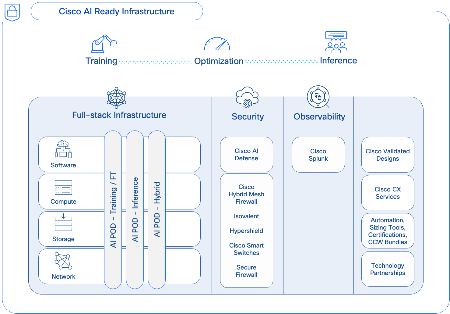
AI PODs are a core component of Cisco’s AI strategy (Figure 1) for delivering secure, AI-ready infrastructure for enterprise organizations. They can be deployed as dedicated, fit-to-purpose stacks for specific AI workloads (for example, Training) or as hybrid stacks, supporting multiple AI workloads (for example, Training and Inferencing). This gives enterprises the flexibility to support multiple AI projects and workloads across the organization.
Cisco AI PODs simplify the path to AI by providing fully integrated, easy-to-order bundles. Backed by CVDs and Cisco TAC support, AI PODs enable Enterprise IT and LOB teams to quickly deploy full-stack, AI-ready infrastructure without compromising on flexibility or choice.
How AI PODs Address Enterprise AI Challenges
Cisco AI PODs provide a comprehensive, full-stack architecture that addresses the infrastructure and operational challenges of enterprise AI. By delivering a high-performance, right-sized, and scalable solution, AI PODs adapt to evolving needs while simplifying design, deployment, and management.
● Right-sized Infrastructure for Enterprise AI Workloads: Enterprise AI applications require models spanning from classic predictive ML models to Small Language Models (SLMs) and generative LLMs with billions of parameters. A single application may also use a combination of models depending on the use case. Consequently, as AI adoption grows, organizations will need to support dozens, and eventually hundreds, of diverse models.
Since most enterprises focus on customizing pre-trained foundational models using techniques like fine-tuning and Retrieval-Augmented Generation (RAG), these tasks represent the most common AI workloads in enterprise deployments. Though resource-intensive, these workloads require significantly fewer GPUs than training from scratch, as illustrated in Tables 1 and 2. AI PODs meet this need with modular Scale Unit Types (32, 64, or 128 GPUs) to ensure efficient resource utilization without costly over-provisioning. This modular approach allows enterprises to select an optimal starting cluster size for their AI initiatives and then scale precisely and incrementally as their needs evolve.
● Optimized for AI Workloads: AI PODs feature non-blocking, lossless, high-bandwidth, and low-latency network designs engineered to handle the data-intensive traffic patterns of model training and fine-tuning. This eliminates network bottlenecks, and ensures optimal JCT.
● Multi-tenancy: To support concurrent workloads from multiple projects and LOBs, the AI POD design uses MP-BGP VXLAN EVPN to create secure, isolated environments for each tenant. VXLAN provides data plane isolation by encapsulating each tenant’s traffic into a unique virtual network (L2 or L3), while MP-BGP ensures control plane isolation through Virtual Routing and Forwarding (VRF) instances.
● Operational Ease and Consistency, at Scale: Modular building blocks and scale-out spine-leaf designs in the AI POD architecture, enable enterprises to incrementally expand their infrastructure without complex redesigns, while maintaining design and operational consistency at scale.
● Simplified Data Center Integration: AI PODs simplify integration by using familiar technologies, tools, and design patterns commonly seen in enterprise data centers. The AI POD design leverages familiar management tools like Cisco Intersight and Nexus Dashboard, along with established network designs like VXLAN EVPN fabrics and Spine-Leaf topologies. This alignment provides operational consistency, simplifies adoption, and reduces the learning curve for IT teams managing both AI and traditional infrastructure.
● Enhanced Observability: Powered by the Splunk Observability Cloud, AI PODs deliver end-to-end visibility across the entire AI/ML stack. This integrated observability helps to eliminate operational silos, streamline monitoring, and accelerate troubleshooting and performance optimization.
● Strengthening Security Posture (Future Integration): While the current focus is on the core compute, networking and storage infrastructure, AI PODs will evolve and integrate with advanced Cisco security solutions (for example, AI Defense, Hypershield) that protect against new threat vectors emerging in AI/ML deployments.
When planning an AI infrastructure for training and fine-tuning, a basic decision is determining the optimal size of your AI training cluster. Right-sizing this cluster requires a clear understanding of workload needs and translating these requirements into GPU resources necessary to meet target Job Completion Times.
Note: In this context, a workload refers to the specific model being trained or fine-tuned, and not the broader AI use case.
Key Factors for Sizing Your GPU Cluster
The size of your GPU cluster is determined by two main factors:
● Single Largest Workload: This is the single model (or workload) that requires the most GPU resources for one training or fine-tuning job. It sets the baseline for the minimal number of GPUs required per workload and the optimal connectivity for the GPUs assigned to this job.
● Concurrent Workload Requirements: This is the number of similar or smaller-sized workloads that need to run concurrently on the cluster. This will determine the total cluster capacity, at peak load, across all projects and tenants.
In an enterprise setting, the concurrent workloads could be from multiple projects, LOBs or even single use cases that involve several models. What matters ultimately is the total number of models (or workloads) that must be hosted on this infrastructure, as this directly impacts the cluster size and the infrastructure required to support it.
For sizing the cluster, the largest workload is important for two reasons. First, it defines the minimal GPU resources required to run the most demanding workload in your environment, which can then be used to determine the overall cluster capacity based on the number of concurrent workloads this infrastructure needs to support. Secondly, it directly influences the connectivity design for GPU-to-GPU communication. All GPUs allocated to the same workload should ideally have the most optimal, non-blocking connectivity, which has a bearing on how the GPU nodes are connected to the fabric. For more information, see the Backend Fabric Design (East-West) section.
Approaches to Sizing
Estimating the largest workload can be challenging, as users often request the latest, largest models to future-proof their projects, making it difficult for IT teams to right-size the infrastructure.
Given this, two practical approaches that enterprises could take are:
● For workloads migrating to on-prem from the cloud, use historical resource consumption as a starting point.
● For workloads without historical data, use a relatively large, current LLM as your reference workload to model resource requirements.
As previously stated, customizing an LLM is often the largest, most-demanding workload for an enterprise. By estimating the GPU resources required for this single task and then multiplying it by the expected number of concurrent workloads (across all tenants), you can calculate the total GPU resources required and begin designing the complete AI infrastructure.
Architecture
This chapter contains the following:
● Key Infrastructure Building Blocks
● Dual Fabrics: Backend and Frontend Networks
● Modular and Scalable Design: Scale Units and Scale Unit Types
The Cisco AI POD is a modular architecture designed to provide a scalable and performant infrastructure for distributed AI training and fine-tuning. This section provides a high-level overview of the end-to-end solution and the core hardware and software building blocks that make up the architecture.
Figure 2 illustrates the high-level architecture of the AI POD.
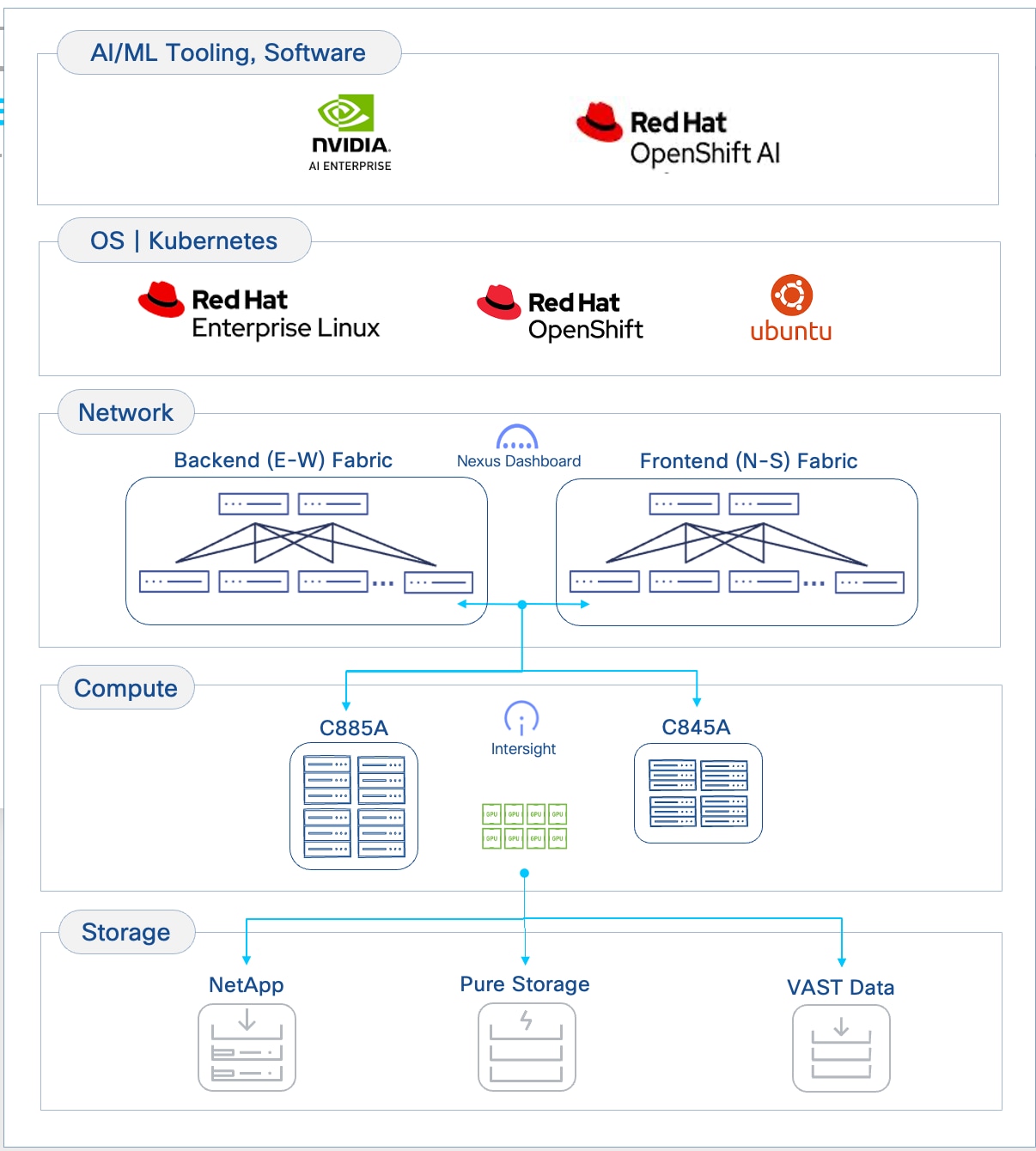
The design takes a modular, building blocks approach, integrating compute (CPU, GPU), networking, storage, operating system (OS)/Kubernetes (K8s) platform, and AI software components. This delivers an AI-ready infrastructure that enterprises can deploy to support a range of AI initiatives and scale as needed with consistency, simplicity and operational ease.
Key Infrastructure Building Blocks
Cisco provides a comprehensive portfolio of products and solutions optimized for the full-breadth of the AI/ML lifecycle—from training to inferencing to hybrid deployments. Cisco AI PODs deliver foundational AI/ML infrastructure stacks designed to address an organization’s current and future AI needs. The AI POD solutions will continue to evolve, incorporating capabilities from Cisco’s extensive portfolio across compute, network, security, and observability to deliver a robust AI infrastructure stack for enterprise organizations.
The Cisco AI POD architecture is a fully integrated, full-stack solution built from the following core components:
● Compute: Purpose-built Cisco UCS AI servers provide the GPU-dense compute power necessary for large-scale distributed training and fine-tuning.
● Network: The Cisco Nexus 9000 series provides a high-bandwidth, low-latency network fabric, managed by Cisco Nexus Dashboard, to ensure lossless communication for both backend (East-West) and frontend (North-South) traffic.
● Storage: Validated enterprise storage from industry-leading partners (such as NetApp, Pure Storage, and VAST) provides the high-performance, scalable, and reliable data access essential for data-intensive AI workloads.
● Software Stack: A comprehensive software stack combines the operating system, workload orchestration (K8s or Simple Linux Utility for Resource Management (SLURM)), and essential GPU libraries from NVIDIA to run and manage AI workloads efficiently.
● Management: A unified management framework uses a dedicated management cluster, running on separate Cisco UCS servers, to host the control planes for the software stack. This is complemented by Cisco Nexus Dashboard and Cisco Intersight, which provide centralized management and automation for the physical network and compute infrastructure.
● Observability: End-to-end observability, powered by Splunk, delivers full-stack visibility into the health and performance of the entire AI infrastructure, from hardware to applications.
The following sections provide a detailed look at each of these building blocks.
Compute: Cisco UCS GPU Servers
The core compute platforms in this Cisco AI POD architecture are the purpose-built Cisco UCS GPU servers. These servers are designed for large-scale distributed training and fine-tuning, offering distinct options to match different deployment needs:
● Cisco UCS C885A M8 server is a fixed-configuration, NVIDIA SXM or AMD OAM based 8-GPU system optimized for maximum performance and density.
● Cisco UCS C845A M8 server is a flexible platform supporting 2, 4, 6, or 8 PCIe GPUs, allowing for modular scalability.
Both platforms support multiple NVIDIA and AMD GPU models with high-speed, internal GPU-to-GPU connectivity. The choice between these models will depend on the specific AI workload requirements and performance targets.
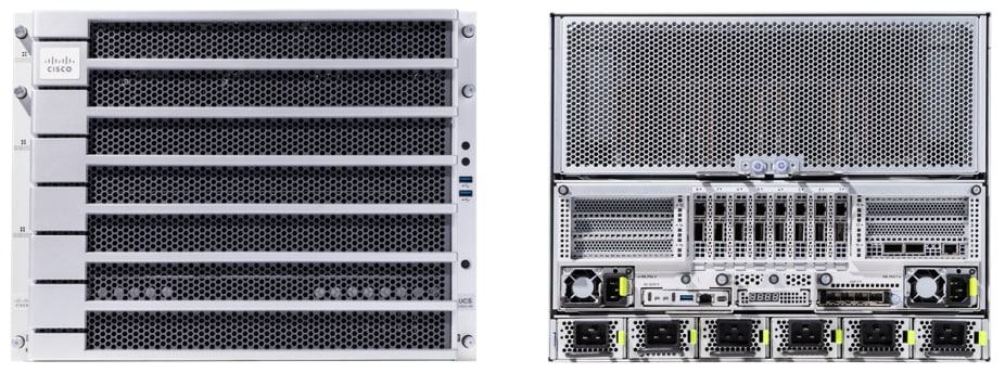
Cisco UCS C885A M8 Rack Server
AI model training and fine-tuning often involves extensive matrix multiplications and parallel computations that require high-performance GPUs with high-bandwidth connectivity, both within and across systems. The Cisco UCS C885A M8 is a high-performance, 8-RU, 8-GPU (AMD OAM or NVIDIA SXM-based) rack server designed to provide the GPU density and high-speed interconnects necessary for these workloads.
Cisco UCS C885A is based on NVIDIA’s HGX architecture, specifically the HGX 2-8-9-400 architecture using 2 CPUs, 8 NVIDIA GPUs, 9 NVIDIA NICs, and 400Gbps of bandwidth per GPU to the backend (East-West) fabric.
Note: The Cisco UCS C885A supports up to two NICs to connect to the frontend fabric.
The Cisco UCS C885A M8 features two 4th or 5th Gen AMD EPYC CPUs and up to 24 DDR5 RDIMMs (up to 6,400 MT/s) to provide the high core count and memory bandwidth needed to manage the operating system and support these AI workloads.
Dedicated, High-Speed GPU-to-GPU Interconnects
Distributed training and fine-tuning typically involves cycles of computations, followed by collective operations to synchronize states that require all or groups of GPUs to exchange data with each other, often at the same time or synchronously and using up all available bandwidth on the links. For more info on the collective operations used in a training and fine-tuning environment, see NVIDIA Collective Communications Library (NCCL) Overview and AMD’s ROCm Communication Collectives Library (RCCL) documentation.
For performant AI training and fine-tuning jobs, the dedicated high-speed GPU-to-GPU interconnects within the system will provide a low-latency, high-bandwidth fabric for efficient data and gradient synchronization across GPUs, directly impacting the speed, efficiency and scaling training jobs. The high-speed interconnects within a Cisco UCS C885A are:
● NVIDIA NVLink with NVSwitches: On a system with NVIDIA GPUs, the eight GPUs are interconnected using NVLink and NVSwitches, enabling 900 GB/s of bidirectional bandwidth between any pair of GPUs within the server.
● AMD Infinity Fabric: On a system with AMD GPUs, the eight GPUs are interconnected using AMD’s Infinity Fabric, enabling over 128 GB/s of bidirectional bandwidth using a full-mesh topology for direct GPU-to-GPU communication.
The direct GPU-to-GPU communication enabled by the dedicated interconnects bypasses the CPU and system memory for significantly faster data exchange and improved job completion times.
GPU Options
Each Cisco UCS C885A M8 server offers a fixed configuration of 8 GPUs – either NVIDIA (HGX H200) or AMD (MI300X, MI350X OAM) GPUs. These GPUs are necessary for the demanding AI workloads such as training and fine-tuning of Large Language Models (LLMs) as well as distributed inferencing with large parameter (70B+) models.
For up-to-date information on the GPU models available on the Cisco UCS C885A, see Appendix A - References.
External Network Connectivity for Scaling Training and Fine-Tuning Clusters
Unlike inferencing, AI training and fine-tuning often extends beyond a single server, requiring clusters of dense 8-GPU servers, anywhere from 4, 8, 16 nodes to as high as 64, 128 nodes in enterprise deployments. To facilitate this scaling, Cisco UCS C885A M8 servers provides the following network interface options:
● NICs for connectivity to Backend(BE) / East-West(E-W) Fabric: Each Cisco UCS C885A server is equipped with eight PCIe Gen5 x16 HHHL slots and eight dedicated (1x400G) NICs (for example, NVIDIA BlueField-3 B3140H SuperNIC or ConnectX-7 or Pensando Pollara 400) for connecting to the BE network fabric. The NICs provide high-bandwidth, low-latency GPU Direct RDMA communication between GPUs residing on different C885A M8 servers connected to the same backend fabric.
● NICs for connectivity to Frontend(FE) / North-South(N-S) Fabric: Each Cisco UCS C885A server is equipped with five PCIe Gen5 x16 FHHL slots, with four available for use as FE/N-S NICs to connect to the frontend fabric. These NICs can be 2 x NVIDIA BlueField-3 B3220 or B3240 DPUs or 4 x ConnectX-7 NICs. The FE fabric can be a dedicated fabric or an existing data center fabric and provide connectivity for AI workload management and orchestration components, access to high-speed storage access, network services, and when used for inferencing, it will also be used for inferencing requests from users and applications to models hosted on the C885A.
Note: Currently, the BlueField-3 B3240 FE NIC is only available for Cisco Hyperfabric AI deployments.
The Cisco UCS C885A M8 server use PCIe Gen5 for high-speed connectivity between GPUs and NICs, ensuring maximum data throughput.
Storage for Data-Intensive Workloads
AI training and fine-tuning are inherently data-intensive processes, requiring access to large datasets. The C885A M8 platform supports the following storage options to meet these demands:
● Local High-Speed NVMe: Each C885A M8 server can be configured with up to 16 PCIe Gen5 x4 2.5” U.2 NVMe SSDs, providing high-speed local storage. This capacity is beneficial for caching frequently accessed training data, storing intermediate results, or for checkpointing model parameters during long training runs, thereby reducing I/O latency and improving GPU utilization. Also, up to 2X PCIe3 x4 960GB M.2 NVMe drives are also included for booting the operating system.
● External Storage Integration: For access to shared datasets, the platform supports standard IP-based storage protocols such as NFS and object storage. In AI POD deployments, a dedicated storage NIC can be deployed to ensure high-bandwidth data transfer rates between the compute nodes and the external storage systems, preventing storage I/O from becoming a bottleneck to training performance. GPUDirect RDMA is also supported on the frontend NICs for high-speed, low latency connectivity between GPUs and external storage systems.
Building Block for Scale Units
The Cisco UCS C885A M8 server is a foundational compute option for AI POD's modular Scale Units that will be discussed in an upcoming section. Multiple Cisco UCS C885A servers are combined with specific models of Cisco Cloud Scale (CS) and Silicon One (S1) Nexus leaf switches to form distinct Scale Unit Types that enables customers to start with a cluster that meets their current needs (for example, 32, 64 or 128 GPU cluster), but that can scale to higher clusters (for example, 128, 256 or 512 GPUs) as their needs evolve, in a predictable and consistent manner.
Operating System Support
Cisco UCS C885A M8 server supports several Linux OS and Kubernetes, both vanilla K8s as well as Red Hat OpenShift. See the Cisco UCS C885A M8 Rack Server Spec Sheet for a current list of supported OS types and versions.
Cisco Intersight
Cisco UCS servers can be managed through Cisco Intersight, providing unified, cloud-managed lifecycle management, policy-driven configuration, and comprehensive health monitoring. Intersight management of C885 is currently limited to capabilities such as inventory display (CPU, GPU, Memory, NVMe Drives, and Network Cards), health and alerts management, KVM cross-launch, power management, and basic hardware metrics monitoring. Additional capabilities will be available in the future, including firmware management and automated OS installation.
For more information, see Appendix A - References.
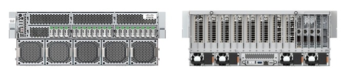
Cisco UCS C845A M8 Rack Server
The Cisco UCS C845A M8 is a flexible, 4-RU purpose-built AI platform that supports the full spectrum of AI use cases, from training and fine-tuning to distributed large model inferencing, including graphics acceleration in Virtual Desktop Infrastructure (VDI) deployments. The Cisco UCS C845A M8 is based on NVIDIA’s MGX architecture, specifically the PCIe Optimized 2-8-5-200 architecture when using 2 CPUs, 8 NVIDIA GPUs, 5 NVIDIA NICs, and 200Gbps of bandwidth per GPU to connect to backend (E-W) fabric.
Note: Cisco UCS C845A supports a maximum of 4 E-W NICs (1 NIC for every 2 GPUs) to connect the GPUs to the backend fabric and 1 N-S NIC to connect to the frontend fabric.
The Cisco UCS C845A M8 features two high-end AMD Turin (5th Gen) EPYC processors with up to 96 cores and 32 DDR5 RDIMM slots ( up to 4TB of memory). It is a versatile platform that can be scaled modularly to support 2, 4, 6 or 8 AMD or NVIDIA PCIe-based GPUs.
Dedicated, High-Speed GPU-to-GPU Interconnects
The high-speed interconnects within a Cisco UCS C845A are described below. They enable low-latency, high-bandwidth GPU-to-GPU connectivity to accelerate training and fine-tuning jobs:
● NVIDIA NVLink Bridges: On a system with NVIDIA GPUs, H200 NVL GPUs can be interconnected using 2-way NVLink (NVL2) or 4-way NVLink (NVL4) bridges. These bridges facilitate high-speed, direct GPU-to-GPU communication, ensuring efficient data and gradient synchronization. Note that NVIDIA L40S and RTX Pro 6000 GPUs do not support NVLink. RTPX Pro 6000 and L40S GPUs do not support NVLink.
● AMD Infinity Fabric Bridges: On a system with AMD MI210 GPUs, the GPUs are interconnected using 2-way or 4-way Infinity Fabric bridges, enabling direct GPU-to-GPU communication.
The direct GPU-to-GPU communication enabled by these dedicated interconnects bypasses the CPU and system memory for significantly faster data exchange and improved job completion times. It is important to adhere to recommended GPU population rules (see UCS 845A spec sheet in References section) to optimize NVLink/Infinity Fabric topology and prevent communication between GPUs on different PCIe switches from being routed through CPUs, which would introduce latency.
GPU Options
Each Cisco UCS C845A M8 server supports a flexible configuration of 2 to 8 PCIe GPUs (in even numbers, minimum 2), allowing you to choose the number of GPUs that match their specific use case and scale as workloads increase. GPUs cannot be mixed within a single server and must be procured from Cisco (requiring a unique SBIOS ID for CIMC). Table 3 lists the available GPU options on a UCS C845A M8 server, including capabilities such as NVLink and Multi-Instance GPU (MIG), and NVIDIA AI Enterprise (NVAIE) licensing requirements.
Table 3. Available PCIe GPU Options on Cisco UCS C845A M8 Server
| GPU Model |
Supported GPU Count |
Card/Slot Specs |
Memory, Power |
NVLink (NVL) / MIG Support |
NVAIE License |
| NVIDIA H100 NVL |
2, 4, 6, 8 |
FHFL, Single-Wide, 2-slot |
94GB, 400W |
NVL: Yes, 2-way MIG: Yes |
Included (5-Year License) |
| NVIDIA H200 NVL |
2, 4, 6, 8 |
FHFL, Single-Wide, 2-slot |
141GB, 600W |
Yes, 2/4-way MIG: Yes |
Included (5-Year License) |
| NVIDIA L40S |
2, 4, 6, 8 |
FHFL, Single-Wide, 2-slot |
48GB, 350W |
NVL: No MIG: No |
NOT Included |
| NVIDIA RTXP6000 |
2, 4, 6, 8 |
FHFL, Single-Wide, 2-slot |
96GB, 600W |
NVL: No MIG: Yes |
NOT Included |
| AMD MI210 |
2, 4, 6, 8 |
FHFL, Single-Wide, 2-slot |
64GB, 300W |
N/A |
N/A |
For up-to-date information on the GPU models available on the C845A, please see UCS C845A data and spec sheet links provided in the References section of this document.
External Network Connectivity for Scaling Training and Fine-Tuning Clusters
AI training and fine-tuning will typically require multi-node clusters, anywhere from 4, 8, 16 nodes to as high as 64, 128 nodes in enterprise deployments. To facilitate this scaling, Cisco UCS C845A M8 servers provide the following network interface options:
● NICs for connectivity to Backend (BE) / East-West (E-W) Fabric: Up to four PCIe Gen5 x16 FHHL slots are available for connectivity to East-West fabric (for example, NVIDIA ConnectX-7 (1x400G) or BlueField-3 B3140H SuperNIC (1x400G)). These are used for high-bandwidth, low-latency GPU Direct RDMA communication between GPUs residing on different C845A M8 servers connected to the same BE fabric.
● NICs for connectivity to Frontend (FE) / North-South (N-S) Fabric: One PCIe Gen5 x16 FHHL slot is available for connectivity to North-South fabric (for example, NVIDIA ConnectX-7 (2x200G) or BlueField-3 B3220 (2x 200G)). The FE fabric can be a dedicated fabric or an existing data center fabric and provides connectivity for AI workload management and orchestration components, access to high-speed storage, network services. When used for inferencing, inferencing requests from users and applications to models hosted on the Cisco UCS C845A will also use this NIC. The Cisco UCS C845A M8 server uses PCIe Gen5 for high-speed connectivity between GPUs and NICs, ensuring maximum data throughput.
Storage for Data-Intensive Workloads
AI training and fine-tuning are inherently data-intensive processes, requiring access to large datasets. The Cisco UCS C845A M8 platform supports the following storage options to meet these demands:
● Local High-Speed NVMe and SATA: Each Cisco UCS C845A M8 server can be configured with up to 20 E1.S NVMe SSDs for high-speed cache and data storage. These E1.S drives are available in capacities such as 1.9TB, 3.8TB, and 7.6TB. This capacity is beneficial for caching frequently accessed training data, storing intermediate results, or for checkpointing model parameters during long training runs, thereby reducing I/O latency and improving GPU utilization. Additionally, up to two M.2 SATA SSDs (240GB or 960GB) are available for booting the operating system, with an optional hardware RAID controller.
● External Storage Integration: For access to vast, shared datasets, the platform supports standard IP-based storage protocols such as NFS and object storage. In AI POD deployments, a dedicated storage NIC can be deployed to ensure consistent, high-bandwidth data transfer rates between the compute nodes and the external storage systems, preventing storage I/O from becoming a bottleneck to training performance. GPUDirect RDMA is also supported on the frontend NICs for high-speed, low latency connectivity between GPUs and external storage systems.
Building Block for Scale Units
The Cisco UCS C845A M8 server is also a foundational compute option for AI POD's modular Scale Units that will be discussed in a later section. Its modular design allows for flexible scaling of GPU count within a server and enables the creation of clusters tailored to specific AI needs. Multiple C845A servers can be combined with specific models of Cisco Nexus leaf switches to form distinct Scale Unit Types that enables customers to start with a cluster that meets their current needs, but that can scale to larger GPU clusters as their needs evolve, in a predictable and consistent manner.
Operating System Support
Cisco UCS C845A M8 server supports several Linux OS and Kubernetes. Supported OS include Ubuntu Server 22.04 LTS, 24.04 LTS, RedHat Enterprise Linux >9.4, RedHat Enterprise Linux CoreOS 4.16, and Rocky Linux 9.5. See Cisco UCS C845A M8 server spec sheet for an up-to-date list of supported OS types and versions.
Cisco Intersight
Cisco UCS servers can be managed through Cisco Intersight, providing unified, cloud-managed lifecycle management, policy-driven configuration, and comprehensive health monitoring. Intersight management of C845A includes capabilities such as server claiming, inventory display (CPU, GPU, Memory, NVMe Drives, and Network Cards), health and alerts management, KVM cross-launch, and power management. Additional capabilities will be included in the future, including real-time inventory updates, OS installation using KVM, tunneled KVM, connected TAC support, firmware management (including GPUs), advanced hardware monitoring, HCL, advisories, automated OS installation, and policy-driven management.
For more information, see Appendix A - References.
Network Fabric: Cisco Nexus 9000 Series Switches and Nexus Dashboard
In distributed training and fine-tuning, the network fabric plays a crucial role in providing high-bandwidth, low-latency communication to interconnect dense GPU servers like the UCS C885A and C845A. The Cisco Nexus 9000 series is designed to meet these demanding requirements, serving as the high-performance foundation for both the leaf and spine layers of the backend and frontend fabrics in the architecture.
The AI POD architecture leverages the following key platforms:
● Cisco Nexus 9332D-GX2B: A 1RU, 32-port 400GbE switch based on Cisco Cloud Scale technology, ideally suited for leaf role.
● Cisco Nexus 9364D-GX2A: A 2RU, 64-port 400GbE switch based on Cisco Cloud Scale technology, ideally suited for larger leaf or spine roles.
● Cisco Nexus 9364E-SG2 is a 2RU, 64-port 800GbE (or 128 x 400GbE ports) switch based on Cisco Silicon One technology. Designed for next-generation fabrics, it is available in QSFP-DD and OSFP form factors with dual-port transceivers for 400GbE connectivity, making it suitable for both leaf and spine roles.
All of these Nexus switches provide the port density, switching capacity, and advanced features necessary for AI/ML workloads, including support for RDMA over Converged Ethernet (RoCE), hardware-accelerated telemetry, and advanced load-balancing mechanisms.
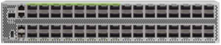
Cisco Nexus 9332D-GX2B Switch
The Cisco Nexus 9332D-GX2B is a 1RU switch engineered for high-density 400GbE leaf (or spine) deployments. With 32 flexible QSFP-DD ports, it provides the critical connectivity for dense GPU servers like the Cisco UCS C885A and Cisco UCS C845A. The switch delivers 25.6 Tbps of forwarding throughput and features a 60 MB shared buffer to manage traffic bursts and prevent packet loss in latency-sensitive AI environments.
![]()
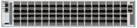
Cisco Nexus 9364D-GX2A Switch
For larger-scale deployments, the Cisco Nexus 9364D-GX2A is a 2RU switch that doubles the port density to 64 x 400GbE QSFP-DD ports, making it suitable for either a high-density leaf or a compact spine role. It provides 51.2 Tbps of throughput and a deep 120 MB shared buffer to maintain lossless performance across more expansive AI PODs.
Cisco Nexus 9364E-SG2 Switch
Based on Cisco Silicon One technology, the Cisco Nexus 9364E-SG2 is a 2RU switch designed for next-generation leaf and spine architectures. It features 64 native 800GbE ports, which can be configured to 128 ports of 400GbE using dual-port transceivers for maximum density. With 51.2 Tbps of throughput and a 256 MB on-die packet buffer, it is particularly well-suited for AI/ML, offering advanced congestion-management mechanisms and enhanced telemetry.
Common Capabilities for AI/ML Fabrics
All of these Nexus platforms provide the foundational features essential for building a high-performance AI network fabric:
● Lossless Transport for RDMA: They fully support RDMA over Converged Ethernet (RoCEv2), providing the low latency, high-bandwidth, and congestion-management necessary for distributed training.
● Advanced Fabric Features: They support modern network architectures using VXLAN EVPN and segment routing, allowing for the creation of flexible, scalable, and automated multi-tenant network infrastructures.
● Intelligent Traffic Management: These switches are particularly well-suited for AI/ML applications, supporting intelligent traffic management with features like Dynamic Load Balancing (DLB and advanced telemetry.
● Centralized Management: The entire fabric, including all leaf and spine switches, is managed through Cisco Nexus Dashboard, which provides a single point of control for automation, monitoring, and analytics.
Cisco Nexus Dashboard
The AI POD design for training and fine-tuning incorporates two distinct network fabrics: a backend (East-West) fabric for high-speed GPU-to-GPU connectivity between UCS GPU servers and a frontend (North-South) fabric for connectivity to management, storage, services, and user/application traffic. Cisco Nexus Dashboard (ND) provides a unified platform to simplify the deployment, management, and operations of these critical fabrics in the Cisco AI POD design.
The key capabilities that Nexus Dashboard provides for an AI POD include:
● Centralized Fabric Management
The latest release of ND 4.1 also consolidates Nexus Dashboard Fabric Controller, Orchestrator, and Insights into a single unified and cohesive platform with a single menu and API endpoint. This integration simplifies lifecycle management of multiple data center fabrics (both AI and non-AI) through one interface.
In the AI POD design, the same Nexus Dashboard is used to manage both AI fabrics (backend, frontend), providing operational consistency and simplifying the overall management of this environment.
● AI/ML Fabric Deployment and Blueprints
Nexus Dashboard provides built-in blueprints for flexible deployment of VXLAN EVPN-based or IP BGP fabrics, including templates, customized for enterprise AI deployments. These are pre-defined, best-practice templates to automate and accelerate the deployment of AI fabrics.
In the AI POD design, AI/ML templates are used to deploy both fabrics in a matter of minutes.
● Deep Visibility and Day-2 Operations
Nexus Dashboard offers comprehensive monitoring capabilities, including hardware-assisted telemetry, and real-time per flow analytics. ND also offers several day-2 operational capabilities such as centralized fabric upgrades and proactive fabric management by providing aggregated views of anomalies and advisories impacting the fabric, including an analysis hub with multiple troubleshooting tools.
● Scalable, Multi-Fabric Management
The Nexus Dashboard platform itself is designed for scale and resilience, allowing it to manage environments of any size. ND can be deployed as a physical or virtual appliance cluster (1, 3, or 6 nodes), including on the latest Cisco UCS M8-based appliances or in public clouds like AWS. For massive-scale deployments, several Nexus Dashboard clusters can be federated, providing a global view and management across multiple data centers and sites from a single pane of glass.
In the AI POD design, a single ND cluster, consisting of 3 physical nodes are used to manage both the backend and frontend fabrics.
● Automation and API Capabilities
ND offers robust automation with Infrastructure-as-Code (IaC) capabilities, enabling accelerated deployments and simplified workflows. A unified API endpoint across for multiple fabrics facilitates single API automation for fabric deployment, configuration, and ongoing management.
For more information, see Appendix A - References.
Storage
AI training and fine-tuning workloads are inherently data-intensive, requiring performant, scalable and reliable storage. For Cisco AI PODs, additional storage considerations include:
● Incremental scalability to meet evolving enterprise AI needs
● Flexibility to leverage established enterprise storage systems and newer solutions purpose-built for AI workloads
● Operational consistency across AI and non-AI environments
To meet these requirements, the Cisco AI POD solution integrates and validates proven enterprise storage solutions and Software-Defined Storage (SDS) solutions from industry-leading partners. The design ensures that these solutions provide the following core capabilities:
● High-Speed Connectivity: Storage systems typically connect to the frontend fabric in an AI network and require high-speed data connectivity with the compute nodes running AI workloads. In the AI POD design, this connectivity can be done using either dedicated or shared NICs. These NICs are typically 2 x 200GbE NICs, operating at 100Gbps or 200Gbps to ensuring high-bandwidth access to storage. NVIDIA recommends 12.5Gbps or more per GPU for storage access.
● GPU Direct Storage (GDS) Support: The AI POD design leverages GDS, which enables direct data transfer between storage and GPU memory, bypassing the system CPU and memory. This can significantly reduce latency and improve throughput for data-intensive AI operations, particularly for large datasets and workloads.
● Scalability and Flexibility: Integrated storage solutions should offer flexible scalability in both capacity and performance, allowing enterprises to grow their data stores as AI projects grow without disruption.
● Optimized Data Access: The solutions should support optimized data access like NFS over RDMA-that provide large GPU clusters with efficient parallel access to storage.
To deliver the above capabilities, Cisco has partnered with three key enterprise storage partners. The storage solutions validated in the AI POD solution are:
● NetApp Storage – NetApp offers a unified data platform with robust data management capabilities, making it a reliable choice for enterprises leveraging existing investments. NetApp's All-Flash FAS (AFF) systems, powered by ONTAP software, provide high-performance, all-flash NVMe-based storage. They support NFS, NFS over RDMA, object store and are validated for GDS, ensuring low-latency, high-throughput data access directly to GPUs.
ONTAP provides enterprise-class data management features like deduplication, compression, drive encryption, snapshots, replication, and backup, crucial for protecting valuable AI datasets and models. This extends existing data management practices to AI workloads, ensuring operational consistency. NetApp FlexGroup volumes are designed to handle massive, high-performance datasets, making them ideal for AI training workloads. Unlike traditional volumes, FlexGroup automatically distributes files and metadata across multiple constituent volumes and storage nodes, enabling parallel I/O operations. NetApp's scale-out architecture allows for seamless growth in both capacity and performance, adapting to evolving AI project needs.
NetApp’s latest AFX storage system is based on a next‑generation storage architecture that evolves the ONTAP storage model into a disaggregated high-performance NAS solution. AFX system delivers all the performance benefits of parallel file systems and niche AI storage solutions, but on an enterprise-grade platform that is simple, secure, and fully integrated. Unlike solutions that require proprietary file system clients, AFX uses standard file and object protocols, including parallel NFS (pNFS) for extreme performance and AWS S3-compatible object storage for flexibility. This integrated platform means that all of your applications can use AFX without installing custom clients that introduce instability, security risks, or operational complexity.
● Pure Storage - Pure Storage offers high-performance, all-flash solutions optimized for AI/ML in the FlashBlade//S systems. A scalable, all-flash, scale-out file and object storage platform designed for high-throughput, low-latency access to unstructured data. Its modular architecture allows for incremental scaling of both performance and capacity, making it ideal for large AI datasets and parallel access. FlashBlade//S supports high-speed 400GbE network interfaces and GDS integration.
◦ Portworx by Pure Storage - Portworx unlocks the value of Kubernetes data at enterprise scale. It’s a fully integrated container data platform that Automates, Protects, and Unifies modern applications across hybrid and multi-cloud, works with any underlying storage (on-prem or cloud) and any Kubernetes distribution, and simplifies developer actions and platform data management:
- Automate: Portworx automates Kubernetes data management end-to-end, boosting efficiency and time-to-market across DevOps/MLOps. It abstracts heterogeneous on-prem/cloud storage and delivers a cloud operating model with self-service storage/database services.
- Protect: Architect app-aware resiliency from Day 1 with synchronous DR (zero-data-loss targets) and automated Day-2 operations. Encrypt at cluster or storage-class scope, enforce RBAC, and use policy-driven backups with immutability/portability to counter ransomware.
- Unify: Unify Kubernetes storage by removing per-array CSI dependencies so platforms stay fully declarative across hybrid/multi-cloud. Manage data for containers and VMs in one solution—reducing VM licensing overhead and preserving future flexibility.
● VAST Storage - VAST Data's Universal Storage platform is an SDS platform designed for exabyte-scale and all-flash performance geared for AI workloads. Its Disaggregated Shared-Everything (DASE) architecture separates compute from storage, allowing independent scaling of resources to meet dynamic AI workload demands. This architecture provides high throughput and low latency for large datasets.
VAST Data Servers (EBox) can be deployed on Cisco UCS C225 M8 servers, leveraging Cisco's compute platform. When deployed on UCS C225s, the VAST Data Servers can be managed through Cisco Intersight, providing unified visibility and operational consistency for the compute layer of the storage solution within the broader AI POD infrastructure. VAST supports high-speed RDMA access and GDS.
AI Software Stack
A comprehensive and integrated software stack is essential for efficiently deploying, managing, and executing AI/ML workloads on the underlying infrastructure. Cisco AI PODs support a robust software ecosystem designed for high-performance computing and AI-specific tasks:
● Operating System: Cisco AI PODs support standard Linux distributions such as Ubuntu and Red Hat Enterprise Linux as the base OS on Cisco’s GPU-dense AI platforms (For a complete list of support distributions, see Cisco UCS Hardware Compatibility List (HCL) tool). For training and fine-tuning workloads, enterprises can choose to run AI workloads natively on these Linux distributions or combine it with a workload orchestration and management layer such as K8s.
● Workload Orchestration and Management: AI PODs integrate with workload managers (for example, SLURM, or Kubernetes’ native scheduling) to provide effective scheduling and orchestration of complex training jobs. Enterprise-grade Kubernetes platforms (for example, Red Hat OpenShift), serving as the de facto orchestration layer for AI/ML applications and services, can provide operational consistency across diverse AI workload environments, from inferencing to training and fine-tuning.
● NVIDIA Collective Communication Library (NCCL): Crucial for distributed training and fine-tuning, NCCL optimizes inter-GPU communication, ensuring efficient data exchange and synchronization across the GPU cluster for collective operations.
● NVIDIA AI Enterprise (NVAIE): This suite provides the core AI software libraries, frameworks (for example, PyTorch, TensorFlow), and tools necessary for developing and running high-performance AI applications. NVAIE ensures optimized performance and compatibility with NVIDIA GPUs. AI/ML frameworks can seamlessly leverage NCCL for optimal inter-GPU connectivity in distributed training and fine-tuning.
MLOps
In Red Hat OpenShift deployments, Red Hat OpenShift AI can serve as a robust, Kubernetes-native MLOps platform purpose-built for enterprise AI/ML workloads, addressing the evolving demands of regulated industries like finance, healthcare, and public sector. By building on OpenShift's hardened infrastructure, it unifies the AI lifecycle—from secure data ingestion and collaborative development in isolated projects to automated KFP pipelines, modular model customization with Training Hub and Kubeflow Trainer, distributed Ray-based training with GPU auto-scaling, and production-grade model serving via KServe with vLLM optimizations, llm-d distribution, and RAG capabilities. New AI safety features, such as guardrails and detectors for LLM filtering, enhance governance, ensuring ethical deployment and compliance with frameworks like NIST or CIS.
Enterprises gain substantial advantages:
● Scalability and Efficiency: Resource management with Kueue queuing, hardware profiles, and telemetry minimizes waste, enabling cost-effective handling of large datasets and models in hybrid environments.
● Security and Compliance: Inherited defense-in-depth (RBAC, SCCs, auditing) plus AI-specific guardrails reduce risks, avoiding custom implementations prone to gaps.
● Multi-Tenancy and Collaboration: Project isolation and RBAC support team workflows without overlays, fostering innovation while enforcing least privilege.
● Operational Reliability: Monitoring, versioned artifacts, and auto-scaling ensure reproducibility and uptime, with support for disconnected operations.
Management
The AI POD architecture takes a unified approach to management to ensure operational consistency and simplified scaling. The solution leverages two platforms for managing and operating the key infrastructure subsystems:
● Network Fabric Management: Cisco Nexus Dashboard offers unified control and visibility for the dual networks (backend and frontend fabric) in an AI training deployment. It streamlines network provisioning, operations, and troubleshooting, ensuring consistent network performance and health. As a centralized point of control, it also provides a single API endpoint for automating the end-to-end network infrastructure. Furthermore, Nexus Dashboard can manage multiple AI POD training or inferencing fabrics and can be federated with other clusters, providing a consistent management plane across both AI and non-AI data center environments.
● Compute Infrastructure Management: Cisco Intersight provides centralized, cloud-managed lifecycle management for all Cisco UCS compute resources, including the GPU nodes and management cluster servers. This SaaS-based platform (with an on-premises appliance option) enables policy-driven configuration, health monitoring, firmware management, and automation, simplifying compute operations. Support for the Cisco UCS C8xx series within Intersight is continually evolving, and it is recommended to consult the latest documentation for current capabilities.
The two platforms together, Cisco Nexus Dashboard for the network and Cisco Intersight for the compute, provide a complete, end-to-end management framework for the AI POD architecture.
Observability
Unified, end-to-end visibility are critical for operationalizing AI at scale within the enterprise in order to simplify complex infrastructure and to identify and resolve issues faster when they occur.
Cisco Splunk Observability Cloud delivers comprehensive, full-stack observability across the entire AI/ML environment, from infrastructure (compute, network, storage) to applications and workloads. This integrated visibility helps eliminate management silos, enables proactive monitoring, facilitates rapid root cause analysis, and supports performance optimization.
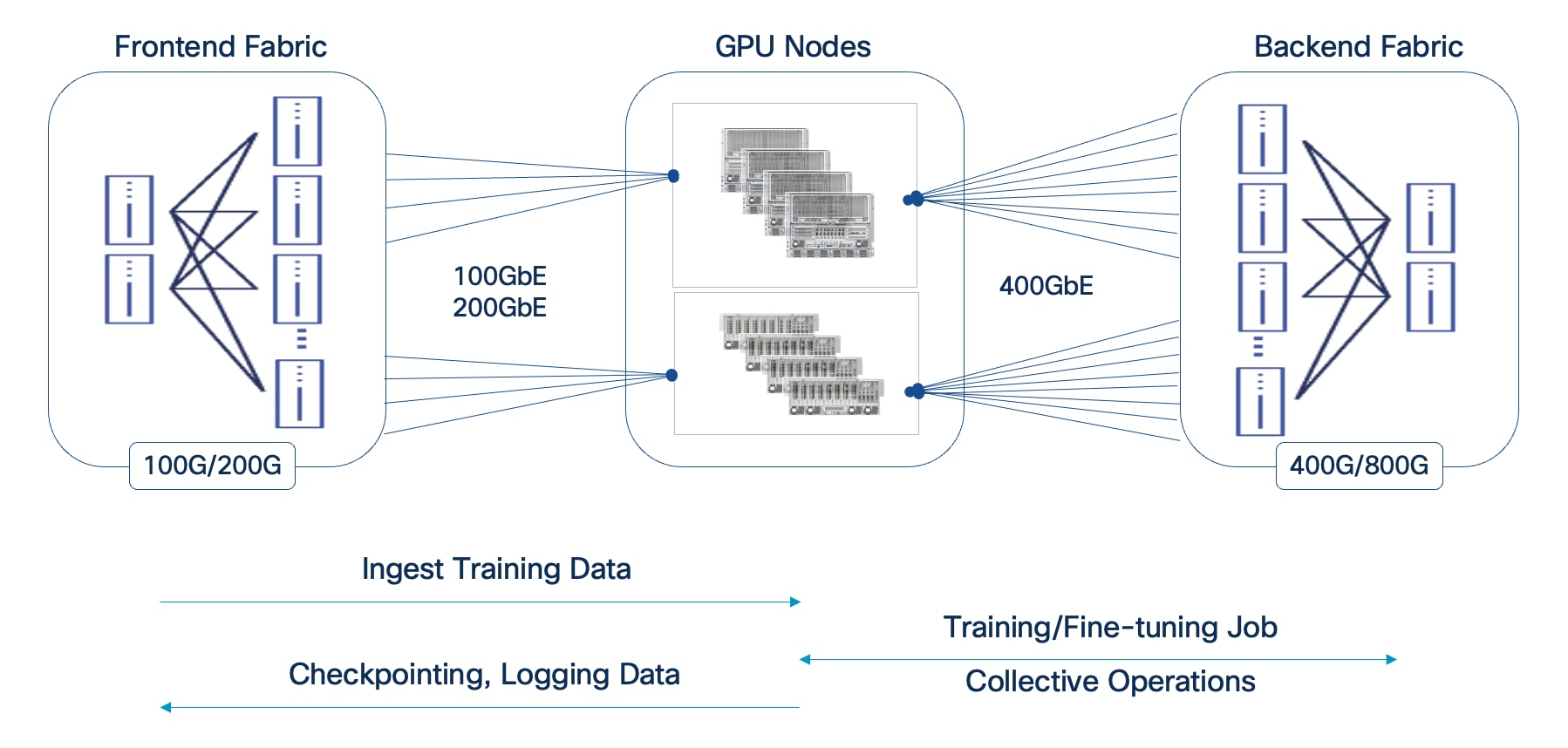
Dual Fabrics: Backend and Frontend Networks
Cisco AI POD architecture is a dual-fabric design to meet the stringent performance requirements of distributed training and fine-tuning AI workloads. Distributed training and fine-tuning have fundamentally different communication patterns and performance requirements from those for management, storage access, or user/application traffic.
● Backend (East-West) Fabric: This fabric is a dedicated, isolated, high-performance backend fabric for low latency, high-throughput, and lossless GPU-to-GPU communication using GPU Direct RDMA (RoCEv2). This isolation ensures that collective operations and data synchronization between GPUs during training and fine-tuning are not impacted by other network traffic, directly contributing to faster Job Completion Times (JCTs).
● Frontend (North-South) Fabric: This fabric handles management traffic, high-speed storage access including GPU Direct Storage, and seamless integration with the broader enterprise data center network. It provides robust connectivity for accessing enterprise data, data center services as well as user/application traffic. The separation of BE and FE fabrics ensures consistent and reliable connectivity for all supporting services without compromising the performance of the core AI workload.
Modular and Scalable Design: Scale Units and Scale Unit Types
The AI POD architecture is designed to be modular with consistent scalability and operations that allow enterprises to grow their AI infrastructure in a predictable manner as needs evolve. This is achieved through the concept of Scale Units and Scale Unit Types. Enterprises can select from one of the pre-defined Scale Unit Types as their starting cluster and then expand to larger cluster sizes as their needs grow. If a customer knows their end scale target, this can be factored into the selection early.
● Scale Units as Building Blocks: A Scale Unit is a foundational, repeatable building block that combines Cisco UCS compute nodes (equipped with high-performance GPUs) and Cisco Nexus leaf switches. Each Scale Unit is engineered to deliver a specific cluster size of AI compute and network capacity. Multiple Scale Unit Types are defined based on the Nexus leaf switch model used with a direct bearing on the GPU cluster size. Both Cisco Nexus Cloudscale and Silicon One (S1) switches are supported.
● Predictable Scale-Out: Larger AI POD clusters can be built out by incrementally adding and interconnecting these individual Scale Units in a robust spine-leaf network topology. This approach ensures that performance scales predictably and consistently, avoiding bottlenecks as the AI deployment expands.
● Flexibility and Right-Sizing: Scale Units come in various configurations (for example, supporting 32, 64, or 128 GPU clusters), allowing enterprises to right-size their initial AI POD deployment to match current workload demands. This modularity provides the flexibility to expand capacity precisely when needed, preventing costly over-provisioning and ensuring efficient resource utilization over time.
● Operational Consistency at Scale: Enterprises can adopt additional scale units as their needs evolve without changing their operational model. The new scale units can be added to an existing backend fabric and managed through Nexus Dashboard. The frontend fabric that supports the backend fabric is also managed through Nexus Dashboard, providing management consistency across fabrics as well.
Design
This chapter contains the following:
● Backend Fabric Design (East-West)
● Frontend Fabric Design (North-South)
● MLOps using Red Hat OpenShift AI
This chapter moves from the high-level architecture to the detailed subsystem design, providing the specific designs for the backend and frontend fabrics, compute, storage, and management layers that form the complete AI POD solution for distributed training and fine-tuning.
AI training and fine-tuning workloads, and the associated GPU clusters, typically rely on two independent networks: a backend (BE) for parallel processing and synchronization across GPU nodes, and a frontend (FE) network for ingesting training data, checkpointing, and logging (Figure 8). In hybrid deployments, the frontend network also handles inferencing traffic from users, applications, and other services. In enterprise deployments, the frontend network can be an existing data center network that meets the requirements. Unlike frontend fabrics, backend fabrics are isolated, typically with no outside network access to other parts of the enterprise or external networks.
Note: A backend fabric is typically not used or necessary in an inferencing only deployment.
In enterprise deployments, the frontend fabric could be an existing enterprise data center fabric that meets the requirements. In this scenario, the storage could be connected to the same fabric, or a dedicated AI storage fabric could also be deployed.
Backend Fabric Design (East-West)
This section details the design of the Backend (East-West) Fabric. In distributed AI model training and fine-tuning, this fabric is critical for performant GPU-GPU communication and data exchange during collective operations, directly impacting the JCT of training workloads. The GPU nodes (like Cisco UCS C885A and Cisco UCS C845A) are typically dense GPU platforms that connect to this fabric using dedicated Network Interface Cards (NICs), separate from those used for the FE fabric.
As discussed, enterprises typically do not train large foundational models (like LLMs) from scratch for their AI initiatives and use cases. Instead, they focus on customizing these pre-trained models with their organization’s data, often using fine-tuning, Retrieval-Augmented Generation (RAG), or a combination of both approaches. These customization workloads, while resource-intensive, require significantly fewer GPUs (magnitudes less) and supporting infrastructure compared to the initial training of these models. The Cisco AI POD's Backend Fabric is purpose-built and designed to meet these distinct characteristics and stringent requirements of enterprise AI workloads, as previously described.
Key Requirements
The performance of AI training and fine-tuning workloads, and therefore the backend fabric, is based on JCT. Therefore, the fabric must be designed to meet critical network requirements that ensure optimal JCTs.
Note: As previously discussed, the acceptable JCT is subjective to each organization and may depend on the specific AI initiative or use case, as well as the characteristics of the workload itself (for example, model size, dataset size).
To ensure optimal JCT, the backend fabric must provide the following:
● High Bandwidth: To handle concurrent, large data (elephant) flows between GPUs.
● Low End-to-End Latency: To minimize data exchange delays between nodes, as these directly impact JCT.
● Lossless Fabric: To avoid network interruptions or lost packets that can force training jobs to restart, significantly affecting JCT
● Low Jitter: As fast, bursty GPU operations can cause buffer overflows, leading to temporary congestion if not managed.
● Efficient Load Balancing: AI training workloads typically have low entropy, which can make traditional load balancing methods like ECMP sub-optimal. ECMP is designed for high-entropy flows common in enterprise data centers but may be less than ideal for AI workloads due to the low variability exhibited by these flows.
Note: The low entropy is a significant concern when all GPUs are assigned to a single training job. However, as the number of concurrent training workloads on the fabric increases, the entropy also increases. Monitoring the backend fabric to understand these traffic patterns will allow you to understand the needs of your environment.
Modular Design Tailored for Enterprise AI
The backend fabric in AI POD uses a modular architecture built around the concept of Scale Units (SU). As outlined in NVIDIA's Enterprise Reference Architecture (ERA) for HGX-8-9-400 architectures (like Cisco UCS C885A), NVIDIA defines Scale Units as pre-defined units of four GPU compute nodes. These units provide a flexible and granular approach to scaling AI training infrastructure.
Scale Units
In the Cisco AI POD for training architecture, the Scale Unit definition has been expanded to include a pair of network switches and the GPU compute nodes that connect to them. The different Nexus data center switches used in the AI POD architecture are right-sized to support the GPU node scale for that SU, resulting in three distinct Scale Unit Types (see Table 4 and Table 5). These scale unit types serve as foundational building blocks in the Cisco AI POD architecture for building a backend fabric for training and fine-tuning. It is important to note that these pre-defined compute-plus-network units are designed to align with the typical GPU cluster sizes that enterprises need for fine-tuning and customization.
Unlike the thousands of GPUs required for training large LLMs from scratch, enterprise fine-tuning and customization workloads typically require smaller GPU clusters, though they often need to support multiple such workloads running concurrently. To address this, the Cisco AI PODs architecture provides multiple Scale Unit Types that enterprises can select from as a starting point. Organizations can then incrementally grow their cluster with consistent performance and design methodology. This modular approach enables enterprises to right-size their infra to meet their current workload needs, but then seamlessly expand by adding more scale units as AI projects evolve. See next section for detailed descriptions and scaling options.
Table 4. Scale Unit Types for AI PODs with Cisco UCS C885A M8 Servers
| Scale Unit Type |
Nexus Switch Model & Count |
UCS C885A Nodes (Max) |
GPU Cluster Size (Max per SU) |
| Scale Unit – Type 1 |
2 x N9k-C9332D-GX2B |
Up to 4 Nodes |
Up to 32 GPUs |
| Scale Unit – Type 2 |
2 x N9k-C9364D-GX2A |
Up to 8 Nodes |
Up to 64 GPUs |
| Scale Unit – Type 3 |
2 x N9k-C9364E-SG2 |
Up to 16 Nodes |
Up to 128 GPUs |
Table 5. Scale Unit Types for AI PODs with Cisco UCS C845A M8 Servers
| Scale Unit Type |
Nexus Switch Leaf Pair |
UCS C845A* Nodes |
GPU Cluster Size* |
| Scale Unit – Type 1 |
2 x N9k-C9332D-GX2B |
Up to 8 Nodes |
Up to 64 GPUs |
| Scale Unit – Type 2 |
2 x N9k-C9364D-GX2A |
Up to 16 Nodes |
Up to 128 GPUs |
| Scale Unit – Type 3 |
2 x N9k-C9364E-SG2 |
Up to 32 Nodes |
Up to 256 GPUs |
*On a Cisco UCS C845A M8 server, 2 GPUs share 1 East-West NIC for connecting to the BE fabric. This reduces the number of switch ports required per node, allowing for a higher node count and GPU density per Scale Unit Type when compared to using Cisco UCS C885A. This also assumes an 8-GPU configuration per C845A node.
Scale Unit Types: Configurations and Scaling Options
This section provides additional details on each of the scale unit types introduced in the previous section. These units serve as the foundational building blocks for the AI POD infrastructure, combining Cisco UCS compute nodes and Cisco Nexus leaf switches to deliver right-sized infrastructure of varying GPU cluster sizes for enterprise AI training and fine-tuning workloads.
Note: Though not shown, each scale unit type in the figures below connects to a pair of Spine switches (recommended). Also, each scale unit type is rail-optimized within the SU.
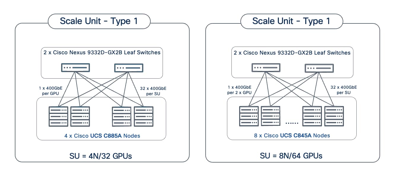
Scale Unit - Type 1
Scale Unit Type 1 consists of 2 Cisco Nexus 9332D-GX2B Cloudscale switches with up to:
● 4 x Cisco UCS C885A M8 servers (4 nodes, 32 GPUs), with each server connecting to leaf switches using 8 x 400GbE links.
● 8 x Cisco UCS C845 M8 servers (8 nodes, 64 GPUs), with each server connecting to leaf switches using 4 x 400GbE links.
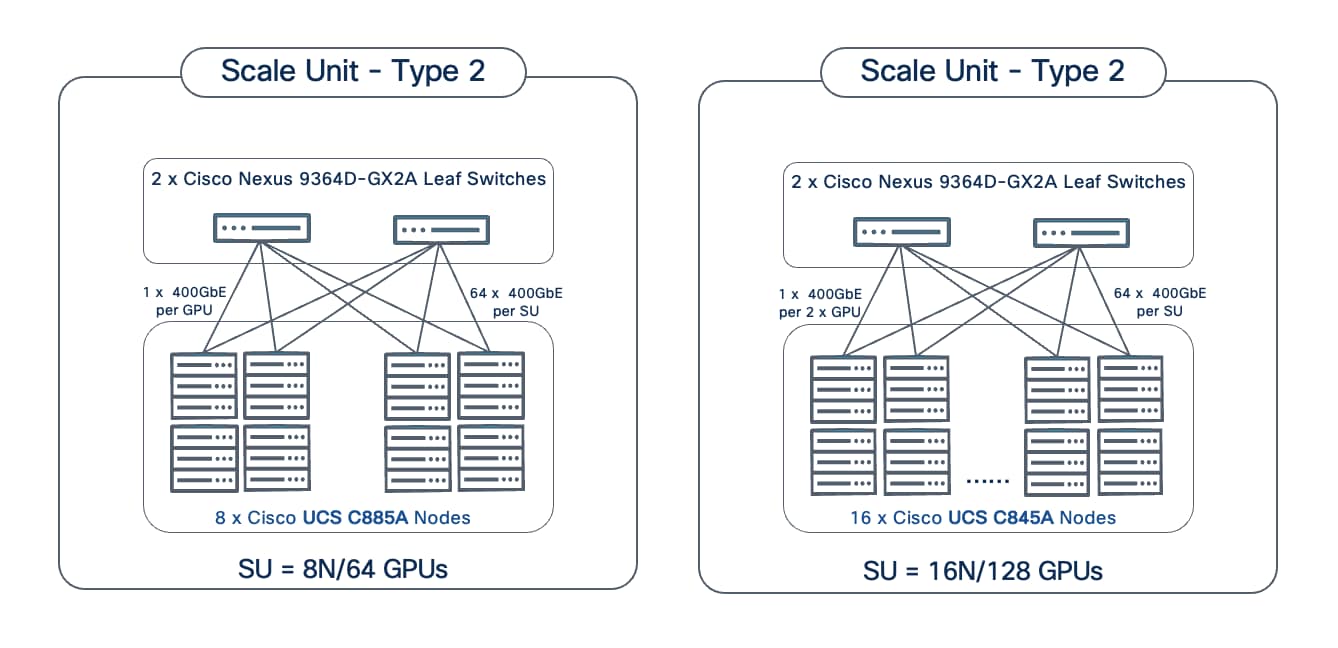
Scale Unit - Type 2
Scale Unit Type 2 consists of 2 Cisco Nexus 9364D-GX2A Cloudscale switches with up to:
● 8 x Cisco UCS C885A M8 servers (8 nodes, 64 GPUs), with each server connecting to leaf switches using 8 x 400GbE links.
● 16 x Cisco UCS C845 M8 servers (16 nodes, 128 GPUs), with each server connecting to leaf switches using 4 x 400GbE links.
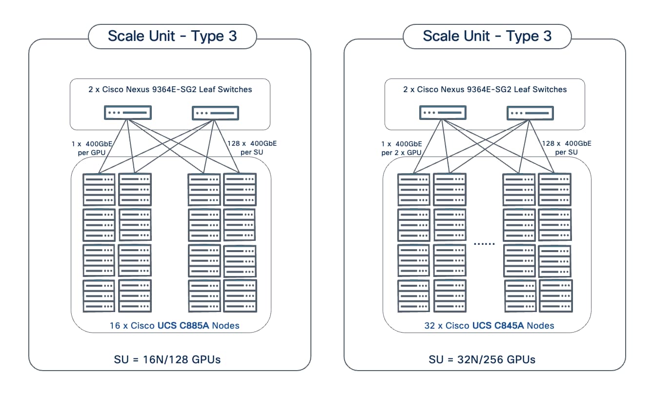
Scale Unit - Type 3
Scale Unit Type 3 consists of 2 Cisco Nexus 9364E-SG2 Silicon One switches with up to:
● 16 x Cisco UCS C885A M8 servers (16 nodes, 128 GPUs), with each server connecting to leaf switches using 8 x 400GbE links.
● 32 x Cisco UCS C845 M8 servers (32 nodes, 256 GPUs), with each server connecting to leaf switches using 4 x 400GbE links.
The individual Scale Unit Types described above represents the starting point for an AI POD infrastructure for training and fine-tuning. As AI infrastructure needs grow, enterprises can expand to larger GPU clusters by adding additional Scale Units. This may involve adding more scale units of a given type to the same Spine switch pair or may require adding additional spine switch pairs to support a greater number of Scale Units. For a comprehensive overview of how the different scale unit types can be scaled to achieve large cluster sizes, go to Scale the Backend Fabric.
Network Topology
The backend fabric provides the optimal networking for GPUs in a cluster to communicate with each other in a multi-node environment, which is critical for accelerating distributed AI/ML training and fine-tuning.
Spine-Leaf Clos Topology
The backend (East-West) fabric in the Cisco AI POD architecture is a two-tier, non-blocking spine-leaf (Clos) design, built using Cisco Nexus 9000 series switches. This fabric is ideal for the heavy "east-west" traffic common in AI/ML training and fine-tuning fabrics.
In the AI POD architecture, each scale unit, which includes a pair of leaf switches, is integrated into a larger spine-leaf design. While other valid designs such as single switch or two switches with cross-links are possible, the minimal configuration recommended in a Cisco AI POD architecture is a 2-spine, 2-leaf design for all Scale Unit Types as shown in Figure 12.
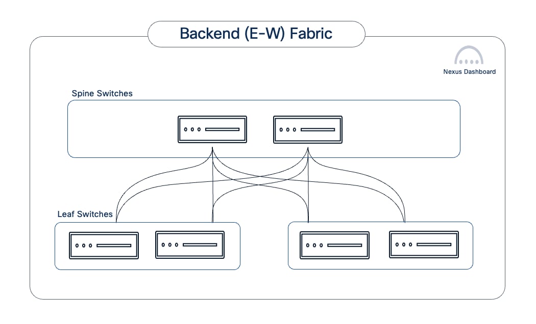
This spine-leaf architecture delivers several key benefits for AI workloads. It ensures low, predictable latency, with GPU node-to-node communication in a 2-tier design being either one (intra-leaf) or two (inter-leaf) network hops away, which is critical for AI training jobs. The high-bandwidth, non-blocking fabric with efficient load-balancing mechanisms, maximizes link utilization and minimizes bottlenecks. The design also scales with ease and consistency, allowing AI clusters to be easily expanded by adding leaf or spine switch pairs as needed. This extensibility, coupled with the inherent benefits that a spine-leaf topology provides, makes it the recommended AI POD design even for small starter deployments. The impact of adding a spine layer in these starter deployments is minimal when you consider the longer-term value of this design, especially when combined with the operational benefits of Cisco Nexus Dashboard.
The spine and leaf switch models for each Scale Unit Type in the AI POD architecture is shown in Table 6.
Table 6. Spine and Leaf Switch Models for each Scale Unit Type
| Scale Unit Type |
Nexus Leaf Switch Model & Count |
Nexus Spine Switch Model & Count |
| Scale Unit – Type 1 |
2 x N9k-C9332D-GX2B |
2 x N9k-C9364D-GX2A |
| Scale Unit – Type 2 |
2 x N9k-C9364D-GX2A |
2 x N9k-C9364D-GX2A |
| Scale Unit – Type 3 |
2 x N9364E-SG2 |
2 x N9364E-SG2 |
Using Scale Unit Type 1 as an example, the backend fabric in the AI POD would minimally be as shown in Figure 13.
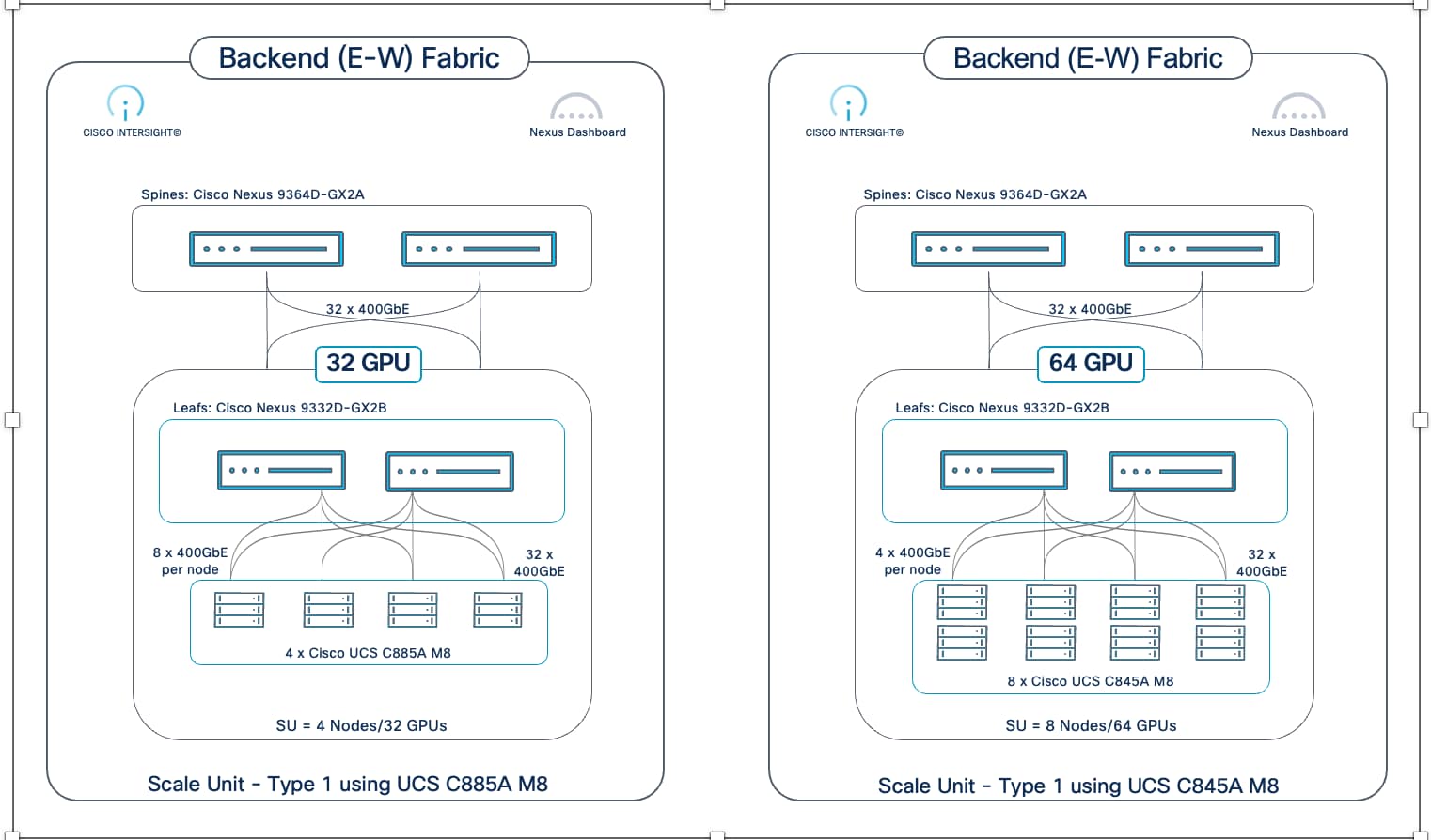
As previously discussed, the inherent scalability of a spine-leaf architecture, combined with the modularity of Scale Unit Types, enables an AI POD backend fabric to scale-out with predictable performance and capacity, avoiding over-provisioning. Enterprises can start with a pre-defined Scale Unit Type and then incrementally expand by adding more Scale Unit Types (with their leaf pairs) as use cases and needs grow (Figure 14). This allows for a repeatable, modular scale-out, ensuring a right-sized, predictable design and consistent performance as the fabric expands.
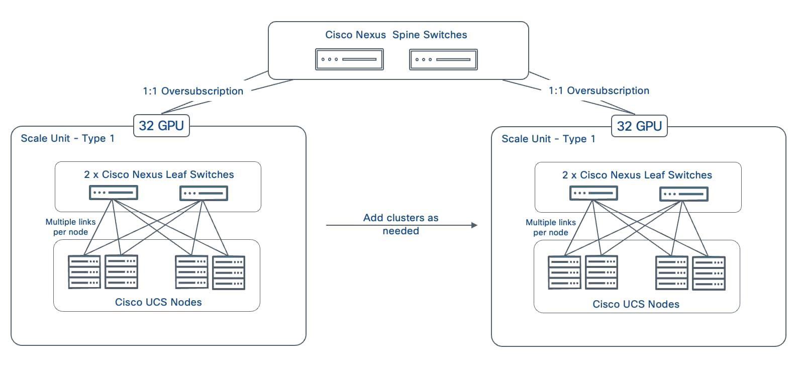
The base spine-leaf topology for Scale Unit – Type 1 as shown in Figure 13 can be scaled by adding more instances of this type to a single spine pair. The same approach can also be used to scale the other Scale Unit Types. Table 7 lists the maximum GPU scale possible for each Scale Unit Type as you add additional instances (leaf pairs with attached GPU nodes) to a single pair of spine switches.
Table 7. Scale-Out Maximum for Scale Unit Types using 2 x Spine Switches
| Scale Unit Type (SUT) |
Nexus Spine Switch Model |
Nexus Leaf Switch Model |
GPU / Node (N) Count for UCS C885A (Max Scale) |
GPU / Node (N) Count for UCS C845A (Max Scale) |
| SU-T1 |
N9k-C9364D-GX2A |
N9k-C9332D-GX2B |
128 GPUs / 16N using 4 Leaf pairs |
256 GPUs / 32N using 4 Leaf pairs |
| SU-T2 |
N9k-C9364D-GX2A |
N9k-C9364D-GX2A |
128 GPUs / 16N using 2 Leaf pairs |
256 GPUs / 32N using 2 Leaf pairs |
| SU-T3 |
N9364E-SG2 |
N9364E-SG2 |
256 GPUs / 32N using 2 Leaf pairs |
512 GPUs / 64N using 2 Leaf pairs |
Note: On a Cisco UCS C845A M8 server, 2 GPUs share 1 East-West NIC for connecting to the BE fabric. This results in higher GPU cluster sizes compared to a C885A for the same leaf-spine combination.
To scale beyond a spine pair, additional spine pairs can be added and effectively double the scaling capacity of existing cluster and while maintaining a non-blocking fabric.
Note: Adding spine pairs requires re-cabling to distribute leaf-to-spine links across all spines.
Table 8 lists the maximum GPU scale possible for each Scale Unit Type as you add additional spine pairs (with attached leaf pairs and GPU nodes).
Table 8. Scale-Out Maximum for Scale Unit Types using 4 x Spine Switches
| Scale Unit Type (SUT) |
Nexus Spine Switch Model |
Nexus Leaf Switch Model |
GPU / Node (N) Count for UCS C885A (Max Scale) |
GPU / Node (N) Count for UCS C845A (Max Scale) |
| SU-T1 |
N9k-C9364D-GX2A |
N9k-C9332D-GX2B |
256 GPUs / 32N using 8 Leaf pairs |
512 GPUs / 64N using 8 Leaf pairs |
| SU-T2 |
N9k-C9364D-GX2A |
N9k-C9364D-GX2A |
256 GPUs / 32N using 4 Leaf pairs |
512 GPUs / 64N using 4 Leaf pairs |
| SU-T3 |
N9364E-SG2 |
N9364E-SG2 |
512 GPUs / 64N using 4 Leaf pairs |
1024 GPUs / 128N using 4 Leaf pairs |
To scale to even higher cluster sizes, enterprises can take two approaches:
● Multiple isolated fabrics: Replicate the two-tier spine-leaf fabric at a given scale to create a completely new, independent fabric to double the GPU cluster size. This involves scaling an existing fabric to a pre-determined max. scale (see earlier discussion in this section) and then deploying a second fabric that can also be incrementally scaled to the same max. capacity. The second cluster could use a different Scale Unit Type and switch model (spine/leaf) to achieve a different max. scale as well. This scaling approach effectively creates islands of GPU clusters of a given scale. There is no connectivity between these fabrics so a workload can only be deployed in one fabric – it cannot span fabrics and use available GPU capacity in other fabrics). This approach is simpler and more balanced if the max scale of each cluster is sufficient for the largest training and fine-tuning workload that the enterprise has.
● Expand existing fabric to a third-tier (Super Spine): Add a third tier or super-spine layer to the existing spine-leaf fabric. (Note: If you plan to add a third tier, you may want to reserve downlink ports on existing spine switches for this expansion. This will impact the maximum scale of your 2-tier design and adds complexity and latency to the overall design) This approach allows workloads to use the full GPU capacity available across the fabric, though the latency will be higher when GPU-to-GPU communication requires traversing the additional tier.
For both scaling strategies, Cisco Nexus Dashboard simplifies the deployment and management of these scaled fabrics. A single Nexus Dashboard cluster can support multiple fabrics, as its scale is based on the total switch count across all fabrics, not the number of fabrics.
The architectural approach outlined in this section, built on repeatable and modular Scale Units within a spine-leaf topology, provides a foundational architecture that enables organizations to extend their infrastructure in a consistent and repeatable manner. As a result, resources can be scaled as needed, while maintaining architectural and operational consistency—eliminating the need for complex redesigns as cluster sizes grow and ensuring the infrastructure remains flexible and easy to manage as enterprise AI needs evolve.
Fabric Optimizations and Technologies
To meet the stringent demands of AI training and fine-tuning workloads, this section outlines the key technologies and optimizations leveraged in the AI POD backend fabric to deliver lossless, low latency, high-bandwidth, GPU-direct RDMA communication between GPUs in Cisco UCS nodes.
Non-Blocking Fabric
The fabric is designed to be non-blocking and uses 400GbE links end-to-end to provide full 400Gbps of bandwidth from GPU-to-GPU as illustrated in in Figure 15.
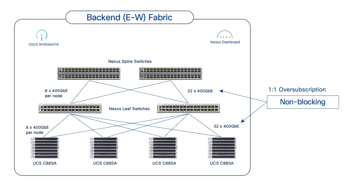
The non-blocking fabric is achieved by ensuring that the aggregate bandwidth from the UCS nodes to the leaf switches equals the aggregate bandwidth from the leaf switches to the spine switches as shown. The non-blocking design shown is a 4-node Cisco UCS C885A cluster with eight GPUs and eight NICs in each node with a total of 32 uplinks (4 Nodes x 8 GPUs = 32links) distributed across 2 leaf switches. This design provides 1:1 oversubscription by matching the total number of downlinks from both leaf switches to the number of uplinks to the spine switches. The traffic between any two UCS nodes will have the full 400GbE bandwidth across the fabric. The spine-to-leaf links can also use 800GbE (when using Scale Unit – Type 3 and N9364E-SG2-O with OSFP transceivers) in preparation for 800GbE end-to-end when 800GbE NICs are available.
Quality of Service (QoS)
For GPUDirect RDMA and RoCEv2 to deliver performant inter-node GPU-to-GPU communication across the backend fabric, the fabric must provide a lossless environment. Any packet loss in this communication can have a significant impact on job completion times. Therefore, the backend fabric should have QoS features in place to ensure lossless communication for AI/ML workloads.
Cisco Nexus switches, deployed in AI POD backend fabrics, provide comprehensive QoS features to ensure a lossless ethernet/IP fabric for RoCEv2, supporting both IP/BGP and VXLAN EVPN fabrics. Implementing QoS typically involves:
● Marking the traffic at the edge (by endpoints typically)
● Classifying and queueing the marked traffic across the fabric
● Using congestion avoidance mechanisms to prevent input and output buffer overruns
For lossless, end-to-end (GPU-to-GPU), RoCEv2 communication across the backend fabric, the following QoS mechanisms is recommended for the Nexus backend fabric.
Marking and Classification based on IP/DSCP
To identify and prioritize RoCEv2 traffic and other critical traffic through the backend fabric, appropriate QoS marking (primarily, by GPU nodes) should be on all traffic incoming into the fabric. In an AI/ML backend fabric, majority of the traffic is RoCEv2 data. However, critical congestion notification traffic such as Congestion Notification Packet (CNP) generated by switches experiencing congestion, also needs to be marked, classified and prioritized to prevent packet loss. The pre-marked traffic is then classified accordingly by all Nexus switches in the fabric.
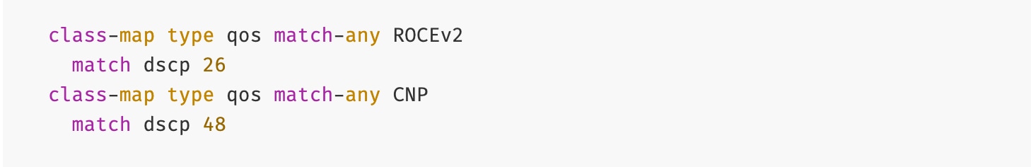
The classified RoCEv2 and CNP traffic is then mapped to an internal QoS group and then used to determine queueing policy. This policy is deployed on all leaf switches in the backend fabric is shown below:
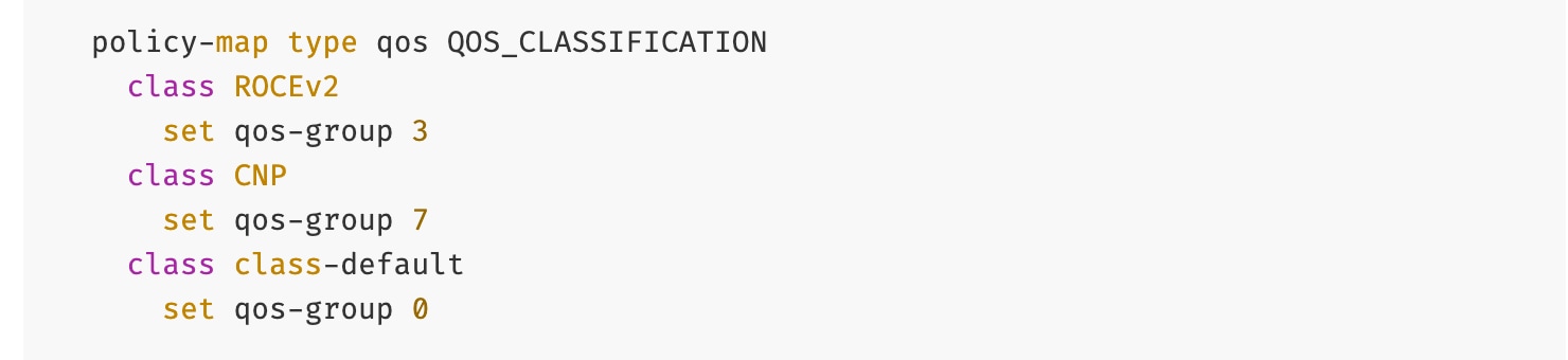
Queuing with Congestion Avoidance (WRED, ECN and CNP)
The classified traffic is used to apply outbound queueing policies – RoCEv2 using QoS group 3 is mapped to the specific queuing policy with a significant majority of bandwidth allocated to the queue while CNP using QoS Group 7 is mapped to a priority queue, ensuring it receives absolute priority over any other traffic in the event of congestion. Congestion avoidance mechanisms, specifically Weighted Random Early Detection (WRED) with ECN, are configured for RoCEv2 queuing policy. WRED uses buffer utilization thresholds to proactively indicate and prevent congestion that could lead to packet loss.
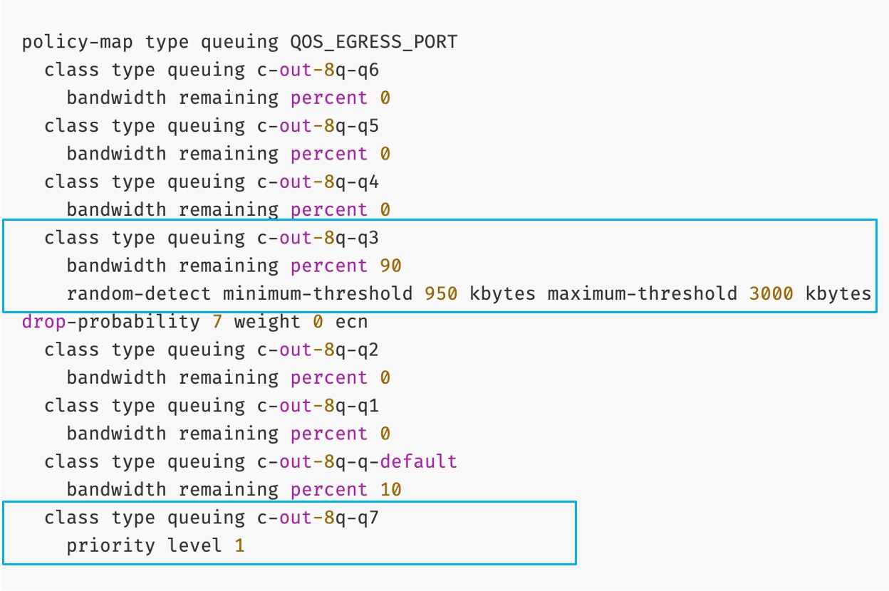
Based on this configuration, when the queue depth for RoCEv2 traffic exceeds the minimum-threshold (950 KB), packets are randomly marked to indicate Congestion Experienced using the ECN bits in the IP/TOS header. As the queue approaches the maximum-threshold (3000 KB), the probability of marking increases. If the maximum threshold is reached, all packets are marked. This marking signals to the receiving endpoint (or intermediate switches) that congestion is being experienced.
Priority Flow Control
PFC is a link-layer, hop-by-hop, flow control mechanism, based on IEEE 802.1Qbb. PFC can signal congestion and prevents packet loss by pausing traffic for specific classes. Unlike other link-layer flow control mechanisms, PFC’s can indicate congestion on a per traffic-class basis, using link-layer Class-of-Service (CoS) bits to specify which traffic needs to be throttled. When congestion occurs for a specific CoS, indicated by its buffer exceeding the configured threshold, PFC sends ‘pause’ frames towards the source, until the buffer utilization falls below the threshold. On Nexus switches, the PFC policy uses the default thresholds on Nexus switches. PFC policy is deployed on all (leaf) switches in the backend fabric.
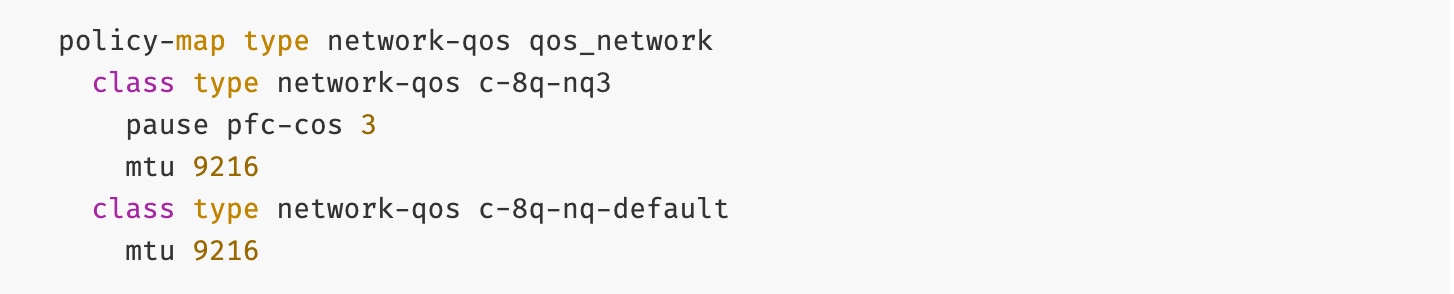
Explicit Congestion Notification
ECN provides end-to-end congestion signaling between IP endpoints to react proactively and reduce transmission rates before packet loss occurs. ECN uses 2 bits in the Type of Service (ToS) field of the IP header to indicate its congestion capabilities and state (Not ECN capable, ECN Capable, and Congestion Encountered). As discussed, when buffer utilization on the switches reach the first or minimum threshold set for WRED, they will start marking some packets with the ECN bit set instead of dropping them. When the second WRED threshold is reached, ECN will start marking all packets towards the destination and start sending CNP packets towards the source to throttle transmission.
Applying QoS Policies on Nexus Switches
The policies (output) shown below are either applied globally or at the interface level (input) on all Nexus switches:
Example Global policy:
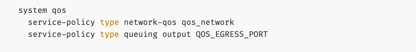
Example interface policy:
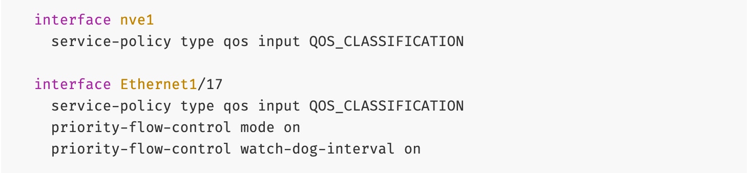
Note: Data Center Quantized Congestion Notification (DCQCN) on Nexus series switches is a combination of PFC and ECN QoS mechanisms that work in tandem to achieve a lossless ethernet/IP fabric.
Load Balancing (LB)
Load balancing in AI/ML backend fabrics is critical for optimizing the east-west traffic flows generated by distributed training workloads in typical spine-leaf topologies with multiple parallel paths between compute nodes. Traditional ECMP is often inefficient for AI workloads due to low traffic entropy and synchronized collective communication operations (All-Reduce, All-to-All, All-Gather) that create large elephant flows. Cisco Nexus 9000 Series switches provide advanced adaptive load balancing algorithms that dynamically monitor link utilization and flow characteristics, ensuring optimal bandwidth utilization while minimizing congestion and packet reordering that can significantly impact training performance.
Cisco Nexus switches support several load balancing mechanisms for AI/ML fabrics as listed below:
● Hash-Based ECMP Load Balancing: Distributes flows across equal-cost paths using hash algorithms based on packet headers (5-tuple: source/destination IP, source/destination port, and protocol). While simple and deterministic, this method can lead to uneven distribution with large, synchronized AI flows, resulting in persistent congestion on some links while others remain underutilized. This remains the most common approach in traditional data centers but is increasingly inadequate for modern AI workload demands.
● Flowlet-Based Load Balancing: Splits flow into smaller "flowlets" (bursts of packets separated by idle gaps) and dynamically redistributes them across available paths based on real-time link utilization. This provides better load distribution for elephant flows while maintaining packet ordering within flowlets, addressing some of the limitations of static hash-based methods. Flowlet switching operates at microsecond granularity, making it well-suited for the bursty nature of GPU collective operations.
● Dynamic Load Balancing (DLB): Continuously monitors path conditions and makes per-flowlet forwarding decisions based on actual link utilization, queue depths, and latency metrics. DLB provides superior performance for AI workloads by actively avoiding congested paths and dynamically adapting to changing traffic patterns.
● Adaptive Routing (NVIDIA Spectrum-X): NVIDIA's implementation combines switch-level and NIC-level intelligence, where the BlueField-3 SuperNIC collaborates with Spectrum-X switches (and now Nexus switches) to make routing decisions based on congestion. This creates a tightly integrated, closed-loop system specifically optimized for NVIDIA's ecosystem. This requires additional licenses on Cisco Nexus switches – for information about the Fine Grain Load balancing line item, go to the Bill of Materials.
● Ultra Ethernet Consortium (UEC) Load Balancing Mechanisms: An emerging industry standard for vendor-neutral adaptive routing in AI fabrics that Cisco is actively contributing to and implementing. UEC defines standardized mechanisms including in-band telemetry that embeds real-time congestion metrics into packet headers, packet spraying at sub-flowlet granularity for finer load distribution, and hardware-accelerated path measurement tables with nanosecond precision for per-packet forwarding decisions based on queue occupancy and path latency. The specification also standardizes NIC-to-switch interaction models for path selection and congestion feedback, creating a control plane for adaptive routing. This standards-based approach ensures multi-vendor interoperability and avoids vendor lock-in.
For AI/ML backend fabrics, DLB is strongly recommended as the preferred option today, with Flowlet-Based Load Balancing and Adaptive Routing as effective alternative for existing deployments. These adaptive methods significantly improve bandwidth utilization and reduce tail latency by responding to the highly synchronized nature of GPU collective operations. Looking forward, Cisco recommends planning for UEC-based load balancing mechanisms as they become standardized and production-ready, offering a future-proof path that combines advanced performance with multi-vendor interoperability.
RoCEv2 (RDMA over Converged Ethernet v2)
In AI/ML training and fine-tuning, Remote Direct Memory Access or RDMA is used for high-throughput, low latency data exchange across an InfiniBand or Ethernet/IP network. RoCEv2 is a network protocol that allows RDMA across an IP/Ethernet network. It is an extension of RoCE and encapsulates InfiniBand (IB) packet and transport headers in an IP/UDP packet (UDP destination port 4791) as shown in Figure 16.
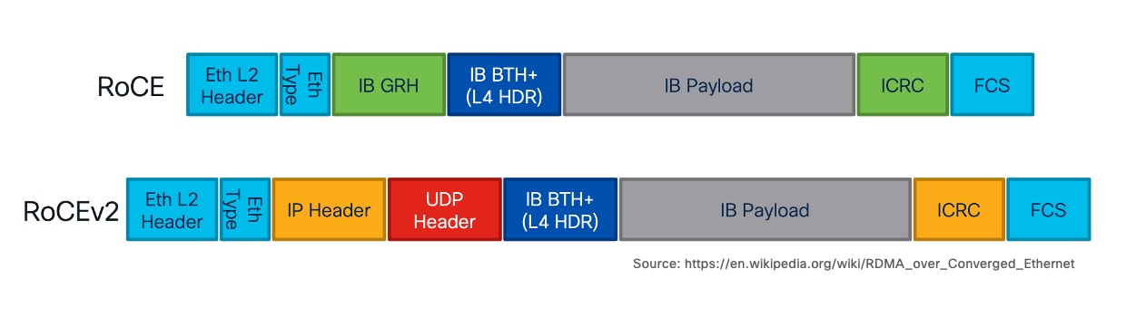
This encapsulation allows RoCEv2 traffic to be routed across standard IP networks, making it highly scalable for large AI clusters. RoCEv2 uses UDP destination port 4791 for this communication.
GPUDirect RDMA
GPUDirect RDMA is a NVIDIA technology that enables direct, high-speed data transfer between GPUs and other peripheral devices such as network interface cards (NICs) or storage. Across the backend fabric, RoCEv2 provides the network protocol for efficient data transfer, while GPUDirect RDMA enables GPU to leverage this protocol to send and receive data directly to and from the network.
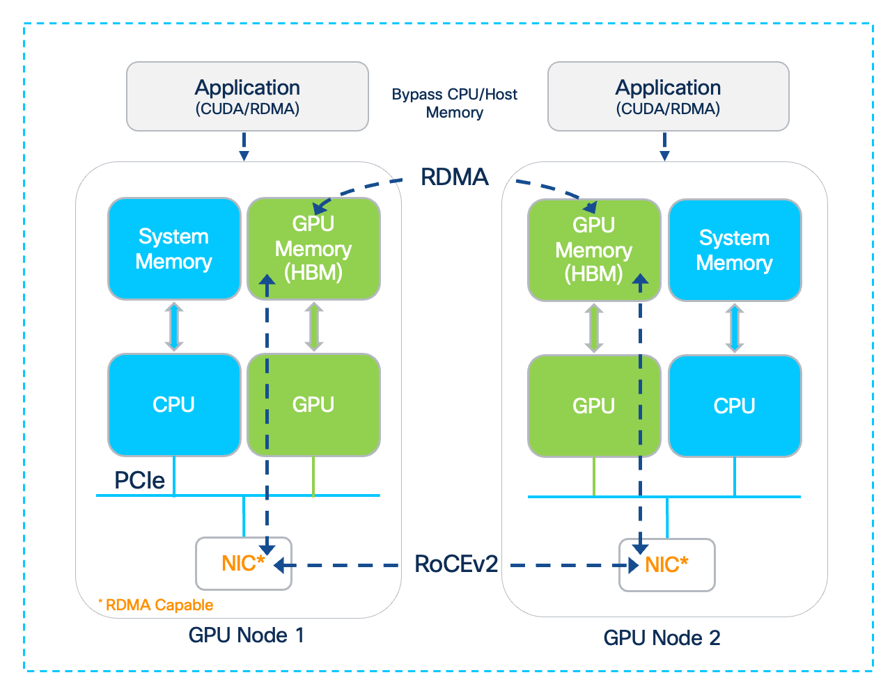
While GPUDirect RDMA enables direct data transfer between a GPU and other directly connected devices within a node, it is primarily designed for inter-node communication across nodes in a cluster. To achieve efficient inter-node GPU-to-GPU communication, GPUDirect RDMA establishes a direct data path between the GPU and the local RDMA-capable NIC, to enable RDMA operations across the backend fabric.
Note: GPUDirect RDMA to external storage systems is known as GPUDirect Storage (GDS). The connectivity to the storage system is through the frontend fabric; for detailed information go to section Frontend Fabric Design (North-South).
Without GPUDirect RDMA, the data transfers between a GPU and a network adapter would involve multiple copies through the CPU and system memory. GPUDirect RDMA bypasses this by enabling the NIC to directly read or write to the GPU's memory over the PCI Express (PCIe) bus. This direct communication between GPU and network adapter lowers the end-to-end latency, increases throughput (by maximizing available PCIe bandwidth), and frees up CPU cycles. This significantly improves the scalability of GPU clusters and performance of AI/ML training workloads distributed across multiple nodes.
This feature requires both the GPU and the NIC to support this capability.
GPU-to-GPU Connectivity
In a multi-node GPU cluster used for distributed AI training and fine-tuning, there can be multiple internal and external paths for GPU-to-GPU communication. The dense-GPU AI nodes will typically have a very high-speed internal path (for example, NVLink) for intra-node communication, as well as external connectivity through the E-W NICs and backend fabric for inter-node communication. In some cases, the internal path may also provide an alternate path for connecting to the external network. This section describes the various connectivity options for GPU-to-GPU communication in a multi-node AI cluster.
Connecting UCS GPU Node to Backend Fabric
Both Cisco UCS C885A and Cisco UCS C845A servers have dedicated backend (or E-W) NICs that the GPUs in the system can use for GPU-to-GPU communication across the backend fabric. For high-speed connectivity, the Cisco UCS C885A provides eight 1 x 400GbE NVIDIA BlueField-3 or ConnectX-7 NICs, one for each GPU, while the Cisco UCS C845A nodes provides up to four 1x 400GbE NICs, 1 NIC for every two GPUs deployed.
NVIDIA ConnectX-7 is a family of high-performance network Ethernet (and InfiniBand) adapters offering a range of speeds from 25GbE to 400GbE. These are PCIe Gen 5 x 16 adapters, providing key capabilities such as GPUDirect RDMA and 400GbE connectivity for GPU-to-GPU communication. They are available in Full-Height, Half-Length (FHHL) form-factor on Cisco UCS C845A M8 server and Half-Height, Half-Length (HHHL) form-factor on Cisco UCS C885A M8 server. The 100/200GbE version of this card is used as Frontend NICs – for more information, see Frontend Fabric Design (North-South).
NVIDIA BlueField-3 B3140H adapter is part of the NVIDIA BlueField-3 DPU (Data Processing Unit) family of adapters. These are also PCIe Gen 5 x 16 adapters, providing basic capabilities such as GPUDirect RDMA and 400GbE connectivity for GPU-to-GPU communication but also additional features as outline here. These are also available in FHHL form-factor on Cisco UCS C845A M8 server and HHHL on Cisco UCS C885A M8 server.
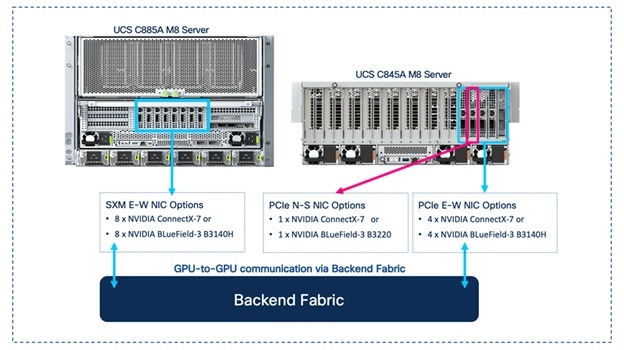
Note: BlueField-3 NIC may need to be deployed in NIC mode (as opposed to DPU mode) to maximize GPU performance (see the NIVIDIA documentation). This is a BIOS level change.
In the AI POD architecture, the UCS nodes are connected to upstream leaf switches in each Scale Unit Type by evenly distributing the ports to both switches – either by alternating or grouping the ports across the switches as shown in Figure 19.
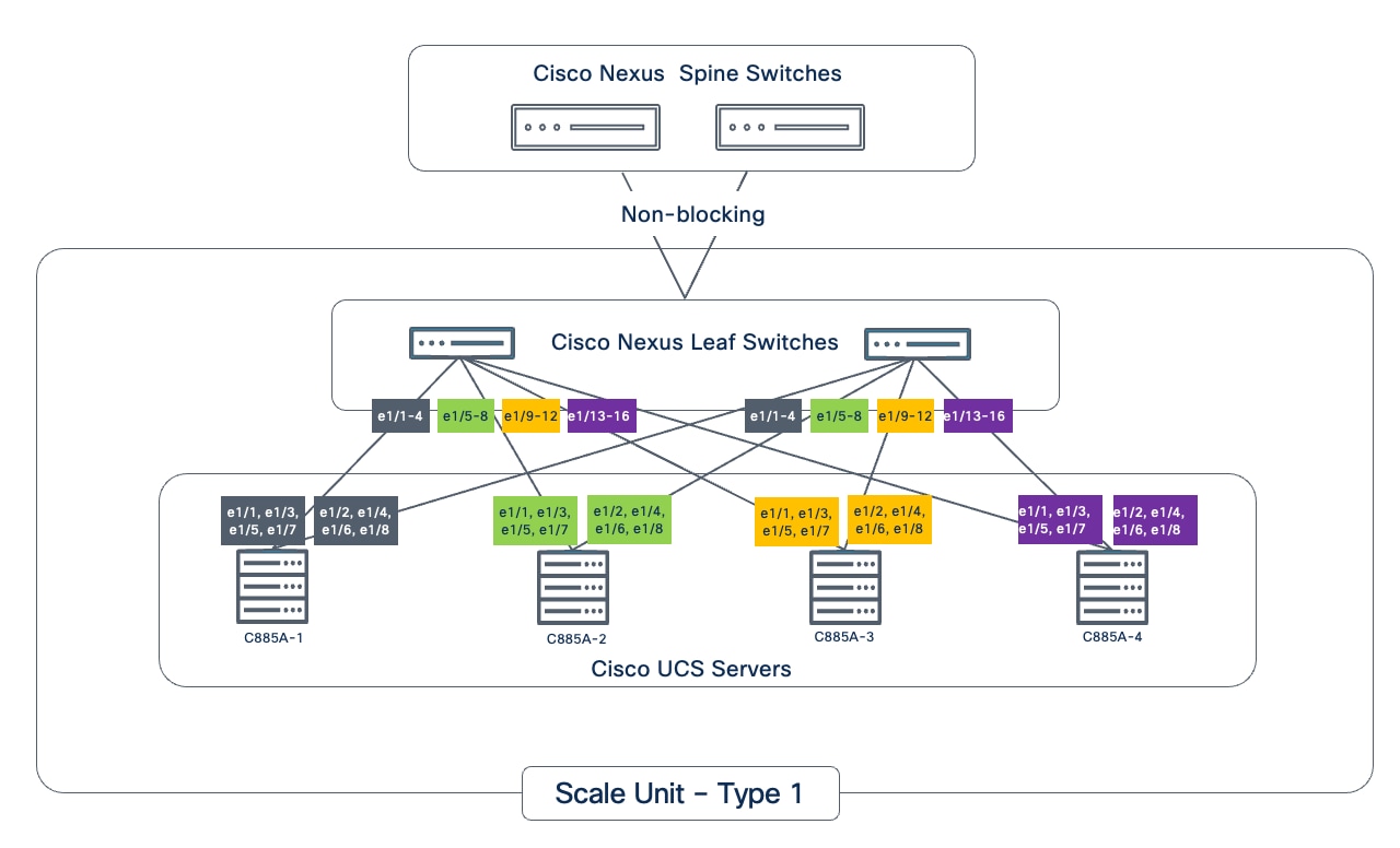
The backend NICs should be configured as untagged access interfaces with an IP addressing scheme that allows the GPUs allocated to a given workload to communicate with optimal performance. For multitenancy and other considerations, see section Multi-tenancy.
GPU-to-NIC Connectivity within a Cisco UCS Node
The internal PCIe connectivity between GPUs and NIC in the two UCS compute nodes are shown in the figures below. When GPUDirect RDMA is enabled, direct GPU to NIC data transfer will use this path.
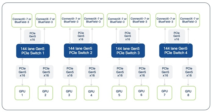
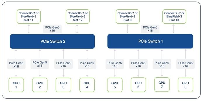
Note: On Cisco UCS C845A, the communication between GPUs located on different PCIe Switches will be routed through the CPU. 2-way and 4-way NVLink Bridges are not recommended across CPUs for this reason.
GPU-to-GPU Connectivity within a Cisco UCS Node
NVLink and PCIe provides direct, high-speed GPU-to-GPU communication within the same server.
This Cisco UCS C885A M8 server supports eight NVIDIA H200 SXM5 Tensor Core GPUs. Each of these GPUs is equipped with multiple NVLink ports, allowing it to connect to four fully non-blocking NVSwitches within the node.
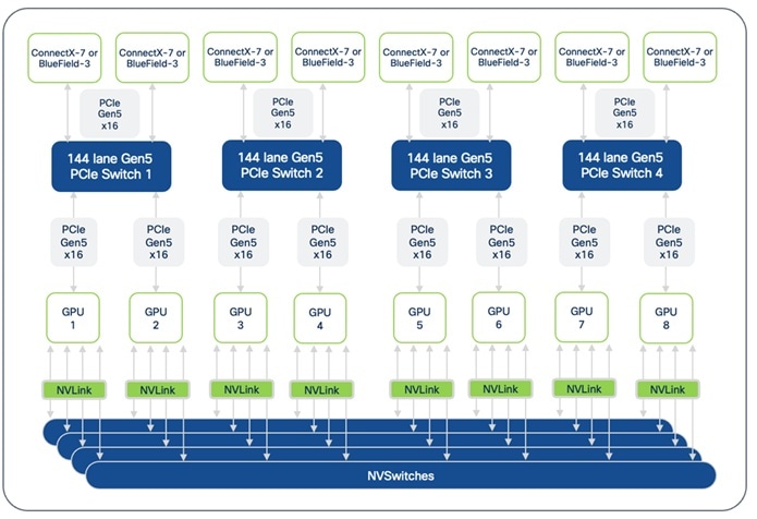
This configuration enables a high-speed NVLink bidirectional bandwidth of 900 GB/s between any pair of GPUs in the same node. For inter-node GPU-to-GPU connectivity, each H200 GPU is also connected to a dedicated NIC (such as a ConnectX-7) via a PCIe Gen5 x16 interface. These adapters are further connected through 144-lane Gen5 PCIe Switches, for GPU-to-GPU communication across nodes.
The Cisco UCS C845A M8 server supports up to 8 PCIe GPUs, with a minimum of 2 GPUs. The GPUs supported include L40S, RTX PRO 6000, H100 NVL and H200 NVL; the deployed GPUs must be of the same type. Cisco UCS C845A nodes support both 2-way and 4-way NVLink Bridges. When using 2-way bridges, the bridge must be fully populated with GPUs (minimum of 2 adjacent GPUs). Similarly, for 4-way bridges, a minimum of 4 adjacent GPUs are necessary per bridge.
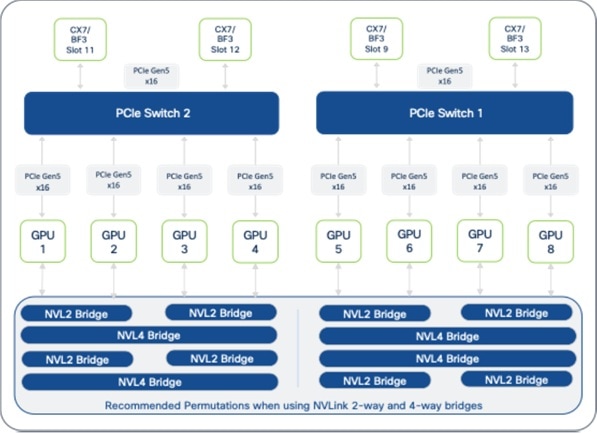
Note: GPU deployment on Cisco UCS C845A should start with slot 8 with subsequent GPUs (must be in pairs) placed in adjacent slots for a total of 2, 4, 6, or 8 GPUs per node.
GPU-to-GPU Connectivity across UCS GPU Nodes
A rail-optimized design is a specific network topology for connecting GPUs to the leaf switches, designed to provide low latency and high-bandwidth GPU-to-GPU communication across multiple GPU nodes. This design is critical for GPU-intensive workloads, such as large-scale distributed training of an LLM model.
In a rail-optimized topology, GPUs of the same rank across different nodes are connected using their E-W NICs to the same leaf switch. As nodes are added, this creates "rails" or GPUs of the same rank on the leaf or rail switch. This topology is optimized to maximize all-reduce performance, a critical collective communication operation used to synchronize gradients during distributed training. This direct, rail-aligned, single-hop connectivity ensures that communication between the same rank GPUs provides the lowest latency through the rail switch, ensuring optimal performance of collective communication operations like all-reduce.
Note: As model architectures evolve (for example, the Mixture of Experts model seen in more recent LLMs), the collective communication patterns may change. Also, the rail-optimized design above assumes that all GPUs are part of a single large workload, which may not be the case in enterprise deployments as previously discussed.
NVIDIA’s Enterprise Reference Architecture for enterprise deployments of up to 1024 GPU clusters, recommends a rail-optimized topology using at least two rail switches interconnected by direct links or through a spine or super-spine layer at higher scales.
Rail-optimized Design Options
Table 9 provides a summary comparison of the different rail-optimized design options available for use in the AI POD architecture. The design options are discussed in greater detail later in this section.
Table 9. Rail-optimized Design Options for 8-GPU, 8-NIC Nodes
| Feature / Design Type |
Rail-optimized (2-way) |
Rail-optimized (4-way) |
Rail-optimized (8-way) |
| Leaf/Rail Switches |
2 |
4 |
8 |
| Rails per Leaf Switch |
4 |
2 |
1 (dedicated leaf per rail) |
| Example Rail Distribution |
Switch 1: [1,3,5,7] Switch 2: [2,4,6,8] |
Switch 1: [1,5] Switch 2: [2,6] Switch 3: [3,7] Switch 4: [4,8] |
Switch 1: [1] … … Switch 8: [8] |
| GPU-to-GPU Communication |
Direct (single-hop) for Rail Groups on same switch (includes inter-rail) Using spine layer or PCIe × NVLink (PXN) for inter-rail |
Direct (single-hop) for Rail Groups on same switch (includes inter-rail) Using spine layer or PCIe × NVLink (PXN) for inter-rail |
Direct (single-hop) per rail and using spine layer (or) for inter-rail |
Rail-optimized Topology (2-way)
In the AI POD architecture, the UCS server GPUs and associated E-W NICs are typically distributed across the leaf switch pair in each Scale Unit Type. This configuration inherently results in a rail-optimized topology with multiple rails being mapped to the same leaf (or rail) switch.
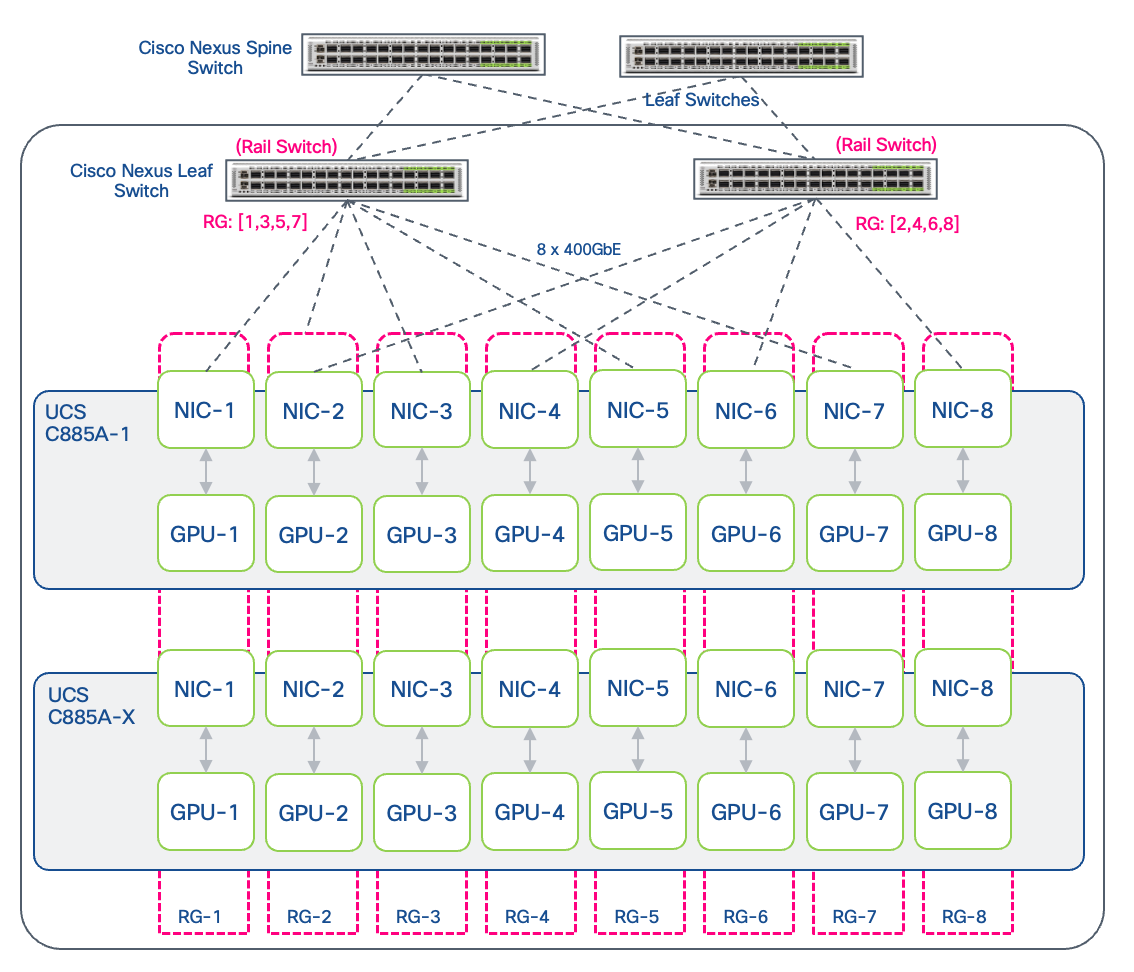
On a Cisco UCS C885A system with 8 GPUs and 8 E-W NICs (1:1 GPU:NIC ratio), the 2-way rail-optimized design will result in each of the leaf switches in the Scale Unit Type having four rails. The rails on the same switch form a Rail Group (RG). Depending on how the rails are distributed, this could result in the first rail switch connecting rails [1,3,5,7] and the second connecting [2,4,6,8] rails. Communication within a Rail Group on a given switch (for example, among the four rails on the first switch) is direct (single-hop) and does not require traffic to traverse the spine switches.
If NVIDIA PXN (PCIe × NVLink) is enabled, GPUs can also communicate across rails using NVLinks. PXN enables a GPU to communicate with another NIC on the same node through NVLink and then PCIe. For more information, see NVIDIA References at the end of this document.
Rail-optimized Topology (4-way)
At higher scales, as the number of leaf switches increases, the UCS servers in the AI POD design can also be connected optionally using a 4-way leaf design. In a 4-way design, the rail group consists of two rails per leaf switch across a total of four rail switches (representing 2 Scale Units), assuming an 8-GPU, 8 E-W NIC node such as the UCS C885A server. Depending on how the nodes are connected to the leaf switches, this may result in the first rail switch hosting rails [1,5], the second switch [2,6], the third [3,7], and the fourth [4,8]. NVIDIA PXN can also be leveraged in this design for efficient GPU communication across rails using NVLinks.
Rail-optimized (8-way)
The 8-way rail-optimized topology, commonly seen in large training clusters, uses eight leaf or rail switches to connect each GPU node. For 8-GPU, 8-NIC (E-W) compute servers (for example, Cisco UCS C885A), this design results in a dedicated leaf switch per rail. As GPU nodes are added to the cluster, they will use the same rail-aligned connectivity to connect the GPU NICs (E-W NICs) to the leaf switches in the backend fabric. The total number of GPUs of the same rank (same as number of nodes) that can be supported on a given rail switch (rail size), depends on the port-density of the rail switch, minus the ports used as uplinks. For non-blocking connectivity through the spines, leaf switches may need to reserve up to half their ports for uplink connectivity to the spines (to match the bandwidth on the downlinks). In this scenario, the rail size is equal to the number of downlink ports. In a rail-optimized design, the rack layout will need to be carefully evaluated due to the any-to-any connectivity between the NICs in each GPU server and the eight rail switches.
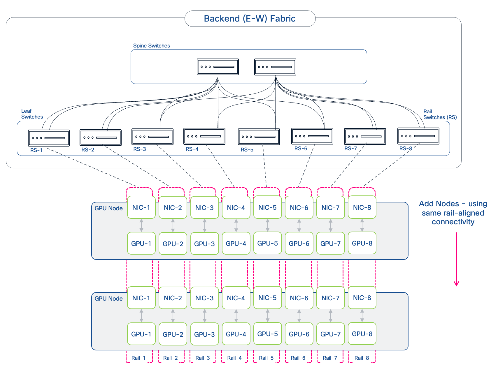
Similar to other rail-optimized designs, if NVIDIA PXN is enabled, GPUs can communicate across rails using NVLinks, leveraging the NVLink-to-PCIe path for efficient cross-rail communication.
Logical Architecture
The previous sections detailed the physical connectivity design and optimizations for a performant backend fabric, built using Cisco Nexus switches and Cisco UCS C8xx servers. This section builds on this and focuses on the higher-level logical architecture and design for the backend fabric within the AI POD architecture.
VXLAN BGP EVPN
The spine-leaf architecture, common in enterprise data center fabrics, is also leveraged in AI/ML fabrics as it provides a scalable, predictable, and consistent network design that can scale and support clusters of varying sizes within the same architecture. This topology can support either a pure Layer 3 or routed IP fabric (typically IP BGP) or an MP-BGP EVPN VXLAN fabric. The AI POD backend fabric uses MP-BGP EVPN VXLAN as it provides a flexible, a standards-based, scalable architecture, with the multi-tenancy that enterprises need. This architecture uses internet-scale MP-BGP in the control plane to advertise both Layer 2 (L2) MAC addresses and Layer 3 (L3) IP info. The EVPN control plane provides the network overlays (virtualization) to support multi-tenancy across an IP underlay. VXLAN provides the IP/UDP based data plane encapsulation for the overlay networks. A key benefit of this overall architecture is the flexible support of both Layer 2 extension and Layer 3 forwarding with network isolation, allowing enterprises to efficiently share the training fabric across teams and workloads, while also providing the flexibility to use either Layer 2 or Layer 3 for GPU-to-GPU communication.
The combination of spine-leaf topology with VXLAN BGP EVPN is also used in the front-end fabric and provides a consistent architecture across both fabrics in the AI POD architecture. This brings operational consistency and simplicity, which is important especially as you scale and grow your AI/ML clusters. For enterprises already using this architecture in their data center, there is the additional benefit of having a unified architecture across their AI and non-AI environments.
Multi-tenancy
Multi-tenancy in an enterprise environment enables multiple LOBs and teams (or tenants) to share a single AI cluster. This requires careful consideration of how many workloads will need to be deployed and how GPU resources will be efficiently distributed and allocated among them. The design must ensure optimal performance for each workload and provide a level of isolation appropriate for the enterprise’s specific security requirements, while ideally supporting on-demand scaling of GPU resources. Enterprises may also need additional orchestration tools to effectively manage this multi-tenant environment.
It is worth noting that trust boundaries within an enterprise differ from the strict isolation required in public cloud environments. Since enterprise tenants are typically internal teams within the same organization, the security model is likely to be less rigid than in a GPU-as-a-Service (GPUaaS) offering, where the tenants are external organizations. Because of this, enterprises may opt for a more flexible architecture that balances isolation with optimal use of resources, allowing for shared access to specific resources such as external storage systems.
Note: This CVD is not intended as a GPU-as-a-Service (GPUaaS) design, which involves additional considerations such as orchestration and management. This document focuses solely on the foundational aspects of building a multi-tenant AI infrastructure.
The foundation for multi-tenancy starts with the underlying infrastructure, spanning networking, compute to GPU and storage, followed by the OS/Kubernetes layer of the stack. The following sub-sections will discuss this in more detail.
Multi-tenancy at the Network Layer
Multi-tenancy with VXLAN BGP EVPN is achieved through several integrated mechanisms. VXLAN Network Identifiers (VNIs) provide Layer 2 isolation by creating unique network segments for each tenant's broadcast domain. For Layer 3, Virtual Routing and Forwarding (VRF) instances create separate, isolated routing tables for each tenant on the network devices (VTEPs), enabling different teams to use overlapping IP address schemes without conflict. MP-BGP uses Route Distinguishers (RDs) to keep tenant routes unique and Route Targets (RTs) to control which routes are shared, ensuring strict isolation between tenants.
However, for AI workloads, ensuring network performance for the different tenant workloads on the AI POD infrastructure is also a critical consideration. In the backend fabric, this is achieved through a non-blocking design that allows all GPUs utilized in the tenant workload to communicate at line-rate. Additionally, implementing load-balancing and QoS policies ensures fair usage and lossless, low latency RDMA communication as discussed in an earlier section.
The design supports two primary overlay types to support GPU-to-GPU communication within a tenant:
● A Layer 2 overlay extends a broadcast domain across the fabric. A VXLAN BGP EVPN fabric makes this highly efficient by providing features that minimize flooding, such as ARP suppression and using BGP EVPN Type 2 routes to distribute MAC address information. This eliminates the excessive broadcasting typically seen in traditional Layer 2 networks. GPU nodes communicate across the fabric as if they are on the same Layer 2 segment, without needing to route through a default gateway. In this case, all nodes, and specifically the E-W NICs on these nodes, must be in the same IP subnet.
● A Layer 3 overlay is used when routing between subnets is required within a tenant's environment. The recommended, scalable approach is Symmetric Integrated Routing and Bridging (IRB). In this model, both ingress and egress VTEPs participate in routing. It uses a dedicated Layer 3 VNI (L3VNI) for each tenant's VRF to handle inter-subnet traffic. This design is highly efficient as VTEPs only need to maintain routing information for directly connected subnets and the tenant's L3VNI. IP prefixes are distributed using BGP as EVPN Type 5 routes, which optimizes resource utilization on the network devices and simplifies configuration. To enable access to shared resources such as storage, route leaking can be used between tenant VRFs and a shared storage VRF.
Multi-tenancy at Compute and GPU Layer
For enterprises, multi-tenancy at the compute and GPU layer focuses on allocating GPU cluster resources to different teams or workloads. A key decision that enterprises must make is the granularity of this allocation. Specifically, should tenants be assigned entire servers (with all its GPUs) or should it also allow for partial allocation, where a subset of GPUs within a server are distributed across multiple tenants or workloads? Another consideration is fractional or sub-GPU level allocation such as MIG. However, this is typically not necessary in training environments, as training workloads typically require multiple GPUs across multiple nodes.
● Server-Level Allocation: The most straightforward approach is server-level allocation, where one or more servers are assigned to a single team (tenant) or workload. This approach is well-suited for performance-critical training jobs that can use an entire node's resources. For training and fine-tuning workloads, which can often scale to utilize all available resources, this model is highly effective. For Cisco UCS C885A and Cisco UCS C845A servers (assuming fully loaded), this would mean that a tenant will receive all 8 GPUs on the server. This also ensures that workloads running on these type of dense AI servers will use the high-speed, on-server interconnects such as NVLink since it is the best possible path for inter-GPU communication, and potentially across rails if NVIDIA’s PXN is enabled.
● GPU-Level Allocation: A more granular approach is GPU-level allocation, where groups of GPUs are assigned to different teams (tenants) or workloads. Allocation will likely be in multiples of two (for example, 2, 4, 8 GPUs) rather than on a single-GPU basis. In dense GPU servers, this could result in different GPUs from the same server being allocated to different tenants (or workloads). In this scenario, simply putting the GPU NICs into different VRFs is not sufficient. If the GPUs in these servers are interconnected by high-speed NVLinks that allow direct peer-to-peer access, additional mechanisms will need to be in place to allow GPUs in the same tenant (or workload) to communicate, while blocking GPUs on different tenants or workloads.
Enterprises will need to balance operational simplicity and performance of server-level allocation with resource efficiency and granularity of GPU-level allocation when deciding on the approach that best suits their organization’s needs. In a dedicated training and fine-tuning cluster, the decision is often simpler: server-level allocation allows all jobs, however small, to be accelerated, resulting in a shorter JCT. However, in a mixed or hybrid environment that includes inferencing workloads, right-sizing tenant workloads while ensuring efficient use of GPU resources can be more challenging.
Multi-tenancy with Kubernetes
In modern, cloud-native deployments, Kubernetes (K8s) has become the de facto standard for deploying, scaling, and overall management of containerized applications like AI/ML workloads. All AI workloads, from large-scale distributed training to smaller fine-tuning tasks, can run as containers managed by Kubernetes.
To securely share an AI cluster among multiple tenants and workloads, Kubernetes provides several mechanisms for creating isolated multi-tenant environments. These include:
● Namespaces are the primary mechanism in Kubernetes for providing logical isolation within a single cluster. Each tenant is assigned one or more dedicated namespaces, which act as a virtual boundary for all their resources, including pods, services, and configurations.
● Role-Based Access Control (RBAC) policies are used to grant users, teams and service accounts access to only their assigned namespaces and resources, ensuring they can only access resources they are explicitly authorized to use.
● Resource Quotas and Limit Ranges enforce resource consumption limits to prevent any single tenant or workload from monopolizing shared resources. Resource Quotas can set a hard limit on the total number of GPUs, CPU cores, and memory a tenant or namespace can consume across all their workloads, ensuring fair resource distribution and preventing any single tenant from monopolizing the cluster. Limit Ranges, on the other hand, specify similar range constraints but for individual pods within a namespace.
● Network Policies provide granular control over traffic flow between pods and namespaces, extending the network-level isolation provided by VRFs to the compute/OS layer. For example, a deny-all policy can be deployed to block all cross-namespace traffic. This will require a compatible Container Network Interface (CNI) plugin to implement restricted communications between pods and namespaces.
● Linux cgroups provide a Linux kernel mechanism for resource isolation. Kubernetes leverages cgroups to enforce the CPU and memory limits specified for each container, ensuring that a tenant's workload cannot consume more than its allocated resources and preventing "noisy neighbor" issues on a shared node.
● Pod Security features to enforce isolation between tenants and implement security best practices such as restricting a container from running in privileged mode to prevent access to other workloads. Red Hat OpenShift provides Security Context Constraints to control pod privileges for the workloads running on OpenShift as described here.
● Node Isolation using Taints and Tolerations provides some level of isolation by allocating nodes and GPUs to certain tenants and in a mixed or hybrid environment, to restrict non-AI workloads from getting deployed on GPU nodes.
● KubeVirt can be used to provide strong hypervisor-level isolation between tenants that allows a single node to be partitioned across multiple tenants by supporting multiple K8s clusters on virtual machines running on the same physical node.
● Hosted Control Planes in OpenShift can also be used in scenarios requiring stronger isolation by providing different tenants their own control plane while still sharing control plane hardware. In this scenario, each tenant would have their own dedicated worker nodes and cluster, but the control plane for their cluster will run on shared infrastructure, making it an efficient and secure approach to providing tenant K8s clusters at scale. For more information on Red Hat OpenShift Hosted Control Planes, see here.
For Server-Level Allocation, Kubernetes can use mechanisms like node labels, taints, tolerations, and hardware profiles to segment resources. For example, a node can be labeled and "tainted" as belonging to a specific tenant. Only workloads from that tenant with the corresponding "toleration" will be scheduled on that node, effectively dedicating the entire server.
For GPU-Level Allocation, Kubernetes can schedule pods requesting a specific number of GPUs onto nodes with available capacity. Critically, it enforces the isolation required to prevent GPU-to-GPU access via NVLink. When a pod is assigned specific GPUs, the underlying Linux OS uses cgroups to restrict the container's visibility to only those physical devices, effectively preventing the NVLink peer-to-peer communication between GPUs allocated to different tenants residing on the same server. The orchestrator then injects the CUDA_VISIBLE_DEVICES environment variable into the container, ensuring the CUDA runtime and the application can only see and use the GPUs allocated to them. This combination of OS-level cgroups and CUDA environment variables provides the necessary host-level isolation.
IP Addressing
IP addressing plan for the backend fabric is essential for the scalability and manageability of the GPU cluster. The addressing will need to support both the physical network infrastructure (the underlay) and the logical tenant networks (the overlay). In enterprise deployments, the AI training clusters are relatively small, typically less than 1024 GPUs compared to hyperscalers that use thousands or tens of thousands of GPUs. These clusters are also isolated environments with no outside connectivity to other networks, either within the enterprise or externally so the IP addressing can be a private RFC 1918 block. By using MP-BGP VXLAN in the design, the cluster can be shared among teams (tenants) with VRFs providing network isolation between tenant workloads.
The VXLAN EVPN underlay network provides the IP reachability between the Cisco Nexus switches in a Spine-Leaf topology. The addressing scheme is straightforward, static, and completely independent of any tenant workloads. An RFC 1918 block (or other IP ranges) can be used for this addressing, typically /30 for the point-to-point links between switches and /32 for loopbacks. If this remains a completely isolated fabric, any IP addressing range can be used, and this addressing can be replicated across other AI backend fabrics that an enterprise may deploy.
Table 10 provides a sample addressing plan based on the provided Nexus Dashboard template settings.
Table 10. Backend Fabric: Underlay IP Addressing Example
| Connectivity / Route Type |
IP range |
| Loopbacks: Underlay Routing |
20.2.0.0/22 |
| Loopbacks: Underlay VTEP |
20.3.0.0/22 |
| Loopbacks: Underlay RP |
20.254.254.0/24 |
| Underlay Interface Addressing |
20.4.0.0/16 (/30s assigned) |
Note: Default ND allocation uses 10.x.y.z. Masks are kept the same though it could be much less. These settings can be modified in the AI/ML fabric deployment template if necessary.
The VXLAN EVPN overlay network is where the enterprise training workloads run. The overlay network should be allocated a single, large IP block based on the maximum number of GPU endpoints the cluster is expected to grow to.
The MP-BGP EVPN allows the use of overlapping address space across tenant VRFs, but in a dynamic enterprise environment, this provides less flexibility and makes it harder to manage and troubleshoot.
To support multi-tenancy, the larger, cluster-wide IP block can be segmented into smaller subnets as outlined below. In a multi-tenant environment, the addressing model should support the chosen GPU allocation granularity.
● Single-Tenant with Single/Multiple Large Workload(s): The single tenant, single workload is the simplest model in an enterprise environment, typically used when the entire cluster is dedicated to a single tenant for a very large, cluster-wide training job. In this scenario, a single, large IP subnet (for example, a /21) is allocated for the cluster. The subnet should provide enough IP addresses for all GPU NICs across all servers in the cluster. Smaller clusters can use Layer 2 overlay across the fabric. Addressing should account for Gateway IPs if Layer 3 forwarding is used in the overlay.
If the tenant has multiple workloads, the larger IP block can be segmented to fit the needs of the individual workloads. Each workload can use either Layer 2 (for smaller workloads) or Layer 3 forwarding in the overlay for GPU-to-GPU communication.
● Per-Tenant Subnet Model: Each tenant is assigned a dedicated IP subnet from the main block based on the number of GPUs allocated to the tenant, with room for growth. The assigned block can be a single network segment for a single workload or further divided it into multiple subnets for multiple workloads within the same tenant VRF. When the tenant cluster expands, additional subnets can be allocated if the current allocation cannot meet the need. If the tenant has GPUs that require reachability across multiple subnets, (workload that spans resources in both subnets), a Layer 3 overlay will be necessary to route between the subnets. Otherwise, each workload can use either Layer 2 (for smaller workloads) or Layer 3 forwarding in the overlay for GPU-to-GPU communication.
Note: When using Layer 2 forwarding in the overlay, it is important to not exceed the ARP cached for the OS running on the GPU nodes.
A sample addressing for an enterprise AI cluster with an expected maximum scale of 1024 GPUs is shown in Table 11.
Example: IP addressing scheme for scaling the GPU cluster from 32 GPUs to 1024 GPUs in increments of 32 GPUs (Scale Unit – Type 1). For 1024 GPUs, a minimal IP subnet allocation of /21 of higher is required, accounting for all GPU (E-W) NICs, Gateway IPs when VRFs with L3 overlays are used, and room for growth.
● Cluster IP Block: 10.11.0.0/16 (based on maximum expected growth for the GPU cluster)
● Number of IP Addresses required for each UCS C885A (E-W) NICs: Same as the number of GPUs
● Number of IP Addresses required for each Cisco UCS C845A (E-W) NICs: Half the number of GPUs
For each table row below:
● Each block can be further segmented to support multiple workloads and teams (tenants)
● Tenants can be allocated a smaller subnet or the whole block depending on the GPUs allocated
● Each block has room for growth – fabric can be expanded by adding scale units, with GPUs residing anywhere in the fabric with layer 2 or layer 3 connectivity between GPUs in the same VRF. Note that physical location of the newly added GPUs in the spine-leaf topology will determine the latency for GPU-to-GPU communication if the workload spans both new and old GPUs.
Table 11. Backend Fabric: Overlay IP Addressing Example
| Scale Unit – Type 1 |
GPU Cluster Size (GPUs) |
Cisco UCS C885A: IP range (E-W) GPU (GPU:NIC > 1:1) IP Block: 32 |
Cisco UCS C845A: IP range (E-W) GPU (GPU:NIC > 2:1) IP Block: 16 |
| 1 SU |
0 - 32 GPUs |
10.11.0.0/26 |
10.11.0.0/27 |
| 2 SU |
32 - 64 GPUs |
10.11.0.32/26 |
10.11.0.16/27 |
| 4 SU |
64 - 128 GPUs |
10.11.0.[64 | 96]/26 |
10.11.0.[32 | 48]/27 |
| 8 SU |
128 - 256 GPUs |
10.11.0.[128 | … | 224]/26 |
10.11.0.[64 | … |112]/27 |
| 16 SU |
256 - 512 GPUs |
10.11.1.0/26 |
10.11.1.[128 | … | 248]/27 |
| 32 SU |
512 - 1024 GPUs |
10.11.[2–3].0/26 |
10.11.1.0/27 |
The above addressing scheme is for a starting cluster of 32 GPU endpoints (Scale Unit – Type 1) that can be scaled to support up to 1024 GPUs by adding Scale Units (32 GPUs). This approach can be used to define an IP addressing scheme for Scale Unit - Type 2 and Scale Unit - Type 3. There are other valid approaches to defining the IP addressing for a cluster – Enterprises can opt for an approach that best fits their needs.
The initial allocation and sizing of subnets for a given tenant should be based on the number of GPU endpoints they are expected to use concurrently and factor in future growth and scale by allocating slightly larger subnet blocks.
Frontend Fabric Design (North-South)
The Frontend Fabric serves as a multi-purpose network in an AI training and fine-tuning environment, providing key support services to orchestrate and manage the GPU infrastructure and the workloads running on them. In a hybrid deployment, it also serves as the inferencing network that users use to access the ML model running on the GPU cluster. Since the backend fabric is isolated with no external connectivity, the frontend fabric also serves as a gateway to the GPU cluster. It provides connectivity for storage access, cluster management, and user (including inference) access. In contrast to the backend fabric, which is dedicated exclusively to high-performance GPU-to-GPU communication, the design of the frontend fabric must be flexible and scale to meet the needs of the GPU cluster, ideally operational simplicity, and consistency. The frontend fabric in the AI POD architecture is designed just to do that as we will see in the upcoming discussion. Enterprise can also deploy a dedicated Frontend Fabric as outlined in this document or use their existing DC fabric especially when it is a Cisco Nexus based fabric as long as it can meet the requirements to support a training GPU cluster at scale.
Key Requirements
The frontend fabric typically includes a management cluster with compute nodes to host management and control plane components for the cluster. Some of the services that the frontend fabric provides access to are:
● PXE boot server for remote booting of OS. When using an Ubuntu OS stack with NVIDIA’s Base Command Manager Essentials (BCME) for management, PXE booting of the servers is through this interface.
● Access to IP network services such as DNS and DHCP.
● Workload orchestration and management to initiate training and fine-tuning on the cluster. When using Kubernetes, this include control nodes with UCS C885A and C845A nodes as worker nodes in the same cluster. When running Ubuntu OS stack with NVIDIA’s BCME, this could be either SLURM or control plane nodes for Vanilla K8s nodes.
● Access to highly available shared storage hosted on external storage systems. Training and checkpoint data used in training and fine-tuning is stored here.
● Provides an out-of-band path for NVIDIA’s NCCL and AMD’s RCCL.
● Other support tools required to manage and monitor the GPU cluster.
Network Fabric Design
The frontend (North-South) fabric in the AI POD architecture is a two-tier, spine-leaf (Clos) topology using Cisco Nexus 9000 series switches, similar to the backend fabric design. This design consistency between the fabrics makes it operationally simpler to manage the two AI fabrics, especially at scale. Using Nexus Dashboard to uniformly manage the two fabric brings significant operational simplicity and ease.
As discussed in the backend fabric section, the spine-leaf architecture provides several inherent benefits, one of which is the ability to expand by adding leaf or spine switch pairs as needed. As such, a spine-leaf design using the same Nexus Dashboard as the one used to manage the backend fabric is the recommended design in the AI POD architecture even for small starter deployments.
Figure 26 shows a high-level topology of the back-end fabric.
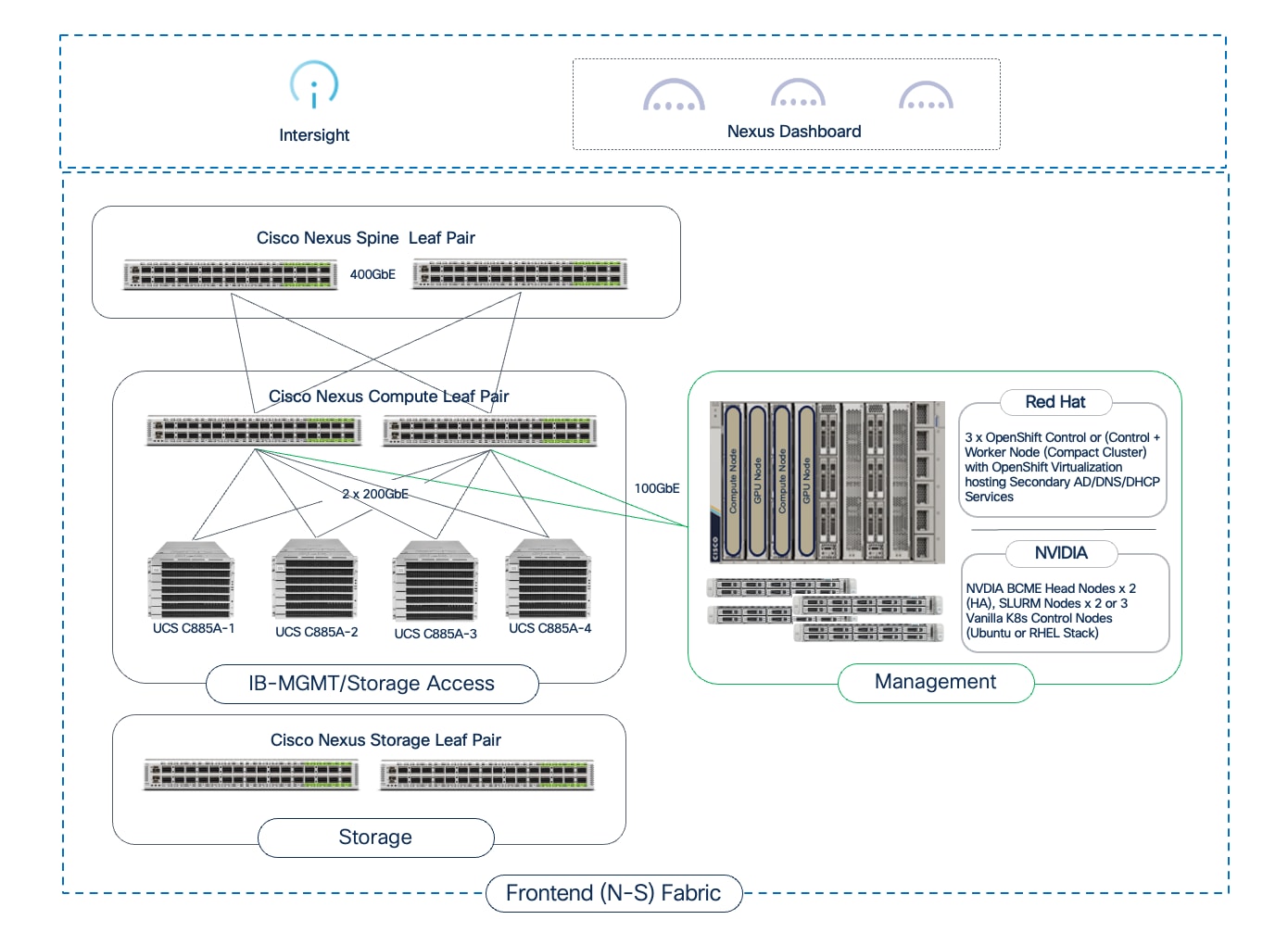
A key requirement of the frontend fabric is that it must provide sufficient bandwidth to prevent storage I/O from becoming a bottleneck. NVIDIA’s Enterprise Reference Architecture recommends a minimum bandwidth of 12.5Gbps of storage bandwidth per GPU. For an 8-GPU server like the Cisco UCS C885A, this translates to a minimum of 100 Gbps of dedicated storage bandwidth. To meet this with other considerations factored in, each server could be connected to the frontend fabric using:
● Same NIC for all traffic (management, control, user, inference, storage, and so on). This requires VLAN trunking with bonding to provide high availability. If Link Aggregation Control Protocol (LACP) bonding is used, and the FE NIC is a NVIDIA BlueField-3 DPU (B3220), the NICs will need to be in NIC mode to support LACP bonding. Also, if using PXE boot, some additional configuration will be necessary to support this so that the server can produce an IP address, load OS before the LACP bond comes up. PXE boot will fail otherwise.
● Dedicated NIC for storage. This provides higher performance and scale, and particularly important in a hybrid deployment with inferencing traffic adding to the load on the frontend NIC.
Note: Cisco UCS C885A supports two NICs but only one FE NIC is supported on the Cisco UCS C845A server.
In addition to storage traffic, if the node is deployed in a hybrid (training + inferencing) environment, NVIDIA Enterprise Reference Architecture recommends a minimum bandwidth of 25Gbps of bandwidth per GPU. This translates to 200Gbps of FE bandwidth when using a Cisco UCS C885A or Cisco UCS C845A with 8 GPUs. In this scenario, a dedicated NIC for storage is worth considering.
Optimizations and Technologies used in the FE fabric
Over-subscription
Unlike the non-blocking backend fabric, the frontend fabric can be oversubscribed, as the traffic patterns are more varied and less stringent than the GPU-to-GPU collective communication traffic. A 4:1 over-subscription is a safe starting point in the frontend fabric, and if there is monitoring is in place to gauge link utilization, additional links can be added between leaf and spine switches as needed.
Quality of Service
When storage traffic using RDMA (RoCEv2) shares the same fabric as other best-effort traffic (as in the Combined Traffic Model), a robust QoS policy is mandatory. Unlike the backend fabric where nearly all traffic is lossless RDMA, the frontend fabric is mixed. Without QoS, a burst of management or user traffic could cause packet drops, which is catastrophic for the lossless requirements of RoCEv2.
The QoS policy must use PFC to create a lossless "lane" for RoCEv2 traffic, preventing drops for storage I/O, while allowing other traffic types to share the same physical links in a best-effort manner.
GPUDirect Storage
GPUDirect Storage (GDS) is an NVIDIA technology designed to create a direct, high-speed data path between storage devices and GPU memory to keep powerful GPUs consistently supplied with data and not allow slow I/O operations from becoming a bottleneck in loading data into the GPUs. Without GDS, moving data from storage to a GPU involved multiple steps and copies: data is first read from storage into the CPU's system memory, and then copied from system memory to the GPU's memory. This process consumes valuable CPU cycles and limits overall data bandwidth.
GPUDirect Storage can provide significant benefits in AI/ML training by reducing latency, increasing throughput, and freeing up CPU from managing data movement. Ultimately, GDS improves the scalability and performance of AI/ML training by ensuring GPUs are not starved for data.
GPUDirect Storage is a data path optimization, enabling GPUs to have a more direct path to storage. It is commonly discussed in the context of the frontend fabric because the connectivity to the storage system is typically through this fabric. While GDS provides the mechanism for direct data transfer to the GPU's memory, it leverages the connectivity provided by this frontend fabric to reach the storage.
The storage system and design is a critical component of the AI training and fine-tuning infrastructure. AI workloads require high-performance, scalable, and secure access to storage to read large training datasets and to write model checkpoints, logging, and other artifacts during the training process. A key storage requirement is for very high-throughput sequential reads, as massive datasets may need to be loaded into GPU memory at the beginning of each training epoch. In an enterprise deployment, storage is typically a shared resource, and each team (or tenant) will require dedicated, isolated storage for their data.
For high-performance access to storage, several key design aspects must be considered to ensure storage is not a bottleneck:
● Bandwidth Requirements: NVIDIA’s Enterprise Reference Architecture recommends a minimum of 12.5 Gbps of network bandwidth per GPU for storage access. For an 8-GPU server such as the Cisco UCS C885A, this translates to a minimum of 100 Gbps of dedicated storage bandwidth. Therefore, a 100GbE or faster NIC should be used for storage traffic.
● MTU: Ensure MTU of 9000 is supported end-to-end from compute to storage.
● Low Latency Storage Access (RDMA and GPUDirect): In an AI training deployment, two key technologies, NFS over RDMA and GPUDirect Storage work together to meet bandwidth and latency requirements for storage. By using RoCEv2 protocol, data can be transferred directly between the storage system and the GPU servers by leveraging GPUDirect Storage. GDS provides a direct data path between storage network and GPU memory. Without it, data must be copied from the storage network to the server's system memory (CPU RAM) before being copied to the GPU's memory. GPUDirect Storage eliminates this extra copy by allowing the storage NIC to directly access the GPU memory to send data over the network to remote storage system. This dramatically lowers I/O latency and increases the bandwidth, ensuring that storage is not a bottleneck and that GPUs are not waiting on data during the training process. On PCIe-based servers, ensure server PCIe placement of NICs relative to GPUs to prevent cross-socket transfers, which degrade GDS throughput
● Dedicated Storage NIC: For higher scale and performance, a second network adapter, dedicated for storage access, can be deployed on the Cisco UCS C885A node. This cannot be done on the Cisco UCS C845A as it only supports one frontend NIC currently. This prevents storage I/O from contending with other traffic on the frontend NIC that are being used for management, control, and other traffic. Use separate VLAN and QoS class for storage RDMA traffic when possible.
● Dedicated Storage Leafs in the Frontend Fabric: For larger-scale deployments or when using high-performance SDS like VAST Data, it is a best practice to use dedicated storage leaf switches. In this topology, the storage nodes connect to their own set of leaf switches, which then connect to the spines. This isolates all storage traffic from the compute fabric, preventing congestion and allowing the storage network to be scaled independently.
In AI training fabrics, multiple storage tiers are typically used to meet the different storage requirements and to balance performance and cost, at scale.
● High-Performance File Storage
A centralized, high-performance file system (typically NFS over RDMA) is used as the primary storage in AI training environments. It allows training clusters to mount NFS shares and access (or read) training data concurrently. Tenant isolation is achieved by assigning dedicated directories or export paths, with access controlled using permissions and network rules.
● S3-Compatible Object Store
A scalable object storage system is used for long-term storage of raw datasets, models, and artifacts. Tenant isolation is provided by assigning dedicated buckets with IAM-style access policies.
When using Kubernetes in a training environment, the storage system must seamlessly integrate with Kubernetes to allow workloads to consume storage resources dynamically and persistently. Kubernetes provides Container Storage Interface (CSI) which is a standardized mechanism for K8s clusters to integrate with storage. A CSI driver for your chosen storage system (for example, NFS) is deployed in the Kubernetes cluster. Tenants can then request storage for their workloads by creating Persistent Volume Claims (PVCs). Kubernetes uses the CSI driver to automatically provision a Persistent Volume (PV) from the correct storage backend and mount it into the tenant's pods, abstracting the underlying storage details from the end-user.
This combination of high-performance connectivity design, tiered storage, multi-tenancy controls, and Kubernetes integration is used in the AI POD architecture to deliver flexible storage options for an AI training and fine-tuning environment. The AI POD CVD will validate storage from partners such as NetApp, Pure Storage, and VAST Data meet these requirements.
With the foundational infrastructure components (compute, networking, storage) in place, the software stack is next in the AI infrastructure stack. The software stack consists of the foundational software components running on the UCS GPU nodes that create a functional, performant environment for AI training and fine-tuning workloads. The ML frameworks and libraries that data scientists use to build, train and customize AI models run on top of this foundational stack. The generic layers of the software stack for AI workloads are shown in Figure 27.
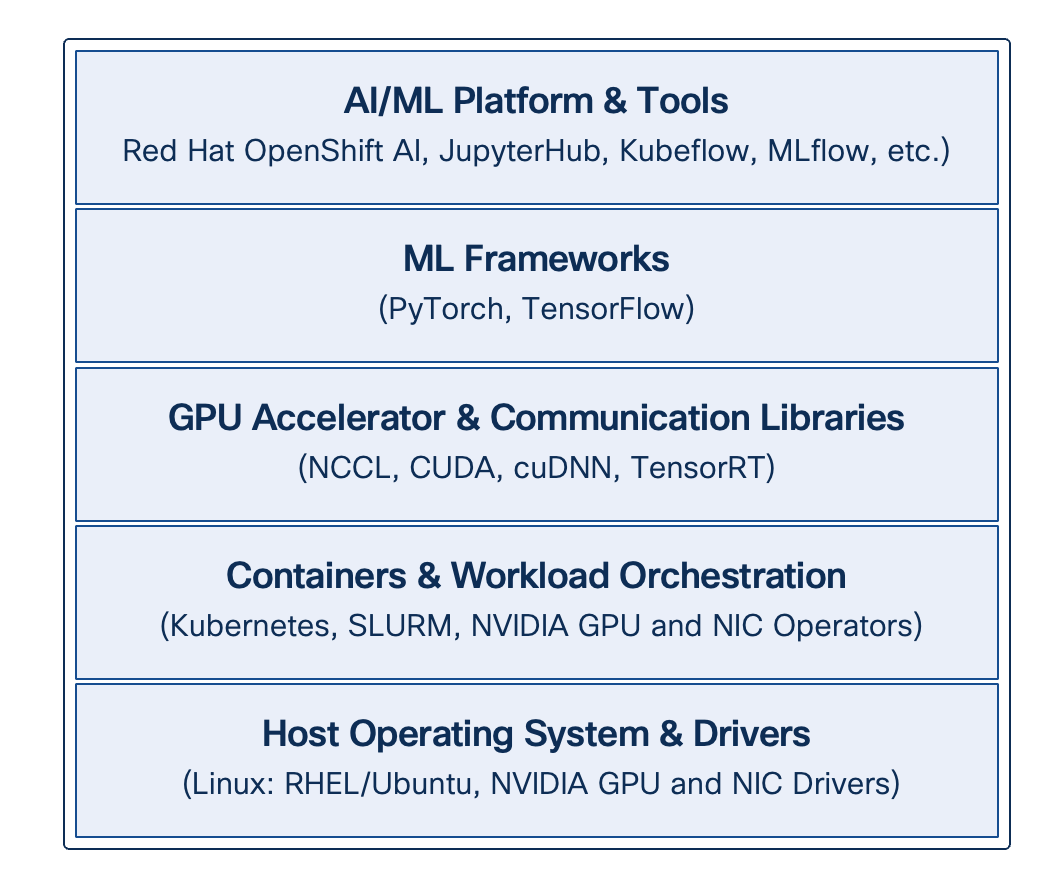
● Operating System
The base software stack is the Linux operating system that will run on each UCS GPU server. Common choices in AI training environments are Ubuntu or Red Hat Enterprise Linux (RHEL). The OS must be optimized for high-performance workloads, which may include tuning kernel parameters for networking and resource limits. For a complete list of the operating systems supported on the UCS GPU nodes, see the UCS Hardware Compatibility List (HCL) tool.
● Workload Orchestration
Kubernetes or SLURM (in Ubuntu deployments) can be used for workload scheduling and orchestration. In a Kubernetes environment, NVIDIA provides various K8s Operators to automate the deployment and configuration of the NVIDIA NIC and GPU drivers and related components.
● NVIDIA Collective Communications Library (NCCL)
For distributed training jobs in a training cluster spanning multiple GPUs and nodes, the NVIDIA Collective Communications Library (NCCL) is critical. NCCL provides highly optimized routines for collective communication operations (for example, All-Reduce). It is designed to leverage high-speed interconnects like NVLink for intra-node communication and the high-performance backend fabric for inter-node communication, ensuring that data synchronization between GPUs is performant. ML frameworks like PyTorch and TensorFlow use NCCL to enable distributed training across a multi-node GPU cluster.
● ML Frameworks
At the top of this foundational stack are the machine learning frameworks that data scientists use to build and train models, such as PyTorch and TensorFlow. These frameworks provide the high-level APIs for defining neural networks and training loops, while relying on the lower-level components like CUDA, cuDNN, and NCCL to execute the operations efficiently on the GPU hardware.
● NVIDIA AI Enterprise
NVAIE is not a single component in the stack, but rather a comprehensive suite of software that spans multiple layers of the stack. It includes certified NVIDIA GPU and NIC drivers, CUDA, cuDNN, various AI frameworks, and other NVIDIA tools. Instead of assembling and validating these components individually, NVAIE provides a fully supported, enterprise-class suite of software, optimized to run on NVIDIA hardware (GPUs, NICs).
Figure 28 shows the common software stacks in the AI POD architecture, followed by more detailed stacks from NVIDIA and Red Hat for an AI POD training deployment.
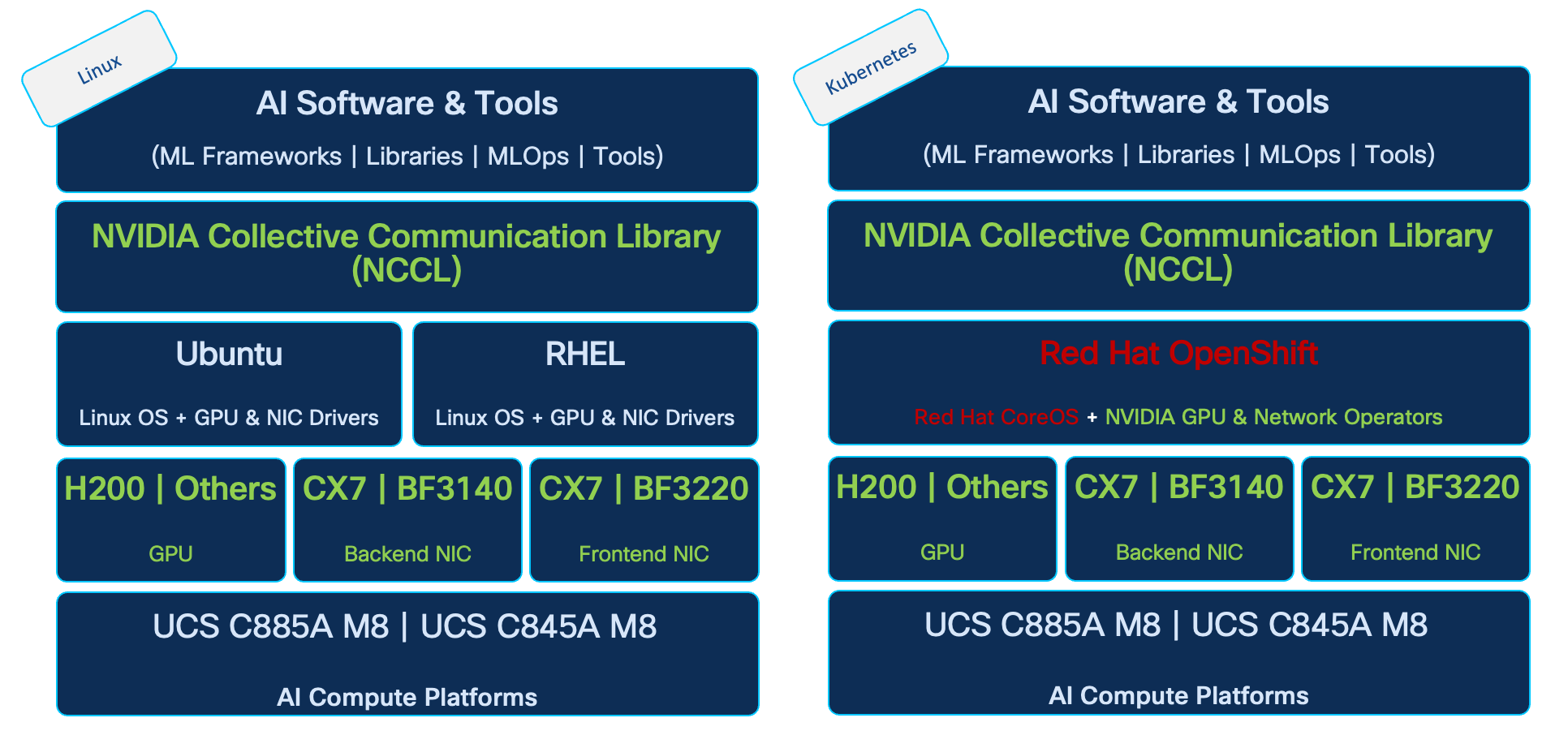
Figure 29 shows an extension of the above stacks from (1) NVIDIA using BCME and (2) Red Hat using Red Hat OpenShift and OpenShift AI.
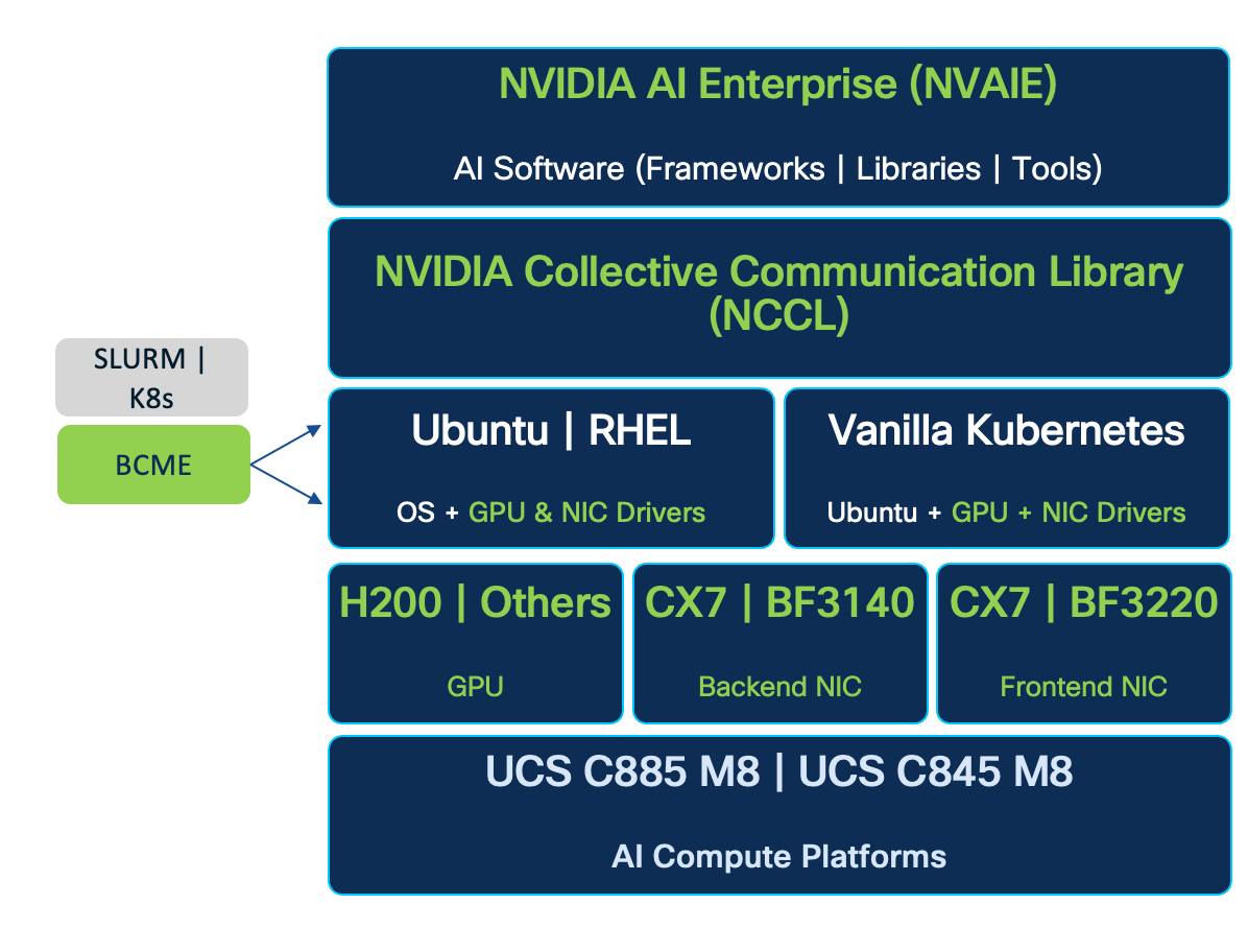
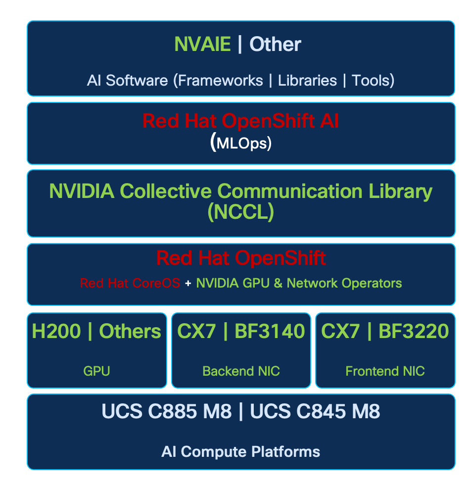
MLOps using Red Hat OpenShift AI
Red Hat OpenShift AI an enterprise-grade MLOps platform built on Red Hat OpenShift Container Platform. It enables data scientists, developers, and IT teams to manage the complete AI/ML lifecycle—from data exploration and model development to training, serving, and monitoring—in a secure, scalable, and hybrid-cloud environment. It includes AI safety guardrails for LLMs, expanded support for large model deployment, distributed inference with llm-d, and a modular toolkit for model customization.
Key features include:
● Data Science Projects: Dedicated namespaces for team isolation, collaboration, and resource governance, with enhanced hardware provisioning.
● Workbenches: Customizable Jupyter-based environments for interactive development, supporting secure custom images and data connections.
● Data Science Pipelines: Kubeflow Pipelines (KFP)-powered workflows for automating data preparation, training, evaluation, and deployment, with versioned runs and artifact tracking.
● Model Serving: KServe-based inference supporting single-model and multi-model runtimes, with optimizations for LLMs via vLLM, distributed scaling with llm-d, resource settings, and RAG stacks using LlamaStack.
● Distributed Workloads: Ray integration for scaling training and processing, featuring GPU-aware auto-scaling and monitoring for larger datasets.
● Resource Management: Advanced hardware profiles, Kueue for job queuing, accelerator allocation, user quotas, and telemetry configuration.
● Model Registry: Versioned storage and management with RBAC-secured access and monitoring.
● Monitoring and Governance: Tools for model performance, bias detection, compliance auditing, and AI safety with guardrails and detectors.
● Integrations: S3-compatible storage, databases, Git, MLflow, and emerging capabilities like feature stores.
This Kubernetes-native stack ensures reproducibility, inherits OpenShift's security, and supports regulated industries with focus on LLM safety, efficient scaling, and modular customization.
Architecture
Red Hat OpenShift AI deploys as an operator-managed addon on OpenShift 4.x clusters, using Kubernetes primitives for modularity. Components are enabled independently via custom resources, emphasizing scalability and integration.
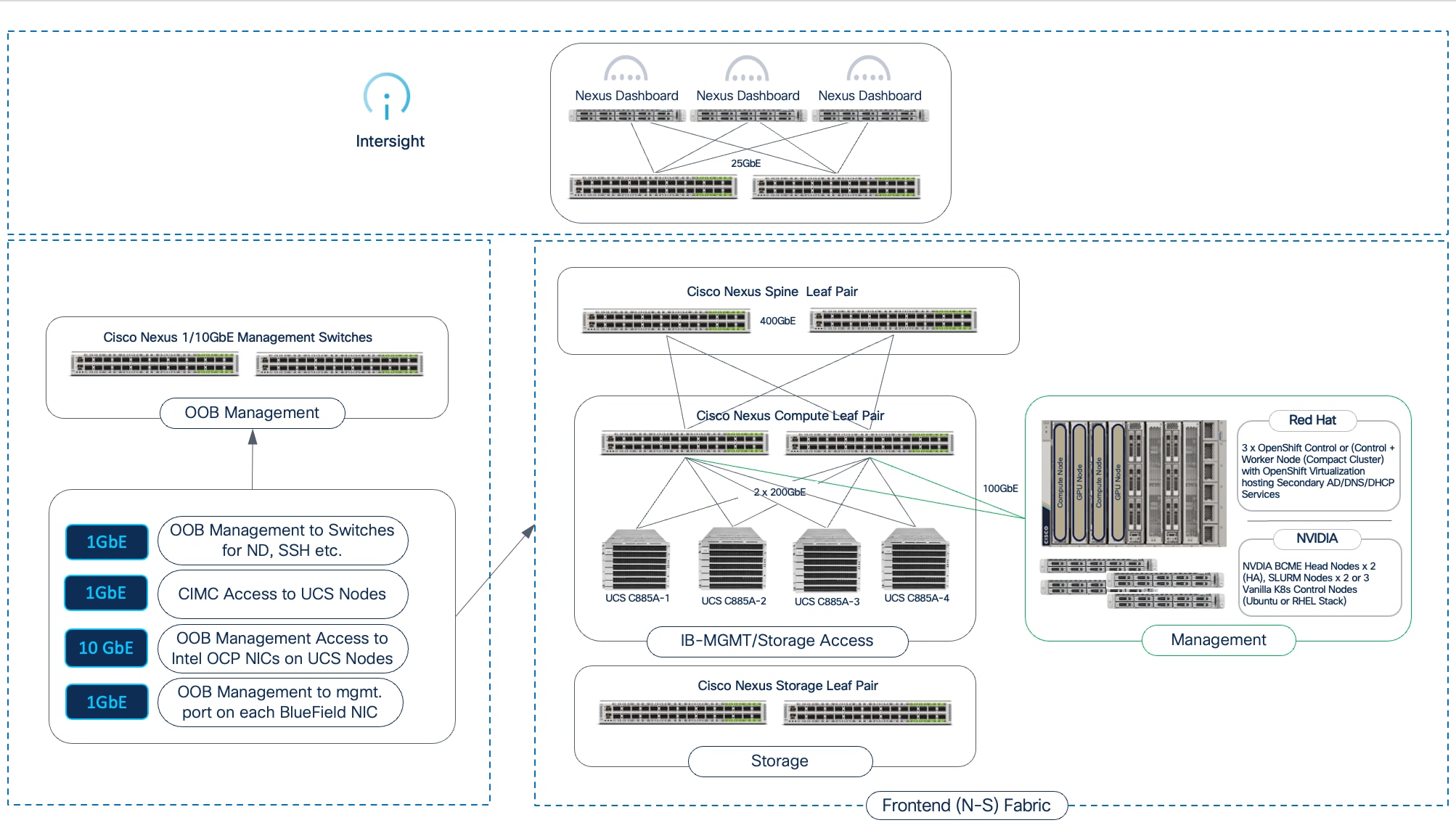
Resource Management
In OpenShift AI , resource management is centralized and policy-driven, allowing administrators to optimize hardware utilization, enforce quotas, and ensure fair sharing in multi-tenant environments. This is achieved through integration with OpenShift's core scheduling and monitoring capabilities, with enhancements for AI-specific demands like accelerators and distributed jobs.
Administrators configure resources via the OpenShift AI dashboard or cluster APIs, starting with hardware provisioning for data science projects. This includes defining accelerator types, such as NVIDIA GPUs or other specialized hardware, using node labels and tolerations to route workloads to appropriate nodes. For instance, GPU nodes can be labeled for selective access, preventing unauthorized use and optimizing for compute-intensive tasks.
Kueue plays a central role in job queuing and scheduling, managing resource contention by queuing workloads when clusters are oversubscribed. It supports priority-based queuing, fair sharing across teams, and integration with distributed frameworks like Ray. Administrators set up cluster queues to define resource pools (for example, a queue for GPU-heavy training with limits on concurrent jobs), ensuring efficient allocation without starvation. Best practices include monitoring queue metrics to adjust policies dynamically and using admission controls to validate resource requests.
User and project quotas enforce limits on CPU, memory, storage, and accelerators per data science project or group. This prevents resource hogging, with options to set hard limits (for example, maximum GPUs per project) and soft limits for bursting. Telemetry configuration collects usage data for capacity planning, integrating with OpenShift's Prometheus-based monitoring to alert on thresholds.
Model Training
Model training in OpenShift AI leverages Kubernetes-native capabilities for both single-node and distributed scenarios, abstracting infrastructure complexity while supporting large-scale workloads. Training jobs execute as standard pods or distributed clusters, with resource requests for accelerators and integration with Kueue for queuing in contended environments. Key tools include Kubeflow Trainer Operator, which enables distributed training and fine-tuning using frameworks like PyTorch with Fully Sharded Data Parallel (FSDP), reducing memory footprint and accelerating convergence for LLMs. Training Hub provides cookbooks and algorithms like Supervised Fine-Tuning (SFT) and Orthogonal Subspace Fine-Tuning (OSFT), allowing continual post-training to expand knowledge without catastrophic forgetting. Management starts from workbenches for prototyping or pipelines for automation, with jobs submitting via SDKs or UI. Features support dynamic hardware-aware strategies, VRAM estimation, and checkpointing for fault tolerance. Integration with Ray for scale-out and model registry for versioning trained artifacts.
Model Customization or Fine-Tuning: Red Hat OpenShift AI enables organizations to tailor artificial intelligence models to unique operational requirements by fine-tuning pre-existing models with proprietary datasets. This customization workflow is supported by integrated toolkits, including Docling for converting unstructured data into structured formats and the Synthetic Data Generation (SDG) Hub for augmenting datasets to improve model robustness. The Red Hat AI Training Hub simplifies the fine-tuning process through algorithms like Supervised Fine-Tuning (SFT) and Orthogonal Subspace Fine-Tuning (OSFT), while the Kubeflow Trainer Operator (KFTO) abstracts infrastructure complexity to allow for distributed training across multiple nodes. To ensure a secure software supply chain, the platform provides a maintained Red Hat Python index, offering reliable access to supported libraries even in disconnected environments.

Distributed Workloads
Distributed workloads leverage the Ray framework for horizontal scaling of compute-intensive tasks like data-parallel or model-parallel training, designed as operator-managed clusters that abstract infrastructure details. In , enhancements include PyTorch v2.8.0 training images with ROCm and CUDA compatibility for GPU acceleration, Kubeflow Trainer for Kubernetes-native distributed training and fine-tuning, and support for creating/managing Ray Jobs using CodeFlare SDK, aligning with KubernetesFlow Training Operator for automated job handling. Features encompass fault tolerance through checkpointing, auto-scaling based on load metrics, and integration with Kueue for queuing oversubscribed jobs. Management starts with enabling the Ray component in the operator configuration, then launching clusters from the dashboard or SDK, submitting jobs from workbenches or pipelines. Integration allows orchestrated workflows: Pipelines can trigger Ray jobs for large-scale processing, while monitoring captures metrics like job completion and resource utilization.
Data Science Pipelines
KFP-based pipelines author workflows visually or programmatically, with versioned runs and artifacts stored in S3-compatible storage. Enhancements include better tracking and integration with model registries and customization tools.
Security in Red Hat OpenShift AI
OpenShift AI inherits OpenShift's defense-in-depth model, with additions for AI-specific risks like LLM vulnerabilities. OpenShift AI strengthens security by providing a framework to ensure machine learning models are transparent, fair, and reliable. According to the sources, it utilizes the TrustyAI Guardrails Orchestrator to proactively filter harmful inputs and outputs in real-time while employing the TrustyAI service for continuous long-term monitoring. This dual-layered strategy protects against immediate adversarial exploits and identifies systemic risks such as bias or performance degradation.
Key Features of OpenShift AI Monitoring and Guardrails:
● TrustyAI Guardrails Orchestrator: A centralized tool that invokes detections on text generation inputs and outputs to secure LLM applications.
● Built-in PII Detectors: Out-of-the-box algorithms to identify and block Personally Identifiable Information, including social security numbers, credit card details, and email addresses.
● Content Moderation: Integration with Hugging Face models to filter hateful, profane, or toxic (HAP) language.
● Adversarial Protection: Specialized detectors designed to mitigate prompt injection attacks by blocking malicious prompts before they reach the model.
● Fairness Monitoring: Continuous tracking of model bias using metrics like Statistical Parity Difference (SPD) and Disparate Impact Ratio (DIR).
● Data Drift Detection: Statistical tests, such as Mean-Shift and Kolmogorov-Smirnov (KSTest), that identify when real-world data distributions deviate from training data.
● Guardrails Gateway: A mechanism for enforcing consistent safety policies through unique, preset pipeline endpoints.
Enterprise Observability: Support for OpenTelemetry to export traces and metrics, providing an audit trail for security and governance mechanisms.
This section details the management and operational model for managing the AI POD training infrastructure. Figure 31 shows the management components and infrastructure required to manage an AI POD training cluster.

Out-of-Band (OOB) Management Network
A dedicated Out-of-Band (OOB) management network is a fundamental requirement for the initial bring-up of this infrastructure, as well as for reliable access for troubleshooting and management. This physically separate OOB network connects the management ports of all infrastructure components such as Nexus switches, Cisco UCS servers (CIMC), and BlueField NICs to a dedicated pair of 1/10GbE management switches. This network also provides essential connectivity to network and other enterprise services to such as Active Directory (AD) for authentication, DHCP for IP address assignment, PXE boot, and DNS for name resolution to access management components within and outside the enterprise.
In-Band Management
In-band Management network is used for day-to-day operational tasks and for high-bandwidth telemetry once the environment is up and running. Traffic for in-band management traverses the frontend fabric with other data traffic.
In-band connectivity is necessary to support per-flow telemetry from Nexus Dashboard. This enables the collection of detailed, real-time information on network flows, such as latency and packet drops, for troubleshooting and performance monitoring. While switch management and other telemetry collection from Nexus Dashboard can be done over either the out-of-band or in-band network, these high-bandwidth telemetry streams are only possible in-band.
In the AI POD design, the in-band management network is used to connect the dedicated UCS management cluster with the UCS C8xx GPU nodes across the frontend fabric.
Dedicated Management and Services Cluster
To operationalize the AI POD infrastructure, a dedicated Management and Services Cluster is used to host the management and control plane components for the chosen software stack on the UCS GPU nodes. This cluster is separate from the GPU compute nodes and connects to the AI POD’s frontend fabric using its in-band management network as shown in Figure 31.
The management cluster is built using flexible Cisco UCS servers, such as the Cisco UCS C-Series Rack Servers or Cisco UCS X-Series Direct systems. These servers provide the necessary compute, memory, and local storage capacity for running the management and components of the software stack. The number of nodes required depends on the chosen software stack and its high-availability (HA) requirements (for example, a minimum of three nodes is typical for an HA Kubernetes control plane).
Software Stacks
The AI POD design supports two primary, enterprise-grade software stacks on the UCS GPU nodes in the cluster, each with its own management and control plane components that run on this dedicated management cluster:
● NVIDIA Stack with BCME: This stack is ideal for environments that prefer an all-in-one cluster management tool with an HPC-like operational model. The management cluster hosts the BCME Head Nodes (typically two for HA), which offer a comprehensive solution for provisioning, monitoring, and managing the entire GPU cluster. BCME can automate the bare-metal provisioning of the Ubuntu OS, manage software packages, provide detailed monitoring, and offer a unified administration dashboard. For workload management, either SLURM or Vanilla Kubernetes can be used, which would require an addition two for SLURM and three for Kubernetes
● Red Hat OpenShift: This stack is designed for enterprises standardizing on Kubernetes for AI/ML and other applications. The management cluster hosts the OpenShift Control Plane Nodes, while the UCS GPU nodes are worker nodes in the same cluster. OpenShift uses an Operator-based framework to simplify the management of complex software. For the AI POD, the NVIDIA GPU Operator and Network Operator are critical for automating the deployment and lifecycle management of the necessary NVIDIA drivers and enabling features like GPUDirect RDMA on the GPU worker nodes. The OpenShift cluster can also be deployed as a compact cluster (combined control and worker nodes), and if enabled for OpenShift Virtualization, it can also host redundant services such as AD, DHCP, DNS and so on. The control plane can also be a Hosted Control Plane to scale and support multiple clusters if needed.
For smaller deployments, the management cluster can connect to the same compute leaf switches used by the GPU nodes. However, for higher scale and greater separation of functions, a dedicated pair of management/services leaf switches can be used to connect to the management cluster. This approach also provides a clear path for expanding and adding future services to the cluster.
Compute Infrastructure Management with Cisco Intersight
The Cisco Intersight platform provides a unified SaaS-based management of all Cisco UCS infrastructure in the AI POD. Intersight enables a high level of automation, simplicity, and operational efficiency for server lifecycle management.
Note: While Intersight provides comprehensive management for the UCS platform, support for specific new hardware like the Cisco UCS C8xx series evolves over time. Always consult the latest Intersight documentation for the current level of support and available features for these servers.
As you scale by adding more Scale Units, Nexus Dashboard and Intersight ensure deployment ease and operational consistency across the entire expanded infrastructure.
Network Fabric Management with Cisco Nexus Dashboard
Cisco Nexus Dashboard
The backend and frontend fabrics in the AI POD are centrally managed using Cisco Nexus Dashboard, providing unified fabric management and visibility. Nexus Dashboard takes a software-defined approach, enabling centralized, fabric-level deployments instead of switch-by-switch configuration, which minimizes errors and maintains consistency. This "one fabric" approach simplifies overall management and provides a single API endpoint for automation. This consistent design, managed by Nexus Dashboard, allows the AI POD to scale smoothly from a small cluster to a large, multi-cluster environment.
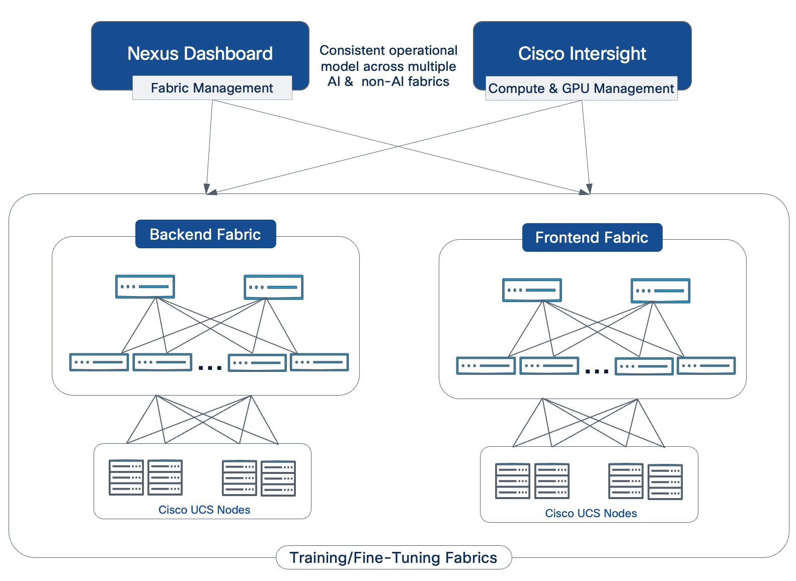
Nexus Dashboard offers configuration templates to simplify deployment and provides telemetry and flow-level analytics. These configuration templates capture Cisco's recommended best practices through default options but also allow modifications to support a customized deployment. For AI/ML environments, best-practices-based AI/ML templates are available specifically for both the backend and frontend fabric, enabling it to be provisioned in minutes.
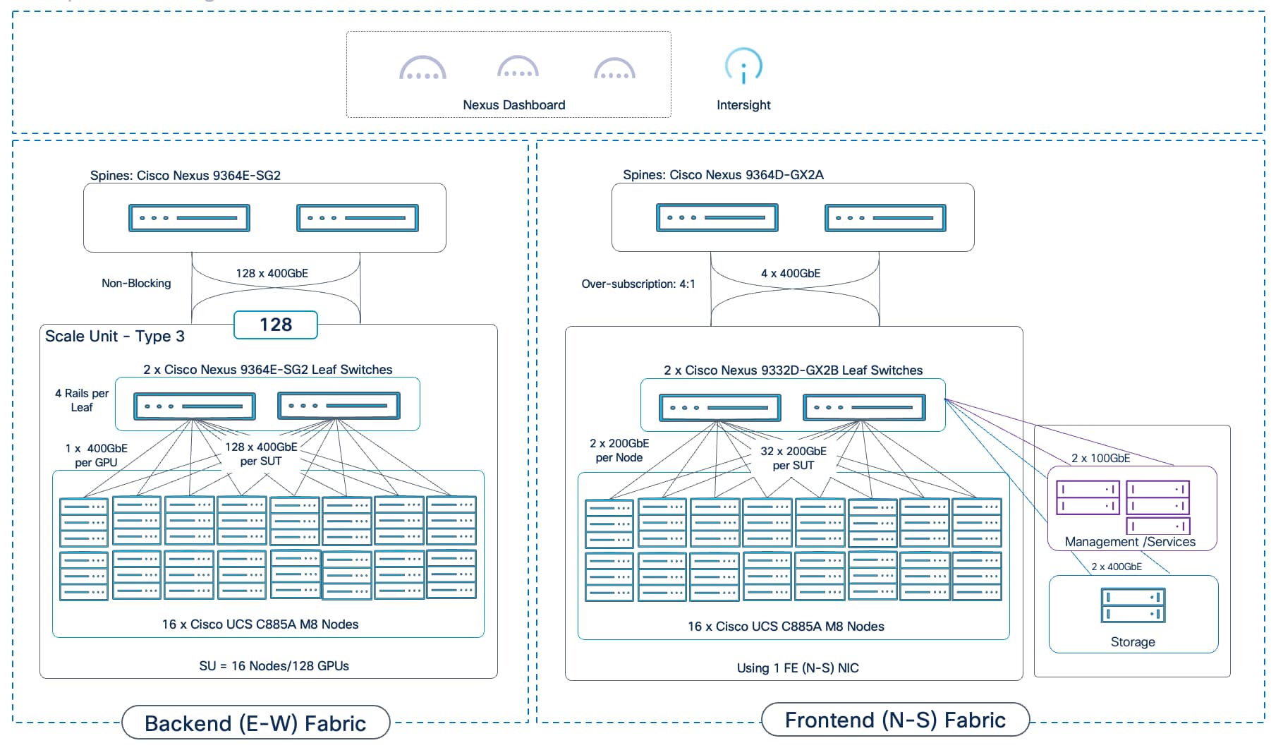
A comprehensive observability strategy is essential for operating an AI training infrastructure. It provides the necessary visibility to troubleshoot issues, optimize performance, manage resources, and ensure the health of the entire AI POD. The design leverages a dual approach: using domain-specific tools for deep vertical insights and the Splunk Observability Cloud as the unified platform that correlates data across the entire stack.
Domain-Specific Monitoring
● GPU Monitoring: When running Kubernetes, the NVIDIA Data Center GPU Manager (DCGM) Exporter is automatically deployed on each UCS GPU server when the NVIDIA GPU Operator is deployed. This enables the collection of critical metrics such as GPU utilization, memory usage, and temperature, which can also be viewed directly from within domain-specific tools like the Red Hat OpenShift cluster console. This data can also be sent to Splunk Observability cloud for comprehensive monitoring of the entire environment. This data is essential for understanding workload performance at the most granular level.
● Infrastructure Monitoring: AI POD leverages Cisco Intersight and Red Hat OpenShift (when using this stack) to provide monitoring of the infrastructure environment. Cisco Intersight provides deep visibility into the health, status, and alarms for the Cisco UCS servers, including power, temperature, and fan speed metrics.
● Network Fabric Monitoring: Cisco Nexus Dashboard collects telemetry data and provides deep visibility into the health and performance of both the frontend and backend network fabrics, allowing operators to monitor link utilization, latency, and any potential network-level issues.
While these tools are powerful for domain-specific analysis, their true value is realized when their data is streamed to a central platform for correlation.
Comprehensive Observability with Cisco Splunk
The AI POD design leverages the Splunk Observability Cloud to provide a unified platform that correlates metrics, traces, and logs from every layer of the stack. Instead of hopping from one domain manager to the next, Splunk offers a single pane of glass view the entire stack that accelerates troubleshooting by providing deep insights into the health and performance of the entire AI infrastructure.
Key advantages of Cisco Spunk are:
● OpenTelemetry-Native: Splunk's native support for OpenTelemetry avoids vendor lock-in and allows instrumentation to be done once on a common, open standard.
● AI-Powered Analytics: AI/ML-driven features like Service Maps and Trace Analytics provide directed guidance that helps operators resolve issues faster.
● No Data Sampling: Splunk’s NoSample tracing ensures that 100% of data is collected and analyzed, eliminating blind spots that can occur with sampled data.
The foundation for this is comprehensive data collection via the Splunk OpenTelemetry Collector, which streamlines the data collection from all sources:
● Infrastructure and GPU Metrics: The collector is configured to scrape metrics from Cisco UCS servers (CPU, memory), Nexus switches (network statistics), and, critically, from the NVIDIA DCGM (Data Center GPU Manager) Exporter. This brings essential GPU metrics such as utilization, memory usage, temperature, and power draw, directly into Splunk.
● Kubernetes and AI Workload Logs: The collector gathers logs, traces and metrics from all containerized AI workloads and applications running on the Kubernetes cluster. It can also monitor key NVIDIA AI Enterprise components, including the NVIDIA NIM operator and microservices for LLM inferencing.
The power of Splunk is the unified dashboards, which provide a holistic view of the AI POD's health. An operator can see correlated data in one place, enabling capabilities such as:
● Cluster-wide GPU Utilization: An overview of how effectively the expensive GPU resources are being used across all tenants.
● Unified Cluster View: Monitor all Kubernetes clusters (including Red Hat OpenShift) and individual Cisco UCS servers from a single interface.
● Per-Tenant Resource Consumption: Dashboards filtered by Kubernetes namespace to show a specific tenant's usage against their assigned Resource Quotas (GPU, CPU, memory).
● Node-Level Health: A detailed view of individual UCS servers, correlating a spike in GPU temperature (from DCGM) with high CPU load and storage network traffic on the same node.
● Network Fabric Performance: Key metrics from the Nexus switches for both the frontend and backend fabrics, showing link utilization and any potential congestion.
● AI POD Infrastructure Health: Track critical metrics like GPU utilization, GPU memory usage, power, and network performance by integrating data directly from Cisco Intersight and Cisco Nexus switches.
● Real-Time Troubleshooting: Leverage Splunk’s AI-powered analytics and NoSample™ full-fidelity tracing to diagnose issues in minutes. For example, if an LLM application experiences high latency, an operator can instantly trace the issue to an underutilized GPU and reconfigure the workload to use all available resources, restoring performance immediately.
Figure 34 shows a custom Splunk dashboard built for the AI POD validation in Cisco labs.
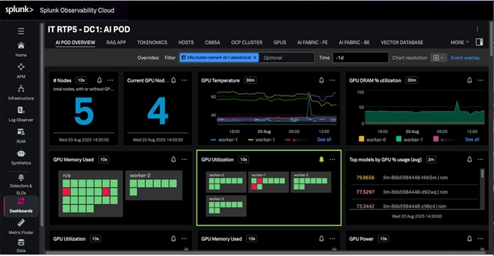
Bringing it all together – AI POD Solution
This chapter contains the following:
● Scaled AI POD Training Design Examples
● Ordering
This chapter builds on the architectural building blocks and subsystem design discussed in the previous sections to present complete AI POD solutions for various for various scale points. Each design includes the required components, connectivity details, and a Bill of Materials (BOM) to guide planning and procurement. These prescriptive design options are then followed by the specific topology that was validated for this CVD.
Scaling AI POD Training Design Examples
As discussed, the AI POD architecture uses a modular building-block approach based on Scale Units. To provide standardized and repeatable deployment patterns, this design defines three specific blueprints known as Scale Unit Types. Each type is designed to maximize the port density of a specific Nexus leaf switch pair used in the backend fabric, resulting in building blocks of 32, 64, and 128 GPUs when using the Cisco UCS C885A server. Enterprises can start with one of these pre-defined Scale Unit Types and then add more units over time to reach higher scale targets (for example, 256, 512 GPUs).
The following sections present three design options built using Scale Unit - Type 3. This 128-GPU building block represents a relatively large starter cluster for many enterprises and provides a pathway for scaling to 512 GPUs without introducing a super-spine tier. A similar methodology can be applied to building clusters with the smaller 32- or 64-GPU Scale Unit Types.
AI POD Design: 128 GPU Cluster
Figure 35 shows a complete AI POD infrastructure design for a 128-GPU training and fine-tuning cluster, built using a single Scale Unit – Type 3 as the foundational building block.

The design uses dedicated GPU backend and frontend fabrics. The frontend fabric provides connectivity for storage, management, and other services. It can be extended to support hybrid deployments with inferencing workloads in the future. The design can support either:
● Cisco UCS C885A M8 servers (8 GPUs per node): This server supports 8 East-West NICs for the backend fabric and 1 or 2 North-South NICs for the frontend fabric.
● Cisco UCS C845A M8 servers (up to 8 GPUs per node): This server supports a maximum of 4 East-West NICs (one for every two GPUs) and one North-South NIC, resulting in less connectivity and cabling requirements compared to a UCS C885A deployment.
AI POD Design: 256 GPU Cluster
Figure 36 shows a complete AI POD infrastructure design for a 256-GPU training and fine-tuning cluster, built using a single Scale Unit – Type 3 as the foundational building block.
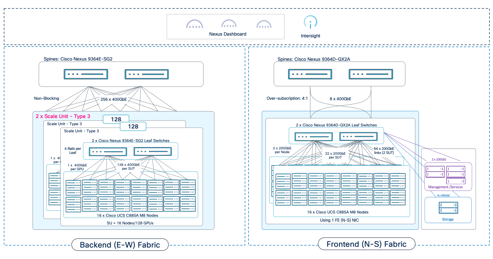
AI POD Design: 512 GPU Cluster
Figure 37 shows a complete AI POD infrastructure design for a 512-GPU training and fine-tuning cluster, built using a single Scale Unit – Type 3 as the foundational building block.
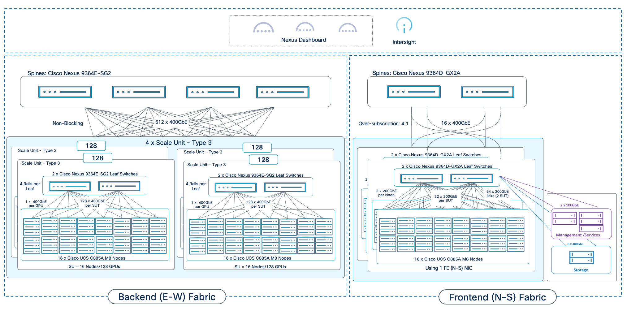
The modular design of the AI POD allows enterprises to start with a right-sized infrastructure and scale as their AI initiatives grow. However, this flexibility requires careful physical planning. The high density of GPU servers means that power, cooling, and rack space are critical design considerations that must be planned for from the beginning.
Planning should account for the eventual scale of the cluster, as there are certain scale points where the design change can have a significant impact on the physical layout and cabling. In the AI POD architecture, scaling beyond 512 GPUs is one such inflection point.
This chapter provides a sample rack layout for a 256 GPU cluster to illustrate the physical planning required. This example is based on a specific set of assumptions regarding the power and connectivity requirements. The assumptions are:
● Target Cluster Size: 256 GPU cluster, built using 2 x 128 GPU Scale Unit – Type 3 clusters
● Server: Cisco UCS C885A M8 Server with 8x H200 GPUs and 8 BE (1 x 400GbE) NICs and 1 FE (2 x 200GbE) NIC
● Rack Specification: 42 RU racks with 30kW of power to each rack
● Backend Fabric Design: 2-way Rail-Optimized (4 rails per switch)
The table below provides the detailed power requirements and calculations for the components used in this example:
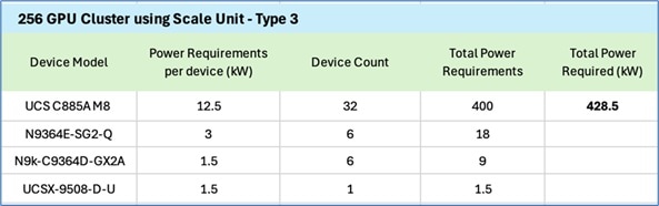
Note: Cisco UCS X-Series chassis in the above table is the management Cisco UCS with 3 servers (control plane).
The figure below shows a sample rack layout for the 256 GPU cluster in this example:
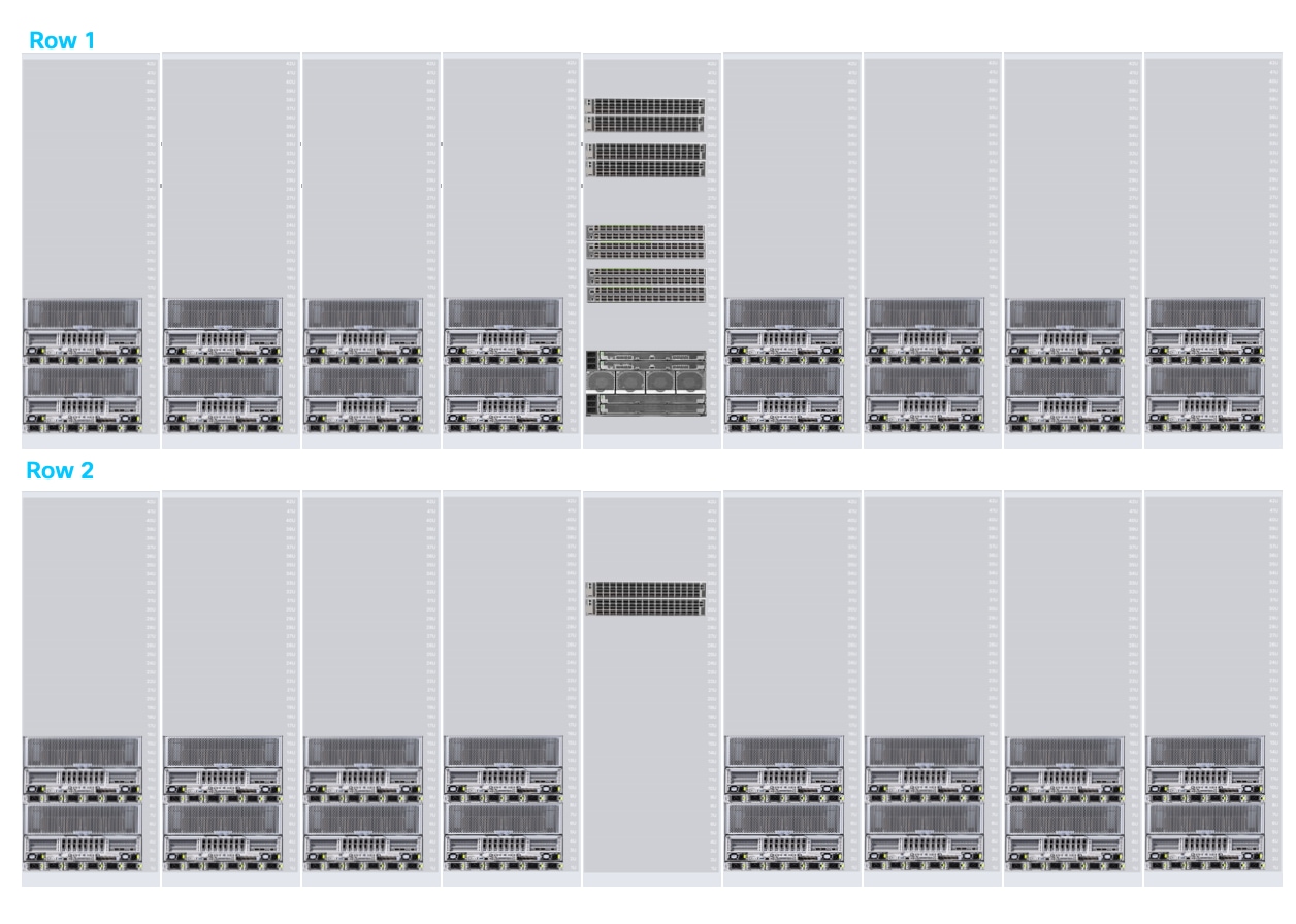
A few things to note about this layout:
● The first row shows the first Scale Unit – Type 3 with 16 Cisco UCS C885A servers with the leaf pair it connects to, in both the backend and front-end fabric.
● The second row shows the second Scale Unit – Type 3. This will require the front-end connections to go from Row 2 to Row 1. From a cabling perspective, it would be easier to use a smaller port-density pair of front-end leaves in both Row 1 and Row 2 so that there is a pair of frontend leaves for each row (similar to backend leaf pair)
● Row 1’s middle rack includes both frontend and backend spine switches and Management UCS server, unlike Row 2, in addition to the backend (for Scale Unit -Type 3) and frontend leaf switches for both rows, unless the 2 x Nexus 9364D-GX2A frontend leaf switches are replaced with 4 x Nexus 9332D-GX2B, a pair per row.
● Out-of-Band 1/10GbE ethernet switch is not show in the rack layout but it could also be deployed in the middle rack. This can also be split across rows by adding a smaller port-density switch pair to each row.
● Each server-only rack consumes ~12.5KW x 2 = 25KW of the 30KW rack.
● Row 1 (Switch + Management) as shown in above figure consumes: 4 x 3kW (per N9364E-SG2) + 4 x 1.5kW (per 9364D-GX2A) + ~1.5KW (Cisco UCS-X with 3 Cisco UCS M8 control nodes) = ~20kW. This allows for ~10kW of space for storage if there is sufficient RU in this rack. Total rack space used by the gear in this rack is 23 RU (25 RU if OOB mgmt. switch is deployed in this rack or if space is left between the gear for cabling). In a 42RU rack, this leaves ~17RU of space for storage and associated gear.
Bill of Materials
A sample BOM for the 256 GPU cluster is provided in Figure 38. The requirements for other cluster sizes can be derived from this. The Cisco UCS server in the configuration below uses one N-S NIC to connect to frontend fabric.
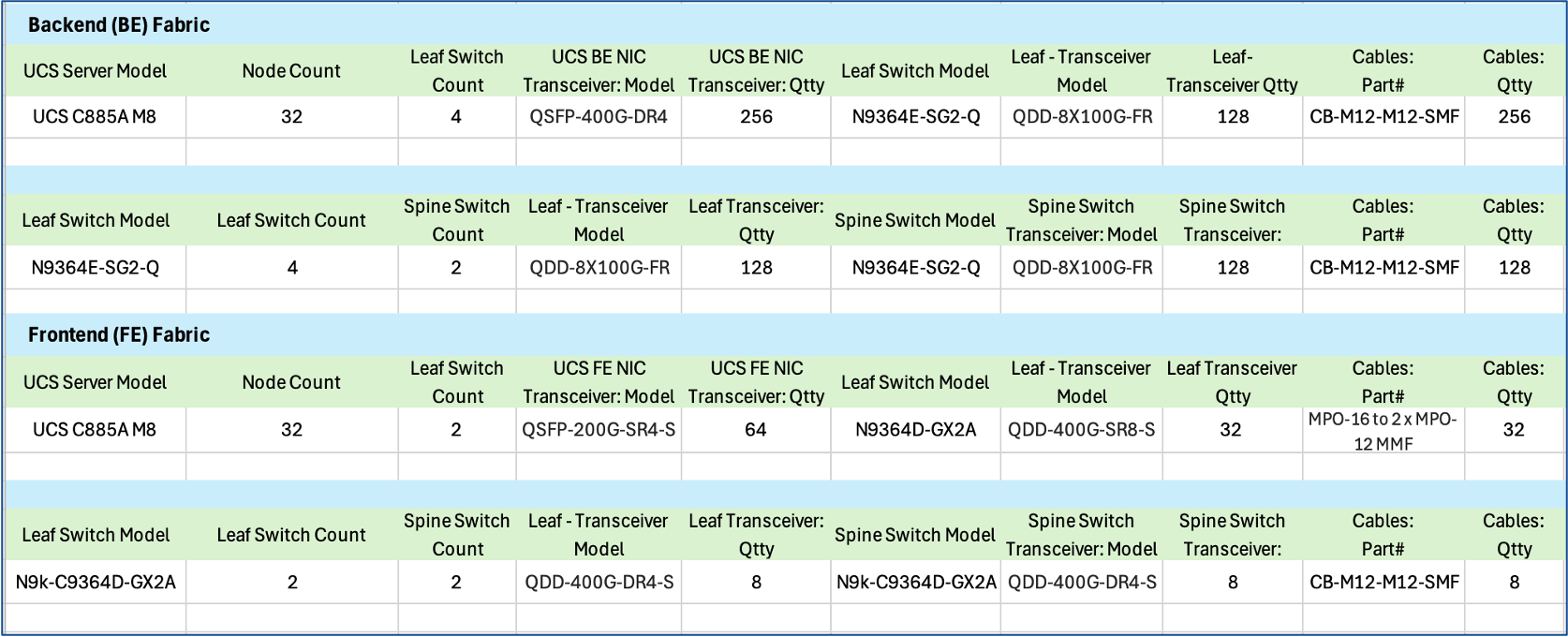
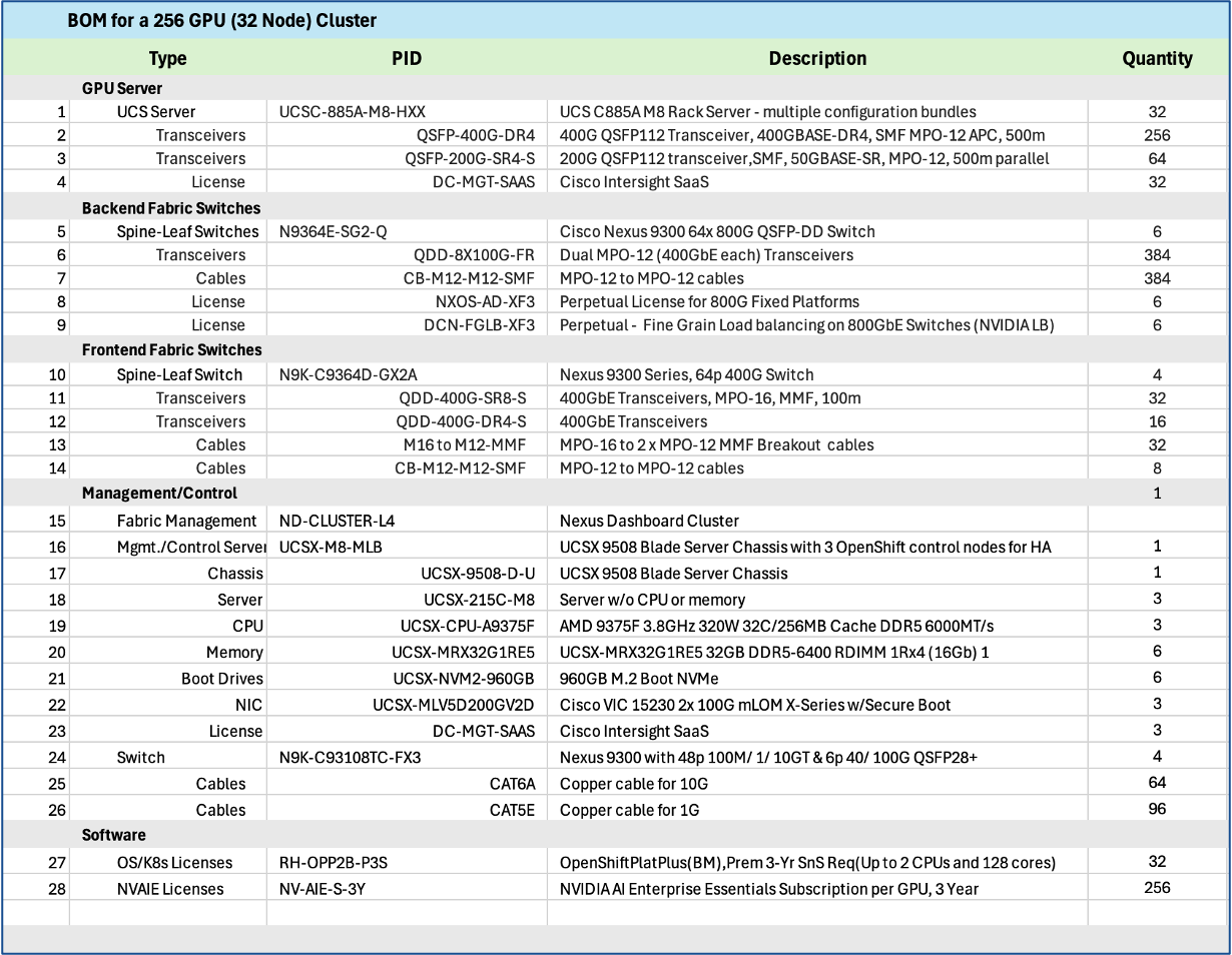
Solution GitHub Repo
The solution repository provides configurations, validation use case code, and other useful tips and information. Repo is accessible here: https://github.com/ucs-compute-solutions/Cisco-AI-POD.
Licensing
Additional information on licensing for the different components in the AI POD stack are available here:
● Cisco Intersight Licensing: https://intersight.com/help/saas/getting_started/licensing_requirements/lic_intro
● Cisco Nexus NX-OS Licensing Options Guide: https://www.cisco.com/c/en/us/td/docs/switches/datacenter/licensing-options/cisco-nexus-licensing-options-guide.html
● NVIDIA Licensing: https://www.cisco.com/c/en/us/td/docs/unified_computing/ucs/release/notes/nvidia_ordering-guide.html
● Red Hat OpenShift Licensing: https://www.redhat.com/en/resources/self-managed-openshift-subscription-guide
Transceivers
To find the supported transceivers for any component in the AI POD stack, including interoperability between them, see the following links. Cisco’s TMG Matrix is the place regardless of the product.
● Main site and relevant sub-sites for Cisco’s Transceiver Matrix Group:
● Transceivers Data Sheets
◦ Cisco QSFP-DD800 Transceiver Modules Data Sheet: https://www.cisco.com/c/en/us/products/collateral/interfaces-modules/transceiver-modules/qsfp-dd800-transceiver-modules-ds.html
◦ Cisco OSFP 800G Transceiver Modules Data Sheet: https://www.cisco.com/c/en/us/products/collateral/interfaces-modules/transceiver-modules/osfp-800g-transceiver-modules-ds.html
◦ Cisco 200G QSFP56 Cables and Transceiver Modules Data Sheet: https://www.cisco.com/c/en/us/products/collateral/interfaces-modules/transceiver-modules/nb-06-200g-qsfp56-cables-trans-mod-ds-cte-en.html
This section details the specific solution that was built and validated in Cisco labs for this CVD.
Validated Design Topology
The validated design topology is illustrated in Figure 39.
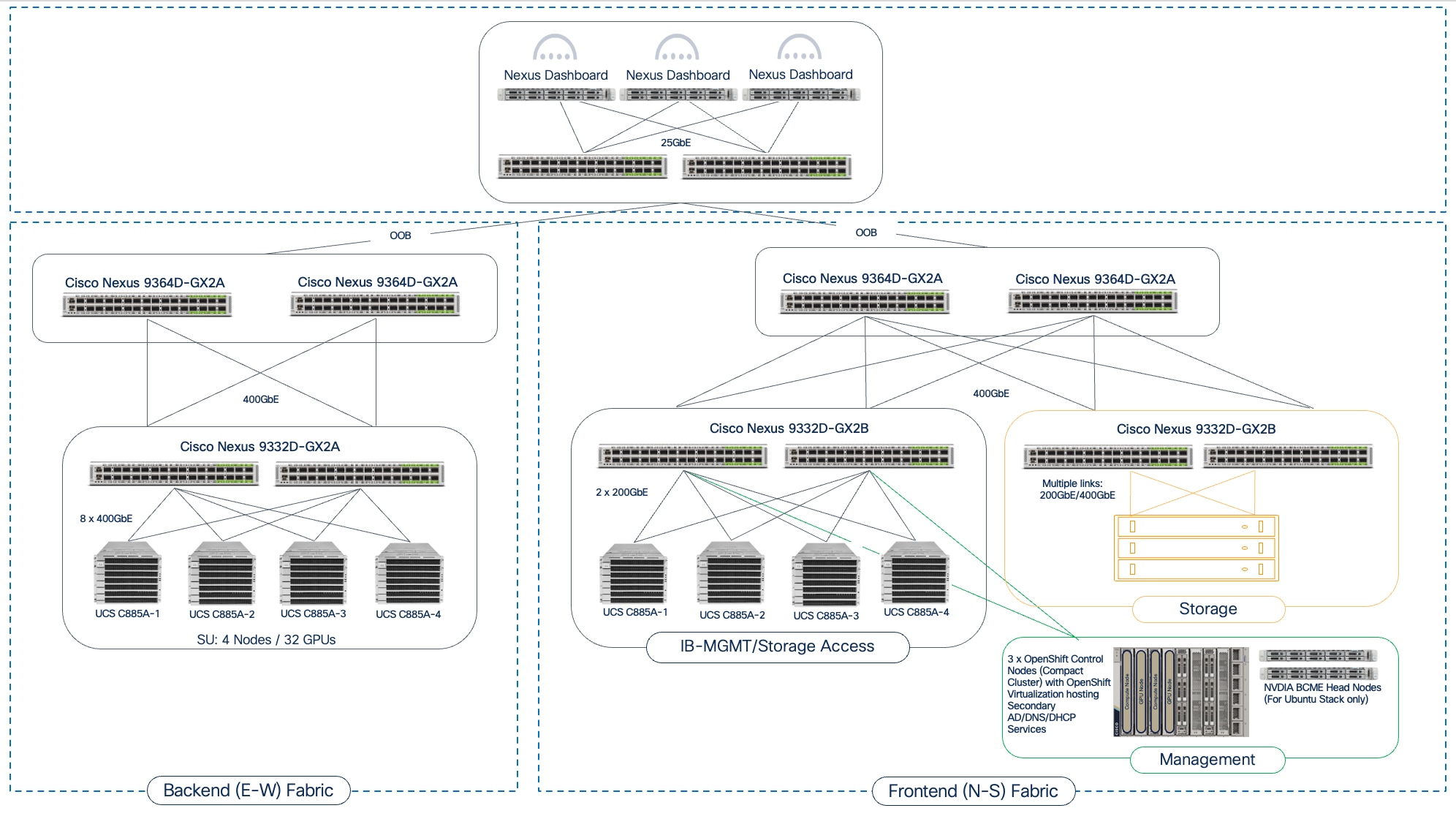
Hardware and Software Components Matrix
Table 12 lists the hardware and software components for the Ubuntu and Red Hat OpenShift based stacks.
Note: These versions may get updated during validation. Please see the deployment guides (when released) for the final versions used.
Table 12. Hardware and Software Matrix
| Component (PID) |
Software/Firmware |
Notes |
| Backend Fabric |
||
| Cisco Nexus 9332D-GX2B |
NXOS 10.4(3) or higher |
Spine and Leaf switches |
| Frontend Fabric |
||
| Cisco Nexus 9364D-GX2A |
NXOS 10.4(3) or higher |
Spine and Leaf switches |
| UCS Compute |
||
| Cisco UCS C885A |
|
|
| NVIDIA H200 GPU Driver |
570.133.20 |
Minimum version |
| CUDA Version |
12.8 |
Minimum version |
| Management / Services |
||
| Cisco Nexus Dashboard |
4.1(1) |
3-node physical cluster |
| Cisco Intersight |
N/A |
SaaS platform |
| Cisco UCS X-Series |
|
|
| Cisco UCS X9508 Chassis (UCSX-9508) |
N/A |
|
| Cisco UCS X Direct 100G (UCSX-S9108-100G) |
4.3(5.240162) |
|
| Cisco UCS X210c M7 Compute Nodes (UCSX-210C-M7) |
5.2(2.240080) |
Minimum of 3 nodes as control nodes for OpenShift or NVIDIA BCME |
| PCIe Mezzanine Card for UCS-X server (UCSX-V4-PCIME) |
N/A |
Optional: Only necessary for GPUs on UCS-X |
| Cisco UCS X440p PCIe Node |
N/A |
Optional: Only necessary for GPUs on Cisco UCS-X |
| Cisco VIC 15231 MLOM (UCSX-ML-V5D200G) |
5.3(3.91) |
2x100G mLOM |
| Operating System/Workload Orchestration |
||
| Red Hat OpenShift |
4.16 or higher |
Deployed using Assisted Installer from console.redhat.com |
| Red Hat NFD Operator |
Default version |
Node Feature Discovery Operator (NFD) to identify and label GPU |
| NVIDIA GPU Operator |
25.3.4 or higher |
|
| NVIDIA Network Operator |
25.7.0 |
For up-to-date drivers and to enable GPUDirect RDMA for GPU-to-GPU on BE and GPU-to-Storage on FE |
| NVIDIA Base Command Manager |
10.0 |
|
| SLURM |
Default version |
Workload Manager |
| Ubuntu |
22.04.4 LTS |
|
Interoperability Matrices
The interoperability information for the different components in the solution are summarized in Table 13.
| Component |
Interoperability Matrix and Other Relevant Links |
| Cisco UCS Hardware Compatibility Matrix (HCL) |
|
| NVIDIA Licensing |
|
| NVIDIA Certification |
https://www.nvidia.com/en-us/data-center/products/certified-systems/ |
| NVIDIA AI Enterprise Qualification and Certification |
|
| NVIDIA Driver Lifecycle, Release and CUDA Support |
https://docs.nvidia.com/datacenter/tesla/drivers/index.html#lifecycle |
Cisco and NVIDIA have a strong partnership to accelerate AI adoption by simplifying how organizations deploy, manage, and secure AI infrastructure. This collaboration spans multiple layers, from fundamental platform compatibility and server certifications to comprehensive, full-stack reference architectures. This multi-faceted partnership is designed to de-risk AI infrastructure deployments for our customers so that they can harness the full potential of AI to deliver tangible business outcomes for their organizations.
Cisco has both NVIDIA “Certified” platforms and Enterprise Reference Architecture “Compliant” designs, as detailed below.
NVIDIA Certified Platforms
Cisco offers a range of NVIDIA “Certified” UCS servers designed for AI, high-performance computing (HPC), and accelerated workloads. These systems have been tested and validated for optimal performance.
Key NVIDIA-Certified Cisco UCS platforms include:
● UCS C845A with L40S, H200 NVL, and RTX Pro 6000 GPUs
● UCS C885A with H100 and H200 GPUs
For a complete list of NVIDIA Certified Servers, see: https://marketplace.nvidia.com/en-us/enterprise/qualified-system-catalog/?limit=15
Enterprise Reference Architecture Compliant Designs
Beyond certifying individual Cisco UCS servers, Cisco collaborates with NVIDIA on Enterprise Reference Architectures (RA). The Enterprise Reference Architecture includes a range of designs, starting from a 32 GPU cluster using a two switch, 2-way rail-optimized network design to 1k GPU cluster using a 3-tier, 8-way rail-optimized spine-leaf design.
For more information about Cisco’s Enterprise RA Compliant designs, see:
Updated Enterprise RA Compliance Criteria
NVIDIA’s criteria for Enterprise RA “Compliant’ design requires (at the time of writing of this document) the following for a design to be endorsed by NVIDIA through the Enterprise RA program:
● Switching that supports Spectrum-X enablement for the East-West networking.
● Spectrum-X enablement to be activated and licensed for the East-West networking.
● Adhere to the relevant Spectrum-X RA design patterns such as 4 leaf (2 rail/switch) HGX design.
● Cisco Nexus 9000 Series Cloud-Scale and Silicon One switches meet the above criteria. For more information, see the Nexus Licensing Guide and Cisco AI Networking for Data Center with NVIDIA Spectrum-X Solution Overview paper provided in Appendix A - References.
NVIDIA’s Enterprise Reference Architecture Documents
For more information on NVIDIA’s Enterprise RA designs, refer to the following document. Links are not available and requires access to NVIDIA’s Partner Portal so providing the title and version of the documents here:
● ERA-00003-001_v04 - NVIDIA HGX H100+H200+B200 8-GPU and NVIDIA Spectrum Platforms - 28th February 2025
● ERA-00010-001_v01 - Network Deployment Guide NVIDIA SpectrumX Platforms - 4th July 2025
The Cisco AI POD architecture will continue to evolve and is designed to be extensible. For instance, the dedicated Management and Services Cluster can be expanded to include additional value-added services in the future and eventually a Services Pod for a scaled deployment. One such critical service is Cisco AI Defense.
Cisco AI Defense
As models are fine-tuned, it becomes essential to analyze them for security vulnerabilities, data poisoning, or adversarial evasion techniques. Extending the management cluster to support a services cluster provides the ideal, isolated environment to run these security analysis tools post-fine-tuning before the models are considered for production use. In a hybrid deployment with inferencing, AI Defense can provide run-time protection, for which a service cluster with proximity to the GPU cluster (model) is necessary to secure the inferencing pipeline while providing low-latency (real-time), inferencing response that it require.
Cisco C880A M8 Server with B300 GPUs
A key future extension to AI POD will be the integration of Cisco’s newest dense-GPU AI server, Cisco UCS C880A M8 Server. This next-generation platform combines the power of NVIDIA’s Blackwell-based HGX B300 GPUs with the high-core-count performance of Intel Xeon 6 processors to deliver significant performance leap compared to previous generations of NVIDIA GPUs, for both training and real-time LLM inference.
These and other advanced services will be explored in future design guides. For more details on AI Defense and use cases where it can be leveraged, see Appendix A - References.
Conclusion
Cisco AI POD is a comprehensive infrastructure solution for enterprises, designed to support their AI/ML journey and a range of AI workloads from training to fine-tuning to inferencing. The AI POD solution detailed in this document is a complete, integrated, and full-stack infrastructure specifically tailored for AI training and fine-tuning workloads. This architecture directly addresses unique AI requirements of enterprises, such as support for multiple smaller workloads with multi-tenancy, incremental scale with operational simplicity and consistency, and ease of integration into existing data center environments.
The Cisco AI POD solution for AI training and fine-tuning includes GPU-dense compute (UCS AI platforms), high-performance networking (Cisco Nexus), storage from industry-leading partners, and a robust AI software stack running on Linux or Kubernetes. Each AI POD is built, integrated, and validated in Cisco labs, backed by Cisco Validated Designs, and provides solution-level support through Cisco TAC. While focused on core infrastructure today, Cisco AI POD solutions are designed to evolve, supporting advanced security solutions (Cisco AI Defense, Hypershield) and new technology trends, thereby providing a future-ready platform.
The architectural approach of AI PODs ensures infrastructure is right-sized and can grow with enterprise adoption. This avoids upfront investments in large, potentially underutilized clusters—an important consideration given the rapid pace of technology innovation in the AI space. By leveraging the modularity and flexibility of Scale Units (for example, 32, 64, or 128 GPU clusters), combined with operational ease, design simplicity, and incremental scalability, Cisco AI PODs ensure consistency across all deployment vectors, even at scale.
By adopting Cisco AI PODs, enterprise organizations have a complete, pre-validated solution to meet their full spectrum of AI infra requirements and accelerate AI adoption in a secure manner. This approach reduces time-to-value, lowers total cost of ownership, and empowers enterprises to confidently operationalize AI initiatives that bring value to the business.
About the author
Archana Sharma, Principal Technical Marketing Engineer, Cisco UCS Solutions, Cisco Systems Inc.
Archana Sharma is a Principal Technical Marketing Engineer with over 20 years of experience developing solutions across a wide range of technologies, including Data Center, Desktop Virtualization, Collaboration, and other Layer 2 and Layer 3 technologies. In her current role, Archana’s focusses on the design, developing and validating Cisco UCS based AI solutions for enterprise data centers. She is the author of several Cisco Validated Designs, and a regular speaker at industry events like Cisco Live. Archana holds a CCIE (#3080) in routing and switching and a bachelor’s degree in electrical engineering from North Carolina State University.
Acknowledgements
For their support and contribution to the design, validation, and creation of this Cisco Validated Design, the author would like to thank:
● Ramesh Isaac, Technical Marketing Engineer, Cisco Systems, Inc.
● John George, Technical Marketing Engineer, Cisco Systems, Inc.
● Anil Dhiman Technical Marketing Engineer, Cisco Systems, Inc
● Marina Ferreira, Principal Solutions Engineer, Cisco Systems, Inc.
● Chris O’Brien, Senior Director, Technical Marketing, Cisco Systems, Inc
Cisco IT Team
● Louis Watta, Director, Software Engineering
● Weiguo Sun, Principal Engineer
● Chris Baldwin, Technical Systems Architect
● Mohammed A Jameel, Network Systems Engineering Technical Leader
● Nikhil Mitra, SRE Technical Leader
● Kevin Marschalk, Program Manager
● Gurudatt Katakdhond, Technical Program Manager
Appendix
This appendix contains the following:
Appendix A - References
AI POD Solutions
● Design Zone for AI Ready Infrastructure: https://www.cisco.com/c/en/us/solutions/design-zone/ai-ready-infrastructure.html
● GitHub Repo for Cisco UCS Solutions: https://github.com/ucs-compute-solutions
Backend Fabric
General
● Evolve your AI/ML Network with Cisco Silicon One: https://www.cisco.com/c/en/us/solutions/collateral/silicon-one/evolve-ai-ml-network-silicon-one.html
● Doubling all2all Performance with NVIDIA Collective Communication Library 2.12: https://developer.nvidia.com/blog/doubling-all2all-performance-with-nvidia-collective-communication-library-2-12/
● Cisco Massively Scalable Data Center Network Fabric Design and Operation White Paper: https://www.cisco.com/c/en/us/products/collateral/switches/nexus-9000-series-switches/white-paper-c11-743245.html
QoS References
● Network Best Practices for Artificial Intelligence Data Center: https://www.ciscolive.com/c/dam/r/ciscolive/emea/docs/2025/pdf/BRKDCN-2921.pdf
● Cisco Data Center Networking Blueprint for AI/ML Applications: https://www.cisco.com/c/en/us/td/docs/dcn/whitepapers/cisco-data-center-networking-blueprint-for-ai-ml-applications.html
● RoCE Storage Implementation over NX-OS VXLAN Fabrics: https://www.cisco.com/c/en/us/td/docs/dcn/whitepapers/roce-storage-implementation-over-nxos-vxlan-fabrics.html
Load Balancing References
● Nexus Improves Load Balancing and Brings UEC Closer to Adoption (Blog): https://blogs.cisco.com/datacenter/nexus-improves-load-balancing-and-brings-uec-closer-to-adoption
● Cisco AI Networking for Data Center with NVIDIA Spectrum-X Solution Overview: https://www.cisco.com/c/en/us/products/collateral/networking/cloud-networking-switches/nexus-9000-switches/ai-networking-dc-nvidia-spectrum-x-so.html
● Meet Cisco Intelligent Packet Flow: https://www.cisco.com/c/en/us/products/collateral/ios-nx-os-software/nx-os-software/intelligent-packet-flow-solution-overview.html
● Cisco Nexus 9000 Series NX-OS Unicast Routing Configuration Guide, Release 10.5(x): https://www.cisco.com/c/en/us/td/docs/dcn/nx-os/nexus9000/105x/unicast-routing-configuration/cisco-nexus-9000-series-nx-os-unicast-routing-configuration-guide/m-configure-dynamic-load-balancing.html
● AI-Ready Infrastructure: A New Era of Data Center Design: https://blogs.cisco.com/datacenter/ai-ready-infrastructure-a-new-era-of-data-center-design
● Why Cisco Nexus 9000 with Nexus Dashboard for AI Networking White Paper: https://www.cisco.com/c/en/us/products/collateral/networking/cloud-networking-switches/nexus-9000-switches/nexus-9000-ai-networking-wp.html
● Cisco Nexus 9000 Series Switches for AI Clusters White Paper with Performance Validation Insights: https://www.cisco.com/c/en/us/products/collateral/switches/nexus-9000-series-switches/nexus-9000-series-switches-ai-clusters-wp.html
NVIDIA
● (PXN) Doubling all2all Performance with NVIDIA Collective Communication Library 2.12: https://developer.nvidia.com/blog/doubling-all2all-performance-with-nvidia-collective-communication-library-2-12/
● NVIDIA Collective Communications Library (NCCL): https://developer.nvidia.com/nccl
● NIVIDIA Enterprise Reference Architecture (NVIDIA does not provide links that can be shared. However, the exact titles are provided below. Cisco has access to these using NVIDIA’s Partner Portal:
◦ ERA-00003-001_v04 - NVIDIA HGX H100+H200+B200 8-GPU and NVIDIA Spectrum Platforms - 28th February 2025
◦ ERA-00010-001_v01 - Network Deployment Guide NVIDIA SpectrumX Platforms - 4th July 2025 (2)
● GPUDirect: https://developer.nvidia.com/gpudirect
Splunk
● Unlocking AI Performance: Splunk Observability for Cisco Secure AI Factory with NVIDIA: https://blogs.cisco.com/datacenter/unlocking-ai-performance-splunk-observability-for-cisco-secure-ai-factory-with-nvidia
Security
● Cisco AI Defense: https://www.cisco.com/site/us/en/products/security/ai-defense/index.html
● AI Defense on Cisco AI PODs Reference Architecture: https://www.cisco.com/c/en/us/td/docs/unified_computing/ucs/UCS_CVDs/AI_defense_on_Cisco_AI_PODs_reference_architecture.html
Cisco UCS AI Servers
● Cisco UCS Hardware Compatibility List (HCL) Tool: https://ucshcltool.cloudapps.cisco.com/public/
● Cisco’s Transceiver Matrix Group:
Cisco UCS C885A M8 Server
● Cisco UCS C845A M8 Server: https://www.cisco.com/c/dam/en/us/products/collateral/servers-unified-computing/ucs-c-series-rack-servers/ucs-c845a-m8-rack-server-spec-sheet.pdf
● Cisco UCS C885A M8 Data Sheet: https://www.cisco.com/c/en/us/products/collateral/servers-unified-computing/ucs-c-series-rack-servers/ucs-c885a-m8-ds.html
● Cisco UCS C885A M8 Spec Sheet: https://www.cisco.com/c/dam/en/us/products/collateral/servers-unified-computing/ucs-c-series-rack-servers/ucs-c885a-m8-rack-server-spec-sheet.pdf
● Cisco UCS C885A M8 Server Installation and Service Guide: https://www.cisco.com/c/en/us/support/servers-unified-computing/ucs-c-series-rack-servers/products-installation-guides-list.html
● Cisco UCS C885A M8 At-a-Glance: https://www.cisco.com/c/en/us/products/collateral/servers-unified-computing/ucs-c-series-rack-servers/ucs-c885a-m8-aag.html
Cisco UCS C845A M8 Server
● Cisco UCS C845A M8 Rack Server Data Sheet: https://www.cisco.com/c/en/us/products/collateral/servers-unified-computing/ucs-c-series-rack-servers/ucs-c845a-m8-rack-server-ds.html
● Cisco UCS C845A M8 AI Server Spec Sheet: https://www.cisco.com/c/dam/en/us/products/collateral/servers-unified-computing/ucs-c-series-rack-servers/ucs-c845a-m8-rack-server-spec-sheet.pdf
● Cisco UCS C845A M8 AI Servers Memory Guide: https://www.cisco.com/c/dam/en/us/products/collateral/servers-unified-computing/ucs-c-series-rack-servers/ucs-c845Am8-memory-guide.pdf
● Cisco UCS C845A M8 Rack Server At a Glance: https://www.cisco.com/c/en/us/products/collateral/servers-unified-computing/ucs-c-series-rack-servers/ucs-c845a-m8-rack-server-aag.html
Cisco UCS C880A M8 Server
● Cisco UCS C880A M8 Rack Server Data Sheet: https://www.cisco.com/c/en/us/products/collateral/servers-unified-computing/ucs-c-series-rack-servers/ucs-c880a-m8-rack-server-ds.html
● Cisco UCS C880A M8 Rack Server Spec Sheet: https://www.cisco.com/c/dam/en/us/products/collateral/servers-unified-computing/ucs-c-series-rack-servers/ucs-c880a-m8-rack-server-spec-sheet.pdf
Cisco Nexus Switches
● Cisco Nexus 9332D-GX2B and Nexus 9364D-GX2A Switch Data Sheet: https://www.cisco.com/site/us/en/products/collateral/networking/switches/nexus-9000-series-switches/nexus-9300-gx2-series-fixed-switches-data-sheet.html#tabs-35d568e0ff-item-4bd7dc8124-tab
● Cisco Nexus 9364E-SG2 Switch Data Sheet: https://www.cisco.com/c/en/us/products/collateral/switches/nexus-9000-series-switches/nexus-9364e-sg2-switch-ds.html
● Cisco Nexus Dashboard 4.1: Data Center Management for the AI Era - Cisco Blogs: https://blogs.cisco.com/datacenter/announcing-the-new-nexus-dashboard-for-simplifying-data-center-operations-in-the-ai-era
● Cisco Nexus Dashboard 4.1.1 Release notes: https://www.cisco.com/c/en/us/td/docs/dcn/nd/4x/release-notes/cisco-nexus-dashboard-release-notes-411.html
● Cisco Nexus Dashboard Data Sheet: https://www.cisco.com/c/en/us/products/collateral/data-center-analytics/nexus-dashboard/datasheet-c78-744371.html
● Cisco Data Center Networking (DCN) Licensing Ordering Guide: https://www.cisco.com/c/en/us/products/collateral/data-center-analytics/nexus-dashboard/guide-c07-744361.html
● (Internal) Cisco Nexus Dashboard 4.1 release updates - Seller Guide: https://salesconnect.seismic.com/Link/Content/DCb3d1cbc5-fb94-4583-86fe-c64261203275
● (Internal) EMEA Cloud & AI Infrastructure PVT May 2025 - Exploring the Nexus Dashboard 4.x releases – PDF: https://salesconnect.seismic.com/Link/Content/DC7cce6697-d173-4ddf-892c-3d6813a17816
VAST Data
● VAST Data: https://www.vastdata.com/whitepaper
Pure Storage
● Pure Storage: https://www.purestorage.com/
● Pure Storage FlashBlade: https://www.purestorage.com/products/unstructured-data-storage.html
● Portworx by Pure Storage: https://www.purestorage.com/products/cloud-native-applications/portworx.html
Feedback
For comments and suggestions about this guide and related guides, join the discussion on Cisco Community here: https://cs.co/en-cvds.
CVD Program
"DESIGNS") IN THIS MANUAL ARE PRESENTED "AS IS," WITH ALL FAULTS. CISCO AND ITS SUPPLIERS DISCLAIM ALL WARRANTIES, INCLUDING, WITHOUT LIMITATION, THE WARRANTY OF MERCHANTABILITY, FITNESS FOR A PARTICULAR PURPOSE AND NONINFRINGEMENT OR ARISING FROM A COURSE OF DEALING, USAGE, OR TRADE PRACTICE. IN NO EVENT SHALL CISCO OR ITS SUPPLIERS BE LIABLE FOR ANY INDIRECT, SPECIAL, CONSEQUENTIAL, OR INCIDENTAL DAMAGES, INCLUDING, WITHOUT LIMITATION, LOST PROFITS OR LOSS OR DAMAGE TO DATA ARISING OUT OF THE USE OR INABILITY TO USE THE DESIGNS, EVEN IF CISCO OR ITS SUPPLIERS HAVE BEEN ADVISED OF THE POSSIBILITY OF SUCH DAMAGES.
THE DESIGNS ARE SUBJECT TO CHANGE WITHOUT NOTICE. USERS ARE SOLELY RESPONSIBLE FOR THEIR APPLICATION OF THE DESIGNS. THE DESIGNS DO NOT CONSTITUTE THE TECHNICAL OR OTHER PROFESSIONAL ADVICE OF CISCO, ITS SUPPLIERS OR PARTNERS. USERS SHOULD CONSULT THEIR OWN TECHNICAL ADVISORS BEFORE IMPLEMENTING THE DESIGNS. RESULTS MAY VARY DEPENDING ON FACTORS NOT TESTED BY CISCO.
CCDE, CCENT, Cisco Eos, Cisco Lumin, Cisco Nexus, Cisco StadiumVision, Cisco TelePresence, Cisco WebEx, the Cisco logo, DCE, and Welcome to the Human Network are trademarks; Changing the Way We Work, Live, Play, and Learn and Cisco Store are service marks; and Access Registrar, Aironet, AsyncOS, Bringing the Meeting To You, Catalyst, CCDA, CCDP, CCIE, CCIP, CCNA, CCNP, CCSP, CCVP, Cisco, the Cisco Certified Internetwork Expert logo, Cisco IOS, Cisco Press, Cisco Systems, Cisco Systems Capital, the Cisco Systems logo, Cisco Unified Computing System (Cisco UCS), Cisco UCS B-Series Blade Servers, Cisco UCS C-Series Rack Servers, Cisco UCS S-Series Storage Servers, Cisco UCS X-Series, Cisco UCS Manager, Cisco UCS Management Software, Cisco Unified Fabric, Cisco Application Centric Infrastructure, Cisco Nexus 9000 Series, Cisco Nexus 7000 Series. Cisco Prime Data Center Network Manager, Cisco NX-OS Software, Cisco MDS Series, Cisco Unity, Collaboration Without Limitation, EtherFast, EtherSwitch, Event Center, Fast Step, Follow Me Browsing, FormShare, GigaDrive, HomeLink, Internet Quotient, IOS, iPhone, iQuick Study, LightStream, Linksys, MediaTone, MeetingPlace, MeetingPlace Chime Sound, MGX, Networkers, Networking Academy, Network Registrar, PCNow, PIX, PowerPanels, ProConnect, ScriptShare, SenderBase, SMARTnet, Spectrum Expert, StackWise, The Fastest Way to Increase Your Internet Quotient, TransPath, WebEx, and the WebEx logo are registered trade-marks of Cisco Systems, Inc. and/or its affiliates in the United States and certain other countries. (LDW_P6)
All other trademarks mentioned in this document or website are the property of their respective owners. The use of the word partner does not imply a partnership relationship between Cisco and any other company. (0809R)