Cisco Nexus 9000 Series Switches for AI Clusters White Paper Performance validation insights
Available Languages
Bias-Free Language
The documentation set for this product strives to use bias-free language. For the purposes of this documentation set, bias-free is defined as language that does not imply discrimination based on age, disability, gender, racial identity, ethnic identity, sexual orientation, socioeconomic status, and intersectionality. Exceptions may be present in the documentation due to language that is hardcoded in the user interfaces of the product software, language used based on RFP documentation, or language that is used by a referenced third-party product. Learn more about how Cisco is using Inclusive Language.
Performance validation insights
Cisco has built multiple AI clusters for use cases such as model training, fine tuning, and inferencing in its own data centers. The value Cisco derives from these AI clusters is reflected in its following products and use cases:
● Cisco® Webex® for improved audio (noise cancellation and bandwidth prediction) and video (background replacement and gesture recognition).
● Cisco security offerings for AI-driven service analysis and predictions.
● Order-collection optimizations, payment predictions, and fraud analysis.
● Observability to bring accuracy in IT infrastructure changes, to avoid business-impacting incidents.
As of early 2025, Cisco’s AI clusters are powered by NVIDIA H100 and H200 DGX systems. Ethernet networks, built using Cisco Nexus® 9000 Series switches, connect the GPUs in different DGX nodes. Cisco Nexus Dashboard is the platform of choice for network configuration, monitoring, and operations.
This document summarizes network design and validation of Cisco’s on-premises AI clusters. Based on this validation, your organization can deploy Cisco Nexus 9000 Series switches confidently for building Ethernet-based AI networks, thereby eliminating risk, accelerating time to production, and increasing return on investments in AI clusters.
“AI workloads, including model training and retraining, require extensive data processing, making the network a vital part of AI infrastructure. It connects high-performance computing systems and GPUs, necessitating high performance and reliability to handle the substantial bandwidth demands. Cisco Nexus 9000 Series switches and Nexus Dashboard have been utilized to efficiently manage these capabilities, ensuring optimal performance.
The Nexus 9000 switches offer a high-performance and low-latency Ethernet fabric optimized for inter-GPU networks, essential for AI workloads. Establishing this infrastructure in an on-premises data center provides the necessary advantages to meet requirements. Nexus Dashboard facilitates the build, deploy, and management of AI network infrastructure, offering observability insights to support teams.”
Ram Ramkumar
Director, Technical Systems Engineering,
Cisco IT NEO – Data Center Network Services
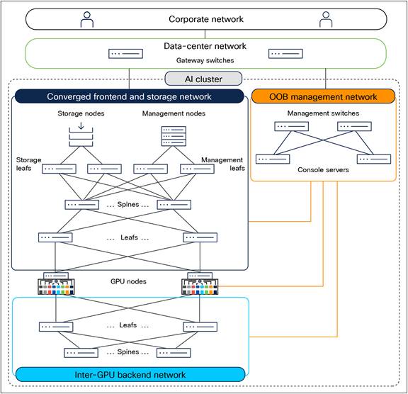
An AI cluster typically has multiple networks—an inter-GPU backend network, a frontend network, a storage network, and an Out-Of-Band (OOB) management network.
Figure 1 shows an overview of these networks. Users (in the corporate network in the figure) and applications (in the data-center network) reach the GPU nodes through the frontend network. The GPU nodes access the storage nodes through a storage network, which, in Figure 1, has been converged with the frontend network. A separate OOB management network provides access to the management and console ports on switches, BMC ports on the servers, and Power Distribution Units (PDUs). A dedicated inter-GPU backend network connects the GPUs in different nodes for transporting Remote Direct Memory Access (RDMA) traffic while running a distributed job.
Network design for Cisco’s on-premises AI clusters.
Inter-GPU backend network design
Each GPU node has eight 400 Gigabit Ethernet (GE) ports for inter-GPU connectivity. For interconnecting these ports in different nodes, Cisco has built Ethernet-based, 400 Gigabits per second (Gbps) networks using 64-port 400 GE Nexus 9364D-GX2A switches (see Figure 2). This network is dedicated to GPU-to-GPU communication allowing UDP/IP packets for RDMA over Converged Ethernet version 2 (RoCEv2).
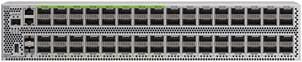
Cisco Nexus 9364D-GX2A switch with 64 400 GE QSFP-DD ports.
Cisco used the following principles for inter-GPU backend networks:
● Lossless network: Priority-based Flow Control (PFC) has been enabled for RoCEv2 traffic to prevent packet drops due to network congestion.
● Scalable unit of 256 GPUs: Cisco designed the backend network for 256 GPUs in a Scalable Unit (SU). To create a larger cluster, multiple scalable units can be interconnected between leaf and spine switches.
● Rail-optimized network design: GPUs in a scalable unit are interconnected using rail-optimized design to improve collective communication performance by allowing single-hop forwarding through the leaf switches, without the traffic going to the spine switches. In rail-optimized design, port 1 on all the GPU nodes connects to the first leaf switch, port 2 on all the GPU nodes connects to the second leaf switch, and so on.
● Nonblocking network design: The network is designed to be non-blocking for GPUs to send and receive traffic at full capacity simultaneously. This means that leaf switches have an equal number of downlinks to GPU nodes and uplinks to the spine switches.
Based on these design principles, Figure 3 shows Cisco’s 256 NVIDIA H100-based GPU cluster using eight leaf switches and four spine switches in the backend network.
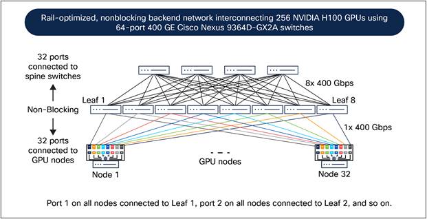
Inter-GPU backend network design for Cisco’s 256 NVIDIA H100 GPU cluster.
Extending the same principles to two scalable units, each with 256 GPUs, Figure 4 shows Cisco’s 512 NVIDIA H200-based GPU cluster. Each scalable unit uses eight leaf switches. Thus, two scalable units have 16 leaf switches, which are interconnected using eight spine switches in a nonblocking design. This 512 GPU backend network therefore uses 24 Nexus 9364D-GX2A switches.

Inter-GPU backend network design for Cisco’s 512 NVIDIA H200 GPU cluster all links operate at 400 Gbps.
The backend networks use Nexus 9364D-GX2A switches as leaf and spine. They connect with each other and to the GPU nodes using QDD-400G-DR4-S transceivers and MPO-12 cables (see Figure 5).
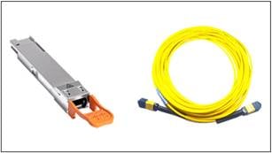
QDD-400G-DR4-S transceiver and MPO-12 cable.
Converged frontend and storage network design
Each NVIDIA DGX has two ports for connecting to the storage network and two ports for connecting to the frontend network. Initially, Cisco deployed separate networks for storage and frontend traffic. However, after a detailed analysis of the traffic pattern, the two networks were converged, as shown in Figure 1.
The converged frontend and storage network uses Cisco Nexus 93600CD-GX switches as leafs (see Figure 6) and Nexus 9364D-GX2A switches as spines (see Figure 2).
Nexus 93600CD-GX switches, as leafs, connect to the GPU nodes, storage nodes, and management nodes at 100 Gbps through the 28 100 GE ports using QSFP-100G-DR-S transceivers and SMF LC cables. These leaf switches connect to the spine switches through the eight 400 GE ports using QDD-400G-DR4-S transceivers and MPO-12 cables.
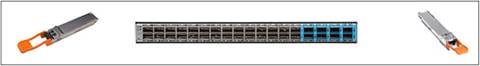
Cisco Nexus 93600CD-GX switch with 28 100 GE QSFP28 ports using QSFP-100G-DR-S transceivers (left) and eight 400 GE QSFP-DD ports using QDD-400G-DR4-S transceivers (right).
Nexus 9364D-GX2A switches, as spines, connect to the leaf switches through 64 400 GE ports using QDD-400G-DR4-S transceivers and MPO-12 cables.
The OOB management network connects the management ports of servers, switches, and PDUs using the 48 10GBASE-T ports on a Cisco Nexus 93108TC-FX3 switch (see Figure 7).
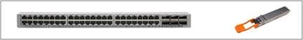
Cisco Nexus 93108TC-FX3 switch with 48 10GBASE-T and six 100 GE QSFP28 ports.
Cisco Catalyst® 8300 (C8300-1N1S-4T2X) is used for console connectivity to switches, servers, and storage nodes.
Network operations using Cisco Nexus Dashboard
Cisco uses Cisco Nexus Dashboard (ND) for operating the backend, frontend (converged storage), and OOB management networks of the AI clusters. These networks are configured as per the Cisco Data Center Networking Blueprint for AI/ML Applications.
Nexus Dashboard provides built-in templates based on the Cisco blueprint best practices to simplify the initial configuration of the networks. For proper handling of the RoCEv2 traffic in the inter-GPU backend network and for storage connectivity, Nexus Dashboard allows enabling PFC consistently on all switches using a single checkbox and offers Quality-of-Service (QoS) templates with optimized buffer thresholds. Figure 8 shows Nexus Dashboard topology view of a rail-optimized backend network of the 256 GPU cluster.
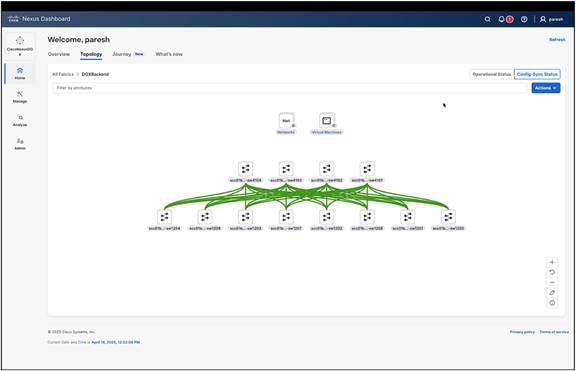
Nexus Dashboard topology view of the 256-GPU rail-optimized backend network.
The backend network configuration was automated using the built-in AI/ML routed fabric type in Nexus Dashboard. This fabric type uses Exterior Border Gateway Protocol (eBGP) for providing IP reachability between eight backend NIC ports on all the GPU nodes of a cluster. In the 512-GPU cluster, Cisco used VXLAN EVPN fabric type in the backend network.
Cisco uses Nexus Dashboard to automatically detect and generate anomalies for faster resolution of issues. As Figure 9 shows, Nexus Dashboard simplifies the interpretation of various congestion symptoms such as the number of pause frames sent or received, the number of Explicit Congestion Notification (ECN) marked packets, and traffic sent and received on a link by calculating per-interface and per-queue congestion scores and categorizing them as mild, moderate, or severe.
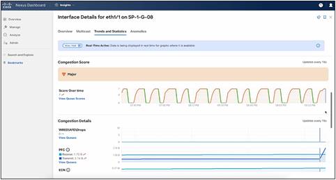
Nexus Dashboard showing congestion score with automatic red, orange, and green categorization.
Cisco deployed Nexus Dashboard on the management nodes (see Figure 1) with in-band connectivity to the frontend network and out-of-band connectivity to the backend network.
Inter-GPU backend network validation
This section summarizes the validation results of Cisco’s AI clusters interconnected using Cisco Nexus 9364D-GX2A switches.
Cisco used the RDMA/InfiniBand (IB) performance test tool to validate the RoCEv2 performance for inter-GPU communication. These tests validate that the lossless networking and routing are configured correctly and that end-to-end paths are healthy and can run line-rate traffic at 100% utilization.
Figure 10 shows 391 Gbps as the average bandwidth of the ib_write_bw test through a 400 Gbps interface on Cisco Nexus 9364D-GX2A switch. This is the maximum possible IB write bandwidth on a 400 Gbps link operating at 100% utilization after accounting for the RoCEv2 packet header overhead.
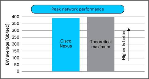
Line-rate RoCEv2 performance of Cisco Nexus 9364D-GX2A switches.
Figure 11 shows the results of RDMA bandwidth tests at various message sizes among GPUs in different nodes connected to the same leaf switches (within a rail when traffic benefits from single-hop forwarding by the leaf switch) and different leaf switches (crossing a rail boundary when traffic flows through the spine switches). In both cases, the 100-percent utilization of the 400 Gbps links was validated when the RDMA message size exceeded 64 KB.
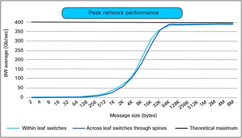
Line-rate RoCEv2 performance within rail and cross-rail using Cisco Nexus 9364D-GX2A switches.
Figure 12 shows the results of RDMA bandwidth tests across hundreds of random iterations among GPUs in different nodes connected to the same leaf switches (within a rail) and across different leaf switches (crossing a rail boundary). These validations show that Cisco Nexus 9000 Series switches deliver consistent RoCEv2 performance on all the links simultaneously. Such consistency is critical for the optimum performance of the inter-GPU communication because even one degraded RDMA operation can impact the performance of an entire job that is distributed on many GPUs.
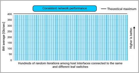
Consistent RoCEv2 performance of Cisco Nexus 9364D-GX2A.
Collective communication performance
Cisco used the NVIDIA Collective Communication Library (NCCL) tests to validate the performance of the inter-GPU backend network. These tests include AllReduce, AlltoAll, AllGather, and ReduceScatter operations.
Figure 13 shows the bus bandwidth (busbw) in GigaBytes per second (GB/s) for different collective communications among 256 GPUs connected through Cisco Nexus 9364D-GX2A switches. Bus bandwidth is a measure of the optimal use of the network for the inter-GPU communication, and therefore its higher value is better. Refer to the NCCL test documentation for a detailed explanation of these metrics.
Figure 13 shows the performance of an eBGP routed backend network. The performance with a VXLAN-based backend network is nearly identical, with only a 0.5 percent deviation. For example, AllReduce bus bandwidth with an eBGP-routed network for 64 GPUs was 390 GB/s, whereas with a VXLAN network, the AllReduce busbw was 389 GB/s. This small performance difference can be attributed to 50 bytes overhead of the VXLAN packet header.
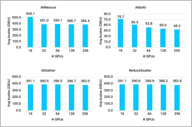
NCCL benchmarks from GPU nodes interconnected through an Ethernet network built using Cisco Nexus 9364D-GX2A switches.
Figure 14 shows the results of NCCL tests with 128 GPUs at various message sizes.
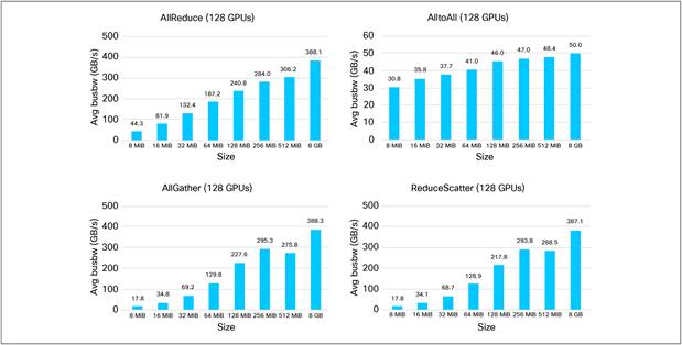
NCCL tests at various message sizes among 128 GPUs interconnected through an Ethernet network built using Cisco Nexus 9364D-GX2A switches.
These NCCL test results validated that the backend networks, built using Cisco Nexus 9364D-GX2A switches, deliver high performance and fair quality of service at various GPU scale and message sizes.
Cisco validated the full-stack performance of nodes, OS, GPUs, NIC, storage, and network by running distributed applications or training jobs such as MLPerf training benchmarks.
Figure 15 shows the results of LLama2-70B LoRA fine tuning MLPerf training benchmark v4.0 on 64 NVIDIA H100 GPUs in 8 nodes connected with Cisco Nexus 9364D-GX2A switches. It shows the Job-Completion Time (JCT) across ten iterations. After excluding the fastest and the slowest JCTs, the average JCT of the remaining iterations is 5.172 minutes. This result closely matches with or, in some cases, even exceeds other MLPerf training submissions with an InfiniBand-based backend network.
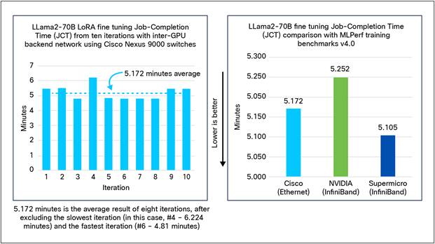
LLama2-70B LoRA fine tuning MLPerf training benchmark v4.0 performance with backend network of Cisco Nexus 9364D-GX2A switches.
Figure 16 shows the results of BERT MLPerf training benchmark v4.0 on 64 NVIDIA H100 GPUs in 8 nodes connected with Cisco Nexus 9364D-GX2A switches. It shows JCT across ten iterations. After excluding the fastest and the slowest values, the average JCT of the remaining iterations is 0.89 minutes. This result closely matches with or, in some cases, even exceeds the other MLPerf training submissions with an InfiniBand-based backend network.
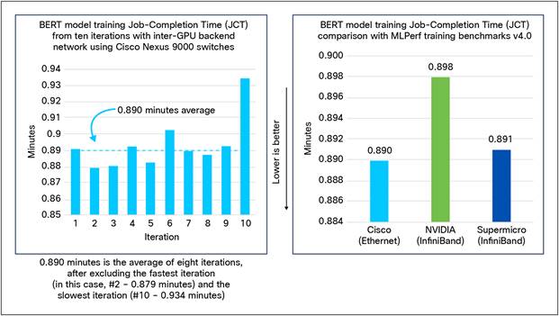
BERT MLPerf training benchmark v4.0 performance with backend network of Cisco Nexus 9364D-GX2A switches.
Figure 15 and 16 show that Cisco’s RoCEv2-based AI clusters match or exceed InfiniBand-based MLPerf training submissions. This validation is a significant testimonial of features and performance of Cisco Nexus 9000 switches.
Performance of load-balancing schemes
Non-uniform utilization of network links is one of the key challenges in inter-GPU backend networks. For details on these challenges and their solutions, please refer to the Cisco white paper on Cisco Data Center Networking Solutions: Addressing the Challenges of AI/ML Infrastructure.
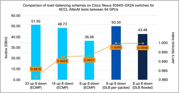
Figure 17 shows the results of the load-balance schemes available on Cisco Nexus 9000 switches. It illustrates the performance of the default Equal-Cost MultiPath (ECMP) load-balancing scheme based on 5-tuples of UDP/IP packets and Cisco Dynamic Load Balancing (DLB) feature in per-packet and flowlet mode.
The left-vertical axis shows the application performance, measured by bus bandwidth of NCCL all to all test under the following conditions:
● 32 up 8 down (ECMP): Default ECMP load-balancing scheme with 32 uplinks and 8 downlinks per leaf switch (under-subscription 4:1).
● 16 up 8 down (ECMP): Default ECMP load-balancing scheme with 16 uplinks and 8 downlinks per leaf switch (under-subscription 2:1).
● 8 up 8 down (ECMP): Default ECMP load-balancing scheme with 8 uplinks and 8 downlinks per leaf switch (non-blocking 1:1).
◦ These three tests illustrate performance impact of congestion due to link over-utilization caused by non-uniform link utilization while using ECMP load-balancing scheme.
● 8 up 8 down (DLB per-packet): DLB per-packet scheme with 8 uplinks and 8 downlinks per leaf switch (non-blocking 1:1).
◦ This feature delivered a performance gain of 37.5% (50.39 GB/s versus 36.66 GB/s) compared to the ECMP scheme, thereby demonstrating the efficient packet spraying capability of Cisco Nexus 9000 switches.
● 8 up 8 down (DLB flowlet): DLB flowlet scheme with 8 uplinks and 8 downlinks per leaf switch (Non-blocking 1:1).
◦ This feature delivered a performance gain of 18.6% (43.48 GB/s versus 36.66 GB/s) compared to the ECMP scheme, thereby demonstrating the efficient flowlet identification capability of Cisco Nexus 9000 switches.
Comparison of load-balancing schemes on Cisco Nexus 9000 switches for AI traffic
The right-vertical axis measures the uniform utilization of equal-cost links by the Jain’s fairness index. Figure 18 shows the formula for its calculation.
![]()
Jain’s fairness index to measure the uniform utilization of links
This index provides a mathematical approach to measure the success of network load-balancing schemes. It ranges between 0 and 1. Value of 1 means perfectly balanced links, whereas value of 0 means complete imbalance. Figure 17 shows that DLB per-packet scheme delivered a fairness score of 1.0, confirming perfect load balance among all the equal-cost links. DLB flowlet scheme is close, followed by the default ECMP scheme.
These validations prove that Cisco data center networking solutions are ready to address non-uniform utilization of network links, which is one of the key challenges in the inter-GPU backend network.
But Cisco’s AI clusters do not need these advanced load-balancing schemes today because the jobs can fit within the GPUs of a scalable unit (see Figure 3 and Figure 4), and therefore, most traffic benefits from the single-hop forwarding by the leaf switches. This also means that inter-GPU traffic does not go to the spine switches. As a result, the challenge of non-uniform link utilization is not observed today, and therefore the default ECMP approach is enough. Cisco still validated various load-balancing schemes to be ready for the future. AI technologies are evolving fast resulting in newer use cases. By validating advanced load-balancing features on Cisco Nexus 9000 switches, Cisco confirmed that its AI clusters are future-proof, their design is robust, and operational procedures are in place.
Cisco used the following components to build the AI clusters described in this document.
| PID |
Description |
Quantity for 256-GPU cluster |
Quantity for 512-GPU cluster |
| GPU nodes |
|||
| NVIDIA H100 or H200 |
NVIDIA H100 or H200 DGX systems running DGX OS 6.1.0 (Ubuntu 22.04.2 LTS), CUDA Version: 12.6 |
32 |
64 |
| Management nodes |
|||
| UCSC-C225-M8S |
Cisco UCS C225 M8 Rack Server |
8 |
8 |
| Storage nodes |
|||
| NetApp A90 or A900 |
NetApp AFF A90 or A900 nodes running ONTAP storage OS 9.15.1P4 |
4 |
4 |
| Backend network |
|||
| N9K-C9364D-GX2A |
Cisco Nexus 9364D-GX2A switch with 64 400 GE QSFP-DD ports running NX-OS 10.5(2) |
12 |
24 |
| QDD-400G-DR4-S |
400G QSFP-DD transceiver, 400GBASE-DR4, MPO-12 parallel SMF, 500m |
768 |
1536 |
| CB-M12-M12-SMF |
Cable, MPO12-MPO12, trunk cable, TYPE B, SMF, various lengths |
512 |
1024 |
| Converged frontend and storage network |
|||
| N9K-C9364D-GX2A |
Cisco Nexus 9364D-GX2A switch with 64 400 GE QSFP-DD ports running NX-OS 10.5(2) |
2 |
4 |
| N9K-C93600CD-GX |
Cisco Nexus 93600CD-GX switch with 28 100 GE QSFP28 and 8 400 GE QSFP-DD ports running NX-OS 10.5(2) |
8 |
10 |
| QDD-400G-DR4-S |
400G QSFP-DD transceiver, 400GBASE-DR4, MPO-12 parallel SMF, 500m |
128 |
256 |
| CB-M12-M12-SMF |
Cable, MPO12-MPO12, trunk cable, TYPE B, SMF, various lengths |
128 |
256 |
| QSFP-100G-DR-S |
100GBASE DR QSFP transceiver, 500m over SMF |
224 |
280 |
| CB-LC-LC-SMF |
Cable, duplex LC-LC patch cord, SMF, various lengths |
224 |
280 |
| OOB management network |
|||
| N9K-C93108TC-FX3 |
Cisco Nexus 93108TC-FX3 switch with 48 10GBASE-T and 6 100 GE QSFP28 ports running NX-OS 10.5(2) |
4 |
8 |
| QSFP-100G-DR-S |
100GBASE DR QSFP transceiver, 500m over SMF |
24 |
48 |
| CB-LC-LC-SMF |
Cable, duplex LC-LC patch cord, SMF, various lengths |
24 |
48 |
| CAB-CAT5E/6E |
CAT5E cables, various lengths |
192 |
384 |
| C8300-1N1S-4T2X |
Cisco Catalyst 8300 Series Edge Platform running Cisco IOS® XE 17.3.8a |
2 |
4 |
| NIM-24A |
24-port Cisco Asynchronous Serial network interface module (NIM) |
2 |
4 |
| GLC-TE |
1000BASE-T SFP transceiver module for category 5 copper wire |
2 |
4 |
| Nexus Dashboard |
|||
| ND-CLUSTER-L4 |
Cisco Nexus Dashboard platform cluster based on Cisco UCS M6 server |
1 |
1 |
Going forward, Cisco is planning to expand its AI clusters using the following:
● Cisco UCS C885A M8 Rack Servers as GPU nodes. Even though Cisco’s on-premises AI clusters use NVIDIA DGX systems as of early 2025, the network design and operations explained in this document remain unchanged for other types of GPU nodes, such as Cisco UCS C885A M8 Rack Servers.
● Cisco Nexus Hyperfabric AI solution with integrated cloud-managed network controller, Cisco UCS C885A M8 Rack Servers as GPU nodes, and VAST storage solution.
● Use of Cisco Nexus 9364E-SG2 switches with 64 800 GE ports or 128 400 GE ports for connecting up to 64 GPU nodes (512 GPUs) in a scalable unit.
● Cisco Nexus 9364D-GX2A switches as leafs in frontend networks for connecting GPU nodes and storage nodes at 200 Gbps.
Cisco has validated Cisco Nexus 9000 Series switches and the Cisco Nexus Dashboard platform for RoCEv2-based AI clusters. The results from RDMA/IB performance tests, NCCL tests, performance of various load-balancing schemes, and model training prove that Cisco switching ASICs, NX-OS operating system, and Nexus Dashboard platform deliver the demanding performance and operational simplicity for distributed AI workloads. Being able to match or even exceed MLPerf benchmarks with RoCEv2-based backend network is a significant testimonial of Cisco’s implementation of Ethernet technology and features. Just as Cisco has used its Cisco Data Center Networking Solutions to address the challenges of AI infrastructure, your organizations can also benefit by adopting the same products, designs, and operational procedures.
● Cisco white paper: Cisco Data Center Networking Blueprint for AI/ML Applications.
● Cisco Validated Design for Data Center Networking Blueprint for AI/ML Applications.
● Cisco Nexus Hyperfabric AI Enterprise Reference Architecture.
● Cisco Nexus 9000 Switches AI Enterprise Reference Architecture.