Configure Dynamic Load Balancing

Dynamic Load Balancing

Dynamic Load Balancing (DLB) is an advanced and intelligent hashing mechanism that

  • enhances traditional ECMP forwarding,

  • optimizes traffic distribution by considering link load, and

  • dynamically directs traffic over underutilized links.

This occurs at the IP layer (Layer 3 in the OSI model) and is often implemented in modern networking hardware such as Nexus 9000 series switches.

ECMP is used to increase the bandwidth available to applications by allowing multiple parallel paths for traffic to flow between any two points in a network. When a router must forward a packet to a destination for which it has multiple equal-cost paths, it uses a hashing algorithm to decide which path to use for that packet. The algorithm typically takes into consideration parameters such as the source and destination IP addresses, source and destination port numbers, and sometimes even the protocol type.

In traditional load balancing, the path chosen for a given IP flow does not change over time unless there is a change in the network topology or manual reconfiguration by a network administrator. In contrast, Layer 3 ECMP Dynamic Load Balancing implies that the selection of the path can change according to the current state of the network. The router or switch can monitor the traffic load on each path and select a path with least link utilization to better distribute the traffic across all available paths. Thus, the Layer 3 ECMP DLB feature on the supported Nexus 9000 switches allows for the efficient distribution of traffic across multiple equal-cost paths in the network.

The Layer 3 ECMP DLB is supported along with RDMA over Ethernet (RoCE) with leaf-and-spine architecture that are used in the back-end of Artificial Intelligence and Machine Learning (AI/ML) training networks. A fabric with DLB, when combined with PFC, along with ECN, provides an optimal network behavior by way of better utilization, low latency, and loss-less fabric.

Features

A few significant features of Dynamic Load Balancing include

  • avoids the traditional hash-entropy problems with static ECMP load balancing,

  • maximizes the utilization of available network paths,

  • minimizes congestion by evenly spreading traffic across all paths,

  • increases overall network performance without needing additional or specialized infrastructure, and

  • provides faster convergence and redundancy in case of link or node failures

How DLB topology works in AI/ML networks

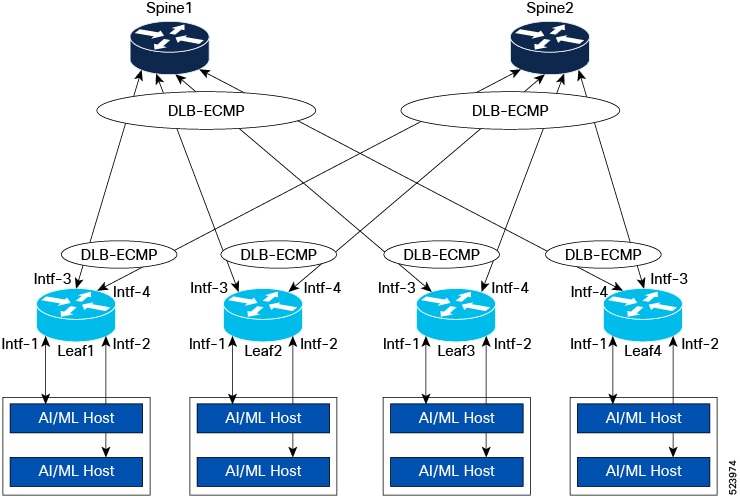
The Dynamic Load Balancing (DLB) topology is useful in AI/ML training networks. These networks use the spine-leaf architecture as shown in the image.

In this topology, the AI and ML hosts (server) are connected to Interface-1 (Intf-1) and Interface-2 (Intf-2) of the leaf switches. Intf-3 and Intf-4 of the leaf switches are connected to two spines, Spine 1 and Spine 2. While synchronizing data, for example, training data, across the AI/ML hosts, the training data gets transferred through the spine-leaf fabric among all the hosts.

Workflow

Figure 1. DLB Topology

Result

As leaf switches are connected to spines with more than one link, ECMP is used to load-share traffic across multiple links. The AI/ML training networks have fewer traffic flows with unique 5-Tuple IP fields compared to traditional networks. As such flows are limited in number, the traditional ECMP can lead to polarization issues, meaning suboptimal use of redundant paths, which in turn can lead to over-subscription on some links or interfaces. This can result in overall low throughput in the fabric.

The ECMP DLB feature resolves link utilization issues such as no utilization or under utilization by ensuring proper usage of all links. When you enable DLB on all the ports that are part of an ECMP group, a link with the lowest Tx link utilization is chosen among the available links for every new flow. In the image, DLB is enabled on Intf-3 and Intf-4. If intf-3 is fully utilized, and a new flow arrives, intf-4 gets selected. In traditional ECMP, the possibility is that Intf-3 gets picked even though it is oversubscribed.

ECMP DLB also supports static pinning, which allows users to pin traffic coming from a particular source port to be always sent on a specific DLB enabled egress port. In the image, for traffic taking a DLB ECMP group in which Intf-3 and Intf-4 are members, the user can pin traffic from Intf-1 to always take Intf-3 and Intf-2 to always take Intf-4.

Dynamic Load Balancing feature in NX-OS releases

Starting from Cisco NX-OS Release 10.5(1)F, the Layer 3 ECMP Dynamic Load Balancing (DLB) feature provides support to efficiently load balance traffic, depending on the current state of utilization of the outgoing links. The support for this feature is provided on different Nexus switches through different NX-OS releases as shown in the table.

Switches

Release

Nexus CloudScale switches such as 9300-FX3, -GX, -GX2, -H1, and -H2R TORs

Cisco NX-OS Release 10.5(1)F

Silicon One switches—only on N93C64E-SG2-Q and N9364E-SG2-O switches

Cisco NX-OS Release 10.5(3)F

Dynamic Load Balancing on CloudScale switches

The concepts, guidelines, limitations, and configuration sections for CloudScale switches differ from the Silicon One switches and are described in this section.

Key concepts of Dynamic Load Balancing on CloudScale switches

This section comprises the main concepts that you need to know before configuring DLB on CloudScale switches.

Fast link failover

Fast link failover in the context of DLB ECMP load balancing on Nexus 9000 switches is a feature that allows the network to quickly respond to and recover from physical link failures. When a link used in an ECMP group fails, fast link failover ensures that the traffic is immediately redirected to the remaining operational links the link failover is detected by the hardware, and new link is selected from the remaining links automatically. As this occurs at the hardware layer, this provides faster convergence.

Dynamic Rate Estimator

A Dynamic Rate Estimator (DRE) is implemented in the hardware for measuring the current link utilization. The role of the DRE withing DLB is to provide real-time estimation of the traffic rate on various links. This real-time analysis allows the switch to make more informed decisions when distributing traffic to ensure that no single path becomes over saturated. When a new flow starts, the DLB uses the DRE metric to determine the least utilized path within the multiple paths in a DLB ECMP Group.

At any point in time, a DLB-enabled interface can be at one of the DRE levels from level-1 to level-7 based on the utilization of the link and configured DRE thresholds. Level-1 indicates lowest utilization and level-7 the highest utilization. During the DLB decision, always a link with lowest DRE level is selected. If more than one link is available with the same lowest DRE level, one of the links among them is selected randomly. For more information, see Calculate Link Utilization Level.

Modes

Layer 3 ECMP Dynamic Load Balancing supports any one of the following modes in global configuration:

  • Flowlet Load Balancing (FLB) – In this mode, load balancing occurs at flowlet level based on DRE metrics. This is the default mode.

  • Per-packet Load Balancing (PLB) – In this mode, the load balancing decision occurs at a per-packet level instead of the flowlet level.

Flowlet Load Balancing

Flowlets are bursts of packets from a flow, identified by their 5-tuple (or selected fields from the packet), that are separated by large enough gaps such that they can be routed independently without causing reordering.

The flowlet is a unit of traffic used when the DLB works in flowlet mode. For each flowlet, the best outgoing port is picked by the hardware, which has the least Tx utilization, indicated by a per-port DRE. If utilization is the same for all ports, one of the ports is randomly selected.

Once a port is selected for a flowlet, the same port is used for all subsequent packets from that flow. A new port selection is triggered only when there is an inter-packet gap in the flowlet that is greater than the configured flowlet-aging time or when the currently utilized port goes down.

Per-packet Load Balancing

Per-packet Load Balancing can be used for scenarios where the end points (for example, Smart NICs) allow for packet re-ordering. This mode distributes traffic across the available links in a DLB ECMP and helps spread traffic out, reducing network congestion. For each packet in a flow, a new output port selection happens. So, the packets from the same flow can be sent across multiple paths causing packet re-ordering. The port selection process uses DRE, that is, port with the least DRE metric is selected for every packet. If DRE is the same for all ports, one of the ports is randomly selected.

Static pinning

Static pinning is supported on DLB. In static pinning, a source port is pinned to a destination port that is part of a DLB enabled ECMP group. All the traffic from this source port is sent to the pinned destination port if this port is part of the DLB ECMP group used for this flow. Front panel ports (including breakout ports) can be used as static pinning source interface. Destination interface must be part of the DLB interfaces list.

When static pinning is enabled, static pinning overrides the DLB DRE-based port selection.

When a DLB port is used as destination port in static pinning, this port cannot be removed from the dlb-interface list unless the static pinning configuration for that port is removed.


Note


You can enable either static pinning or PLB mode. You cannot enable both at the same time.


Note


Beginning with Cisco NX-OS Release 10.5(2)F, the system supports up to 512 static pinning pairs.


Guidelines and Limitations for Dynamic Load Balancing on CloudScale switches

The guidelines and limitations for Layer 3 Dynamic Load Balancing on CloudScale switches are categorized into 4 sub sections that include

ECMP group

  • The decision to enable DLB should be done during ECMP group creation when these three conditions are met:

    • All members of an ECMP group are in the DLB-enabled interface list. If an ECMP group has one or more members that are not in the DLB interface list, regular ECMP is used for that ECMP group.

    • The members of an ECMP group can only be Layer 3 interfaces. Break-out ports, sub interfaces, SVI, and port-channels cannot be members of a DLB ECMP group.

    • ECMP is not weighted ECMP or Resilient ECMP.

  • Resilient ECMP and DLB features cannot be enabled together. For more information about resilient ECMP, refer to Cisco Nexus 9000 Series NX-OS Interfaces Configuration Guide.

  • For weighted ECMP groups, DLB is not applicable. For more information about weighted ECMP or UCMP, see Unequal Cost Multipath (UCMP) over BGP.

  • The show routing hash command does not work for routes using DLB ECMP Groups. This is because, when DLB is enabled, the port selection is done dynamically based on the link utilization instead of using static hash.

  • In cases where the DLB ECMP scale is reached or if, due to any condition, DLB cannot be enabled, then the regular ECMP without DLB is used.


Note


When one of the member ports in a DLB-enabled ECMP group goes down, the hardware immediately stops sending traffic through that port. This ensures minimal traffic loss during link failures.


Feature support

  • This feature is supported only on

    • Layer 3 physical interfaces,

    • IP routed fabrics and VXLAN fabrics, and

    • 9300-FX3, -GX, -GX2, H1, and H2R TOR platforms.

  • This feature is not supported on TORs that have line-card expansion modules (LEM) and N9K-C9408.

  • Egress Access-list policies, Egress QoS policies and TX SPAN configured on the egress interfaces are not applied for flows using ECMP DLB.

  • MPLS/GRE tunnel do not use DLB ECMP, they fall back to regular ECMP.

  • When you use this feature, if the DLB ECMP scale is high, we recommend using the system pic-core option. After using the system pic-core option, a switch reload is required. For more information, see Configuring BGP PIC Core.

  • DLB is not applicable to traffic flows to which policy-based routing (PBR) logic is applied. These flows use the regular ECMP feature.

  • MTU should be configured on all DLB-enabled interfaces based on the maximum size of the packets used in the DLB flows. Otherwise, as output drops, traffic is also dropped on egress interfaces.

  • Only IPv4 and IPv6 unicast traffic is supported.

Ports

  • Breakout ports, port-channels, SVIs, port-channel members, or sub-interfaces cannot be a part of the DLB-enabled interface list.

  • A maximum of 63 physical ports can be a part of the DLB interface list.

DLB parameters

This section lists the guidelines for DLB-related parameters such as MAC, aging, DRE thresholds, mode, and static pinning.

  • A switch reload is required when a DLB interface list is configured for the first time or modified for the configuration to take effect.

  • Choose the flowlet-aging time based on the round-trip time in the fabric; otherwise, the flows can be re-ordered.

  • All the DLB-related parameters under DLB configuration are programmed in hardware only when there is a valid applied DLB interface list.

  • When any one of the MAC, aging, mode, or DRE threshold configurations are removed, all parameters are set to default values.

  • After adding a port to the DLB interface list, if the port is either modified to be a breakout port or added to be part of a PO or a sub interface is created on this interface, DLB is no longer enabled for ECMP groups that contain the port. The user should remove the port from the DLB interface list.

  • Any change to the DRE thresholds can have a momentary traffic impact on DLB-enabled flows. This is a disruptive trigger.

  • The DLB MAC configuration should be the same on all the nodes in the fabric. If the DLB MAC configuration is changed on a switch without changing this in the connected nodes in the fabric receiving these flows, the traffic is dropped.

  • Static pinning and Per-packet DLB modes cannot be supported at the same time.

  • Breakout ports can be a part of the static pinning source interfaces. However, sub-interfaces and port-channels cannot be part of the static pinning source interfaces.

Configure Dynamic Load Balancing on CloudScale switches

To configure Layer 3 Dynamic Load Balancing on CloudScale switches, run the commands listed in this section in the hardware profile dlb sub mode.

Before you begin

Use the configure terminal command to ensure that you are in the global configuration mode.

Procedure


Step 1

Use the hardware profile dlb command to enter the hardware profile dynamic load balancing mode.

Example:

switch(config)# hardware profile dlb

Step 2

Use the dlb-interface <interface_range> command to specify the list of interfaces for which DLB is to be enabled. Add comma-separated interfaces. This list cannot be changed dynamically, and requires switch reload for the interface list to be effective.

Note

 
  • Any change in interface list requires reload for the configuration to be effective.

  • To verify the current applied list, use the show hardware profile dlb command.

  • Incremental addition or deletion to the interface-list is not supported. The configuration is replaced with the newly provided interface list.

Example:

switch(config-dlb)# dlb-interface Eth1/5,Eth1/7,Eth1/17,Eth1/21,Eth1/26

Step 3

(Optional) Enter the dre-thresholds [level-1 percentage_1 | level-2 percentage_2 | level-3 percentage_3 | level-4 percentage_4 | level-5 percentage_5 | level-6 percentage_6 | level-7 percentage_7] command in DLB mode to define DRE levels from level 1 to level 7. The value configured per level is the percentage utilization range of port bandwidth from the previous level. The total of all the levels specified must be equal to 100. If you do not configure the DRE threshold levels, the following default values are used: 30, 20, 15, 10, 10, 10, and 5.

For more information about DRE level link utilization, see Calculate Link Utilization Level.

Example:

switch(config-dlb)# dre-thresholds level-1 15 level-2 20 level-3 30 level-4 15 level-5 10 level-6 5 level-7 5

Step 4

(Optional) Use the flowlet-aging usec command in DLB mode to configure flowlet aging time in usecs. The default is 500 usecs and the maximum value is 2 seconds or 2000000 usecs.

Note


Ensure that you choose the flowlet aging time with utmost care, else the flows can get re-ordered.

Example:

switch(config-dlb)# flowlet-aging 600

Step 5

(Optional) Use the mac-address macaddr command in DLB mode to configure the DLB MAC address. This address is used as next-hop MAC address for all the flows using DLB. This DLB MAC is used to re-write the Destination MAC for DLB flows instead of the learned next-hop MAC address for the egress interfaces.

The guidelines and limitations include:

  • If you do not configure this command, the default DLB MAC address used during the feature initialization is used as the default DMAC, that is, 00:CC:CC:CC:CC:CC.

  • If you configure the DLB MAC address, then the default MAC is replaced with the newly configurable MAC address.

  • All packets received on the switch with this DLB MAC as destination MAC are treated as routed packets.

  • When applying this configuration, ensure that all other nodes in the fabric are configured with the same DLB MAC.

  • If there is no dlb-interface list applied, then the DLB MAC cannot be used as additional router MAC.

  • Broadcast and multicast MAC addresses cannot be configured as DLB MAC address.

Example:

switch(config-dlb)# mac-address aa:bb:cc:dd:ee:ff

Step 6

(Optional) Enter the mode [flowlet | per-packet] command in DLB mode to enable either flowlet or per-packet DLB mode. The default mode is flowlet.

Note


For per-packet mode, static pinning cannot be enabled.

Example:

switch(config-dlb)# mode flowlet

Step 7

(Optional) Use the static-pinning command in DLB mode to configure the static pinning feature.

Note


For static pinning, per-packet mode cannot be enabled.

Example:

switch(config-dlb)# static-pinning

Step 8

(Optional) Use the source source physical interface destination destination physical interface command to configure source and destination interfaces for static pinning. However, these should be physical interfaces only, that is, the front panel Ethernet interfaces. SVI, port-channels, or sub-interface cannot be source or destination interface.

The guidelines and limitations include:

  • The destination interface should be a part of the DLB applied or configured interface-list, but a source interface cannot be a part of this list.

  • Beginning with Cisco NX-OS Release 10.5(2)F, interface in the DLB applied or configured interface-list can also be used as static pinning source interface.

  • If the same source interface is used for two configurations, then the first destination interface gets replaced with the second destination interface, as the source interface is the same.

  • Break-out ports can be configured as source interface.

  • When no breakout or break-out operations are performed on the ports, the user should update the DLB or static pinning configuration.

  • An interface cannot be deleted from the DLB interface list if it is configured as a destination interface in static pinning. To delete it, first remove the static pinning configuration and then delete the interface from the DLB interface list.

Example:

switch(config-dlb-static-pinning)# source ethernet 1/1 destination ethernet 1/2

Calculate Link Utilization Level

The link utilization at each level is calculated as follows:

  • Current Level Range Start: Sum of % values specified for all the previous levels.

  • Current Level Range End: Current Level Range Start + Current Level value.

For example:

Level-1: 30, Level-2: 20, Level-3: 15, Level-4: 10, Level-5: 10, Level-6: 10, Level-7: 5.

  • Level-5 Range Start: 75% (30 + 20 + 15 + 10)

  • Level-5 Range End: 85% (75 + 10)

Guidelines for DRE Threshold Levels

A few guidelines and limitations related to Dynamic Rate Estimator (DRE) threshold levels are as follows:

  • The above-mentioned logic applies to a scenario when any level is zero (0). You add up the levels, then that level will have the same range as the previous level with the non-zero value.

    For example,

    Level-1: 30, Level-2: 0, Level-3: 35, Level-4: 10, Level-5: 10, Level-6: 10, Level-7: 5.

    • Level-2 Range: Level 2 will be the same as Level-1, that is 30%.

  • If all previous values are zero, the current level will be the first non-zero level specified.

    For example,

    Level-1: 0, Level-2: 0, Level-3: 0, Level-4: 0, Level-5: 50, Level-6: 30, Level-7: 20.

    • In this case, the starting level for link utilization will be Level-5.

  • Specify all the levels. If a few levels are not specified, they will be considered as zero.

    For example,

    Level-1: 50, Level-2: 0, Level-3: 0, Level-4: 0, Level-5: 0, Level-6: 30, Level-7: 20

    • Levels 2, 3, 4, and 5 are considered zero.

Dynamic Load Balancing on Silicon One switches

The concepts, guidelines, limitations, and configuration sections for Silicon One switches differ from the CloudScale switches and are described in this section.

Key concepts of Dynamic Load Balancing on Silicon One switches

This section comprises the main concepts that you need to know before configuring DLB on Silicon One switches.

Flowlet Load Balancing

Flowlets are bursts of packets from a flow, identified by their 5-tuple (or selected fields from the packet), that are separated by large enough gaps such that they can be routed independently without causing reordering.

When DLB works in flowlet mode and a port is selected for a flowlet, the same port is used for all subsequent packets from that flow. This is called as Flowlet Load Balancing (FLB).

A new port selection is triggered only when there is an inter-packet gap in the flowlet that is greater than the configured flowlet-aging time or when the currently utilized port goes down. The new port selection happens at the start of each flowlet interval, ensuring uniform distribution of traffic across all links of the DLB ECMP group. The port selection process tries to uniformly distribute the packets across all the available ports at the flowlet boundary. The port selection can either be based on link utilization or be random.

Per-packet Load Balancing

Per-packet Load Balancing (PLB) can be used for scenarios where the endpoints, for example, Smart NICs, allow for packet re-ordering. This mode distributes traffic packet by packet across all the available links in a DLB ECMP group and helps spread out the traffic, reducing the network congestion. This mode offers the most optimal usage of the network bandwidth and faster end-to-end latency. For each packet in a flow, a new output port is selected. So, the packets from the same flow are sent across multiple paths potentially causing packet re-ordering.

The port selection process tries to uniformly distribute the packets across all the available ports. The port selection can either be based on link utilization or be random.

Policy-driven DLB

Policy-driven dynamic load balancing is a method used to manage the network traffic by dynamically classifying the ingress traffic flows based on predefined interface QOS policies and determining the load balancing mode for the flow.

Policies consist of rules that define when and how the dynamic load balancing should occur. These rules can be enabled or disabled, providing flexibility in managing the network traffic forwarding. When the traffic does not match the QOS policy rules with actions of flowlet or per-packet, policy override takes place and the traffic uses regular ECMP.

The policy- driven DLB mode relies on the QOS policy match, and the two types of policy-driven DLB we support include

  • Simple policy-driven DLB—Policy would only drive either flowlet or per-packet DLB behavior. The dlb mode in QoS Policy should match the mode in hardware profile dlb configuration.

  • Policy-driven DLB with mixed mode—In this flexible mode of operation, system can support both flowlet and per-packet forwarding simultaneously. The ECMP scale in this profile is reduced from 512 ECMP groups to 256 ECMP groups.

Modes

Layer 3 ECMP Dynamic Load Balancing supports any one of the 7 modes in global configuration on Silicon One switches.

  • Flowlet Load Balancing (FLB)—In this mode, load balancing occurs at flowlet level based on port load. This is the default mode when DLB is enabled.

  • Per-packet Load Balancing (PLB)—In this mode, the load balancing decision occurs at a per-packet level instead of the flowlet level. This mode provides the most throughput with even utilization across all member ports but can result in packet reordering.

  • Policy-driven flowlet—QoS set dlb mode option should be flowlet. When the mode is not matching the policy, applied interfaces go to err-disabled state.

  • Policy-driven per-packet—QoS set dlb mode option should be per-packet. When the mode is not matching the policy, applied interfaces go to err-disabled state.

  • Policy-driven mixed (default ecmp)—Without QoS Policy, we have regular ECMP based forwarding. We can have different QoS policies driving both flowlet and per-packet behavior.

  • Policy-driven mixed default flowlet—By default the traffic takes flowlet DLB forwarding. A QoS policy can override the behavior to support per-packet forwarding.

  • Policy-driven mixed default per-packet—By default the traffic takes per-packet DLB forwarding. A QoS policy can override the behavior to support flowlet-based DLB forwarding.

Choose and set the modes based on your traffic and scale requirements. In a default mode of operation, where you want DLB for all the traffic that is coming in on all the ports, use FLB or PLB. When you need DLB for selective traffic, for example, RDMA-over Converged Ethernet (RoCE)-based traffic and not for the regular traffic, use the mixed policy-driven DLB mode.

Fast link failover

Fast link failover in the context of DLB ECMP load balancing on Silicon One switches is a feature that allows the network to quickly respond to and recover from physical link failures. When a link used in an ECMP group fails, fast link failover ensures that the traffic is immediately redirected to the remaining operational links the link failover is detected by the hardware, and new link will be selected from the remaining links automatically. As this is done at the hardware layer, this provides faster convergence.

Hierarchical Weighted ECMP with DLB

In a spine-leaf topology, normally the traffic gets distributed equally across both the spines. However, when there are link failures in the fabric, this can result in congestion on one of the spines if not addressed at the ingress leaf. This problem can be resolved by considering link failures to account for the traffic that hits the spine on the ingress leaf using Weighted ECMP (WCMP).

The hierarchical WCMP provides the ability to pick the spines with full bandwidth towards a leaf into one DLB ECMP group and spines with partial bandwidth into another DLB ECMP group. The DLB is performed only among the members of the individual DLB ECMP group.

The hierarchical Weighted ECMP with DLB feature solves the problem while ensuring uniform distribution across all the links towards the spines after weighted distribution to maximize the link utilization.

For more information regarding Weighted ECMP, also known as UCMP, refer to the Unequal Cost Multipath (UCMP) over BGP section in the Cisco Nexus 9000 Series NX-OS Unicast Routing Configuration Guide on Cisco.com.

Example

The image depicts a topology where 3 spines connected to 4 leafs which are in turn connected to individual AI/ML hosts. The eBGP is configured on every link connecting Leafs to Spines. Leafs advertise routes with weights to the spine and the spines advertise cumulative weights.

Consider a 100-Gig traffic that is supposed to egress from Leaf 1 and ingress to Leaf 4 through Spines 1, 2, and 3. In the traditional way, it goes over a 6-way ECMP of all the links to Spine 1, 2, and 3. In a scenario where one link is down from Spine 3 to Leaf 4, the bandwidth available on that link is reduced compared to the bandwidth available on other Spines. This can result in congestion on Spine 3.

Figure 2. Hierarchical WCMP

This issue is resolved using hierarchical WCMP of DLB ECMP group. This provides the ability to pick Spines with full bandwidth towards a leaf into one group (DLB ECMP Group1) and Spines with partial bandwidth into another group (DLB ECMP Group2) and these together form the Weighted ECMP group and the FLB is performed among the members of this group. The WCMP dynamically picks Spines 1 and 2 for 80% traffic based on their bandwidth and Spine 3 for 20% of the traffic destined towards Leaf4. Thus, the traffic of weight 20 each is carried through the 2 links each of Spine 1 and 2 to Leaf4 while the traffic of weight 10 each is carried to 2 links of Spine 3 and delivered through one active link carrying traffic of weight 20 to Leaf 4.

In summary, the WCMP with DLB ECMP feature uses dynamic load balancing to select the best link based on link utilization.

IP load sharing

The flowlet is uniquely identified using the parameters configured in the ip load-sharing command. By default, the parameters used are source IP, destination IP, destination port, source port, and IPv4 protocol.

For more information about Configuring ECMP Load Balancing including Silicon One switches, refer to Interfaces Configuration Guide on Cisco.com.

Guidelines and limitations for Dynamic Load Balancing on Silicon One switches

The guidelines and limitations for Layer 3 Dynamic Load Balancing on Silicon One switches are divided into four sub-sections.

Feature support

  • Layer 3 ECMP DLB is supported only on

    • Layer 3 physical interfaces,

    • IP routed fabrics and VXLAN fabrics, and

    • from 10.5(3)F, on N9364E-SG2 switches.

  • If the DLB ECMP scale is high, use the system pic-core option and then reload the switch. For more information, see Configuring BGP PIC Core.

  • Configure the MTU on all DLB-enabled interfaces based on the maximum packet size used in the DLB flows. If not, the traffic drops when the output drops on the egress interfaces.

  • Only IPv4 and IPv6 unicast traffic is supported.

  • Static pinning is not supported.

Ports

  • Port-channels, SVIs, port-channel members, or sub-interfaces cannot be part of the DLB interface list.

  • The DLB interface list can include up to 63 physical ports. The dlb interface all option allows all physical ports in the system to support DLB.

  • We support only one IPv4, one IPv6 nexthop, and one IPv6 link-local nexthop on a DLB interface.

ECMP

  • The maximum support for members in a DLB ECMP is a 127-way ECMP.

  • DLB policy-driven mixed mode reduces the supported scale from 512 to 256 groups.

  • DLB is enabled on the ECMP group in the hardware during the group creation provided the listed conditions are met which include:

    • All members of an ECMP group are in the DLB-enabled interface list. If an ECMP group has one or more members that are not in the DLB interface list, regular ECMP is used for that ECMP group.

    • When you choose the interface-list all option, all Layer 3 physical interfaces including break-out interfaces on the switch can be the members of a DLB ECMP group.

    • Sub-interfaces, SVIs, and port-channels cannot be members of a DLB ECMP group. If any of these are members of an ECMP group, then DLB is not enabled for that group.

    • ECMP is not Resilient ECMP.

  • Resilient ECMP and DLB features cannot be enabled together. For more information about resilient ECMP, refer to Cisco Nexus 9000 Series NX-OS Interfaces Configuration Guide.

  • For the traditional weighted ECMP groups, DLB is not applicable. For more information about weighted ECMP or UCMP, see Unequal Cost Multipath (UCMP) over BGP.

  • The show routing hash command does not work for routes using DLB ECMP Groups. This is because, when DLB enabled, the port selection is done dynamically based on the link utilization instead of using static hash.


Note


When one of the member ports in a DLB-enabled ECMP group goes down, the hardware immediately stops sending traffic through that port. This ensures minimal traffic loss during link failures.


DLB parameters

The DLB parameters include the parameters such as aging and mode.

  • When you configure a DLB interface list for the first time or modify it, reload the switch for the configuration to take effect.

  • Choose the Flowlet-aging time based on the round-trip time in the fabric; otherwise, the flows can be re-ordered.

  • Changing between DLB modes is allowed, but requires a switch reload. For DLB policy-based actions applied to the interfaces, ensure that the QoS configuration matches the new dlb mode .

  • When you remove parameters such as aging, mode, decay-factor, sampling-interval, and load-awareness, they reset to their default values.

  • After adding a port to the DLB interface list, if the port is either modified to be a breakout port or added to be a part of a PO or if a sub interface is created on this interface, DLB is no longer enabled for ECMP groups that contain the port. Remove the port from the DLB interface list.

Configure Dynamic Load Balancing on Silicon One switches

Run the commands listed in this section under the hardware profile dlb sub mode to configure Layer 3 Dynamic Load Balancing on Silicon One switches.


Note


For the policy-driven DLB to work, perform the DLB configuration mentioned in this section and then configure the QoS policy with set dlb mode. See the Configure Policy-driven Dynamic Load Balancing section in the Cisco Nexus 9000 Series NX-OS Quality of Service Configuration Guide on Cisco.com.


Before you begin

Use the configure terminal command to ensure that you are in the global configuration mode.

Procedure


Step 1

Use the hardware profile dlb command to enter the hardware profile dynamic load balancing mode.

Example:

switch(config)# hardware profile dlb

Step 2

Use the dlb-interface [interface_range | all] command to specify the list of interfaces for which DLB is to be enabled. Add comma-separated interfaces. This list cannot be changed dynamically, and requires switch reload for the interface list to be effective.

Note

 
  • Any change in interface list requires reload for the configuration to be effective.

  • To verify the currently applied list, use the show hardware profile dlb command.

  • Incremental addition or deletion to the interface-list is not supported. The configuration is replaced with the newly provided interface list.

When you use the all option, all Layer 3 physical and Layer 3 breakout interfaces on the switch should be enabled for DLB; this requires a switch reload to be effective,

Under the effective dlb-interface all mode, newly added DLB-capable interfaces don't require a reload.

Example:

switch(config-dlb)# dlb-interface Eth1/5,Eth1/7,Eth1/17,Eth1/21,Eth1/26
switch(config-dlb)# dlb-interface all

Step 3

(Optional) Enter the flowlet-aging usec command in DLB mode to configure Flowlet aging time in microseconds (usec ). The default value is 255 microseconds, and the maximum value is 1024 microseconds.

Note


Choose the Flowlet aging time carefully to prevent flow reordering.

Example:

switch(config-dlb)# flowlet-aging 600

Step 4

(Optional) Enter the mode [flowlet | per-packet | policy-driven] command in DLB mode to enable flowlet, per-packet, or policy-driven DLB mode. The default mode is flowlet .

Note


Reload the switch after changing the mode to apply the changes.

Example:

switch(config-dlb)# mode flowlet

Step 5

(Optional) Enter the mode policy-driven [flowlet | per-packet | mixed] command in DLB mode to enable QoS policies to drive flowlet, per-packet, or mixed policy-driven DLB mode. The mode set by the QoS policy should match the policy-driven DLB mode.

In mixed mode, both Flowlet and Per-packet are supported and the ECMP group scale is reduced from 512 to 256. Any one mode can be set as the default.

When the traffic does not match the QoS policy rules with actions of flowlet or per-packet, it defaults to using regular ECMP.

In the mixed mode, the default behavior can be modified using the configuration mentioned in Step 6.

For more information about the QoS policy match, refer to the Configure Policy-driven Dynamic Load Balancing chapter in the Cisco Nexus 9000 Series NX-OS Quality of Service Configuration Guide on Cisco.com.

Note


If you change the mode, reload is required.

Example:

switch(config-dlb)# mode policy-driven mixed default ecmp

Step 6

(Optional) Enter the mode policy-driven mixed default [ecmp | flowlet | per-packet] command in DLB mode to modify the default behavior in the mixed mode. When the traffic does not match the QoS policy rules with actions of flowlet or per-packet, it chooses the default mode configured using this command. If no mode is configured, the configuration defaults to regular ECMP.

Note


If you change the mode, reload is required.

Example:

switch(config-dlb)# mode policy-driven mixed default ecmp

Step 7

(Optional) In DLB mode, use the decay-factor command to control how load balancing is influenced by the past traffic samples. Using a smaller value causes a faster response to changes as the data from the recent past is considered. A larger value results in a slower response to changes, as the emphasis is more on the historical data. The default value is 2. The decay-factor value ranges from 0 to 15.

Example:

switch(config-dlb)# decay-factor 2

Step 8

(Optional) Use the sampling-interval command in DLB mode to set the time interval for each port load sample collection in nanoseconds (nsecs). The default is 32000 nanoseconds. The range is 512 nanoseconds to 16,384,000 nanoseconds. The supported values are 512; 1000; 2000; 4000; 8000; 16,000; 32,000; 64,000; 128,000; 256,000; 512,000; 1,024,000; 2,048,000; 4,096,000; 8,192,000; and 16,384,000.

Example:

switch(config-dlb)# sampling-interval 32000 nsecs

Step 9

(Optional) Enter the [no] load-awareness command in DLB mode to use port load for port selection. The default value is load-awareness .

To ignore the port load, use the no load-awareness command.

Example:

switch(config-dlb)# load-awareness

Configuration examples for Dynamic Load Balancing

Use the sample configuration for Dynamic Load Balancing on CloudScale switches as a reference.

switch# configure terminal switch(config)# hardware profile dlb
switch(config-dlb)# dlb-interface Eth1/5,Eth1/7,Eth1/17,Eth1/21,Eth1/26 
switch(config-dlb)# dre-thresholds level-1 15 level-2 20 level-3 30 level-4 15 level-5 10 level-6 5 level-7 5 
switch(config-dlb)# flowlet-aging 600 
switch(config-dlb)# mac-address aa:bb:cc:dd:ee:ff
switch(config-dlb)# mode flowlet 
switch(config-dlb)# static-pinning 
switch(config-dlb-static-pinning)# source ethernet 1/1 destination ethernet 1/2

Use the sample configuration for Dynamic Load Balancing on Silicon One switches as a reference.

switch# configure terminal 
switch(config)# hardware profile dlb
switch(config-dlb)# dlb-interface all
switch(config-dlb)# flowlet-aging 600
switch(config-dlb)# mode flowlet
switch(config-dlb)# decay-factor 2
switch(config-dlb)# sampling-interval 32000 nsecs
switch(config-dlb)# load-awareness

Verify the Dynamic Load Balancing configuration

Choose one of the commands from the table to view information about the Dynamic Load Balancing (DLB) configuration. The table lists the show commands for DLB and their purposes.

Command

Purpose

show hardware profile dlb

Displays the DLB configuration.

Note

 
  • Configured Interface-list—Lists current interfaces configured using the Command Line Interface. Post reload, this list populates the applied interface-list.

  • Applied Interface-list—Provides the list of interfaces that are being used currently for DLB.

  • Configured DLB mode—Provides the configured DLB mode. After reloading the switch this becomes the Applied DLB mode.

  • Applied DLB mode—Provides the DLB mode currently in use.

show system config reload-pending

Displays the reload-pending configuration. For DLB, it displays the interface-list that is pending application if changes were made to the interface-list configuration.


Note


The show routing hash command does not work for routes that use DLB ECMP Groups.


Show command output

You can view the sample output of the show hardware profile dlb command on CloudScale platforms.

switch# show hardware profile dlb 
DLB Configurations: 
===================
 
 
Enabled:                yes
Mode:                   flowlet
Mac-address:            aa:bb:cc:dd:ee:ff
Flowlet aging time:     600 usec(s)
DRE-thresholds:
        Level-1:15
        Level-2:20
        Level-3:30
        Level-4:15
        Level-5:10
        Level-6:5
        Level-7:5
DLB interface list: 
--------------------
 
Configured Interface-list (size: 5):
        Eth1/5,Eth1/7,Eth1/17,Eth1/21,Eth1/26
 
Applied interface-list (size: 5): 
        Eth1/5,Eth1/7,Eth1/17,Eth1/21,Eth1/26
 
Static-pinning enabled: yes
 
DLB static-pinning pairs: 
---------------------------
 
static-pinning pairs (1):
 
        source: Eth1/1    dest: Eth1/5

You can view the sample output of the show hardware profile dlb command on Silicon One platforms.

switch# show hardware profile dlb 
DLB Configurations: 
===================


Enabled: yes
Configured DLB Mode: flowlet
Applied DLB Mode: flowlet
Flowlet aging time: 512 usec(s)
Decay Factor: 2 
Sampling Interval: 32000 nsec(s)
Load Awareness: True
DLB interface list: 
--------------------
Configured Interface-list : all

Applied Interface-list : all

switch# 

You can view the sample output of the show system config reload-pending command for DLB on the Nexus 9000 series switches, both CloudScale and Silicon One.

switch# show system config reload-pending 
 
Following config commands require copy r s + reload : 
======================================================
0       hardware profile dlb ; dlb-interface Eth1/5,Eth1/7,Eth1/17,Eth1/21,Eth1/26
======================================================