Overview
Steps to install and remove OSFP and QSFP modules.
This section provides the installation, cabling, and removal instructions for the Quad Small Form-Factor Pluggable transceiver modules. Refer to the Cisco Transceiver Modules Compatibility Information for additional details on optical transceivers.
Statement 1079—Hot Surface
This icon is a hot surface warning. To avoid personal injury, do not touch without proper protection.

The transceiver module is a static-sensitive device. Always use an ESD wrist strap or similar individual grounding device when handling transceiver modules or coming into contact with system modules.
Protect the transceiver ports by inserting clean dust caps (8000-QSFP-DCAP) into any ports not in use or that do not have optical modules plugged in. If optical modules are plugged in but not in use, use the dust caps that were supplied with the optical modules to protect the TX and RX surfaces of the optical module.
Clean the optic surfaces of the fiber cables before you plug them back into the optical ports of another module.
The switch ships with dust caps plugged in. We highly recommend you keep the dust caps plugged in until you are ready to plug an optic. The dust caps protect the ports from possible EMI interference and also avoid contamination due to dust collection.
To meet the EMI interference requirements, use the metal dust caps when the ports are not in use by optical modules.
Before you begin
Required tools and equipment:
-
Wrist strap or other personal grounding device to prevent ESD occurrences
-
Antistatic mat or antistatic foam to set the transceiver on
-
Fiber-optic end-face cleaning tools and inspection equipment
Procedure
| 1. | Attach an ESD wrist strap to yourself and a properly grounded point on the chassis or the rack. |
|
| 2. | Remove the transceiver module from its protective packaging. |
|
| 3. | Check the label on the transceiver module body to verify that you have the correct model for your network. Do not remove the dust plug until you’re ready to attach the network interface cable. The dust plug is not shown in the images. |
|
| 4. | Hold the transceiver by the pull-tab so that the identifier label is on the top. |
|
| 5. | Align the transceiver module in front of the module’s transceiver socket opening and carefully slide the transceiver into the socket until the transceiver contacts the socket electrical connector. 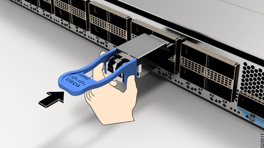
|
|
| 6. | Press firmly on the front of the transceiver module with your thumb to fully seat the transceiver in the module’s transceiver socket. 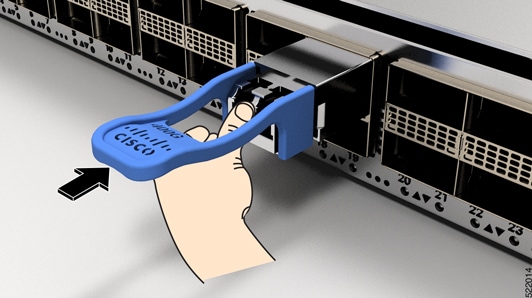
IMPORTANT: If the latch is not fully engaged, you might accidentally disconnect the transceiver module. |