Overview
Installing the switch using the NXK-ACC-RMK2-2RU rack-mount kit.
To install the switch, attach mounting brackets to the rack, install slider rails on the rear of the rack, slide the switch onto the slider rails, install the retainer brackets, and secure the switch to the rack with the retainer clips. Typically, the front of the rack is the side easiest to access for maintenance.
You supply the eight 10-32 or 12-24 screws required to mount the slider rails and switch to the rack.
Before you begin
-
Inspect the switch shipment to ensure that you have everything ordered.
-
Verify that the switch rack-mount kit includes these parts:
-
Rack-mount brackets (2)
-
Rack-mount front-mount brackets (2)
-
Rack-mount slider rails (2)
-
Rack-mount retainer clips (2)
-
Phillips countersink screws (12)
-
Flat head screws M4 (6)
-
Flat head screws M3 (4)
-
-
The rack is installed and secured to its location.
Procedure
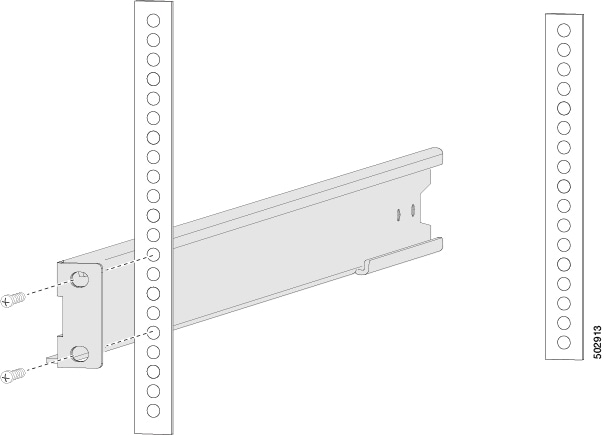
| 1. | Install two rack-mount brackets to the rack.
|
|
| 2. | If you are not installing the chassis into a grounded rack, attach a customer-supplied grounding wire to the chassis as explained in Ground the chassis . If you are installing the chassis into a grounded rack, skip this step. |
|
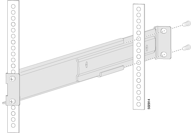
| 3. | Install the slider rails on the rack or cabinet.
|
|
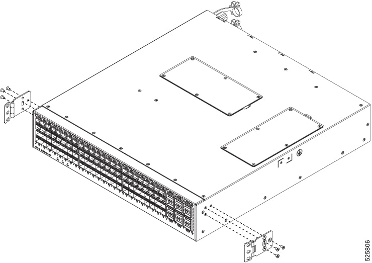
| 4. | Insert the switch into the rack and attach it.
|
|
| 5. | Insert the switch into the rack and attach it.
|
|
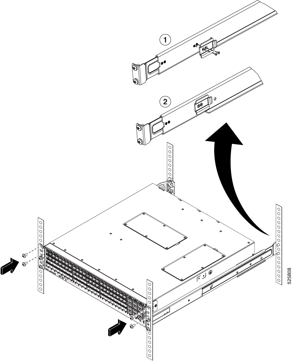
| 6. | Rotate one front mount bracket to align with the rack (see the figure). 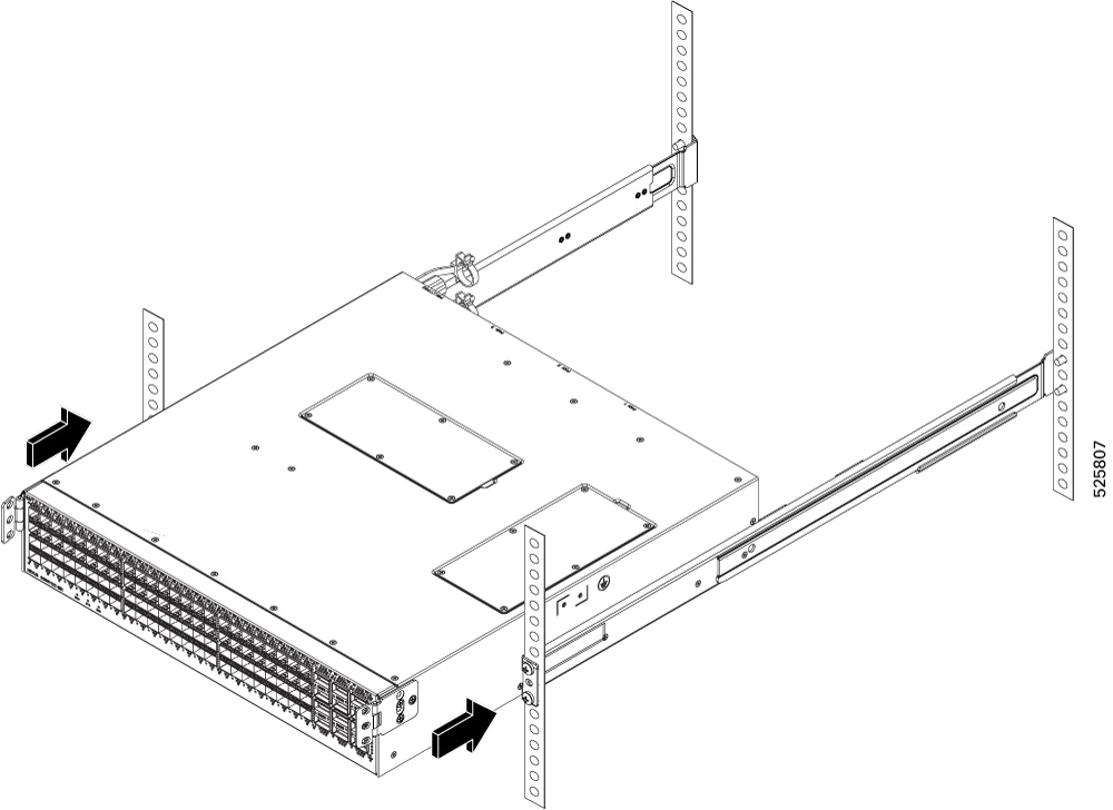
|
|
| 7. | Insert the retainer clip to hold the chassis in place.
|
|
| 8. | If you attached a grounding wire to the chassis grounding pad, connect the other end of the wire to the facility ground. |