Overview
How to ground the switch chassis.
The switch chassis is automatically grounded when you properly install the switch in a grounded rack with metal-to-metal connections between the switch and rack.
Provide an electrical conducting path between the product chassis and the metal surface of the enclosure or rack in which it is mounted or to a grounding conductor. To ensure electrical continuity, use thread-forming type mounting screws that remove any paint or non-conductive coatings and establish a metal-to-metal contact. Remove any paint or other non-conductive coatings on the surfaces between the mounting hardware and the enclosure or rack. Clean the surfaces and apply an antioxidant before installation.
Ground the rack if using LVDC power supplies. If using AC or HVDC power supplies, the power cord for the AC power supplies provides grounding for the chassis. For supplemental grounding or bonding, attach a customer-supplied grounding cable to the chassis ground pad.
Ground the chassis. If you are using a 2-post rack, attach a customer-supplied grounding cable. Attach the cable to the chassis grounding pad and the facility ground. If you are using a 4-post rack, ensure that your chassis is grounded through the rack mount system or the power cable (AC or HVDC).
Statement 1024—Ground Conductor
This equipment must be grounded. To reduce the risk of electric shock, never defeat the ground conductor or operate the equipment in the absence of a suitably installed ground conductor. Contact the appropriate electrical inspection authority or an electrician if you are uncertain that suitable grounding is available.
Before you begin
Statement 1046—Installing or Replacing the Unit
To reduce risk of electric shock, when installing or replacing the unit, the ground connection must always be made first and disconnected last.
If your unit has modules, secure them with the provided screws.
Before you begin
Before you can ground the chassis, verify the earth ground contact has a solid connection to the data center building.
Procedure
| 1. | Use a wire-stripping tool to remove approximately 0.75 inch (19 mm) of the covering from the end of the grounding wire. We recommend 6-AWG wire for the U.S. installations. |
|||||||||
| 2. | Insert the stripped end of the grounding wire into the open end of the grounding lug. Use a crimping tool to crimp the lug to the wire. See the figure. Verify that the ground wire is securely attached to the grounding lug by attempting to pull the wire out of the crimped lug (tug test). 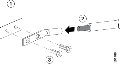
|
|||||||||
| 3. | Secure the grounding lug to the chassis grounding pad with two M4 screws, see figure 1. Tighten the screws to 11 to 15 in-lb (1.24 to 1.69 N m) of torque. |
|||||||||
| 4. | Prepare the other end of the grounding wire and connect it to the facility ground. |