Overview
Overview of N9396Y12C-SE1 switch.
The Cisco Nexus 9396Y12C-SE1 switch (N9396Y12C-SE1) is a 2-rack unit (RU), fixed-port switch designed for Top-of-Rack deployment in data centers. MACsec is supported on all ports. This switch has these ports:
-
96 1/10/25 SFP28 downlink ports. Half of the downlink ports support 50G.
-
12 40/100G QSFP28 uplink ports.
-
1 console port
-
1 management ports (one RJ-45 port or one SFP port)
-
1 USB port
Fan modules
This switch includes three fan modules with these airflow choices:
-
Port-side exhaust fan module with blue coloring (NXA-SFAN-160CFM2PE)
-
Port-side intake fan module with red coloring (NXA-SFAN-160CFM2PI)
| Port-side intake speed in % | Port-side exhaust speed in % |
|
|---|---|---|
| Typical/Minimum |
50% |
60% |
| Maximum |
95% |
95% |
When more than one fan module (two rotors) fails, a major alarm is raised and a graceful shut down is performed within two minutes, unless the fan module is restored.
The switch functions normally when only one fan tray fails. If more than one fan tray fails, the switch issues a warning and powers down within two minutes.
Power supply modules
Power supply modules (two: one for operations and one for redundancy [1+1]) with these choices:
-
1400-W port-side exhaust AC power supply with blue coloring (NXA-PAC-1400W-PE)
-
1400-W port-side intake AC power supply with red coloring (NXA-PAC-1400W-PI)
-
2000-W port-side intake DC power supply with red coloring (NXA-PDC-2KW-PI)
-
A mix of AC and DC power supplies in the same switch are supported for hot swapping purposes within a time limit of 15 minutes.
A mix of AC and DC power supplies in the same switch are supported for hot swapping purposes within a time limit of 15 minutes.
All the fan modules and power supplies must use the same airflow direction.
Features of the switch
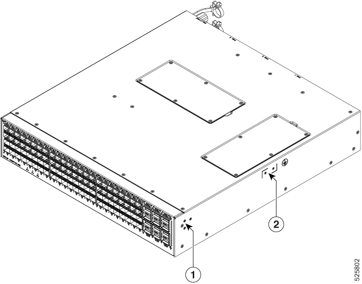
| 1 |
Screw holes for front mounting brackets (both left and right sides) |
2 |
Grounding pad |
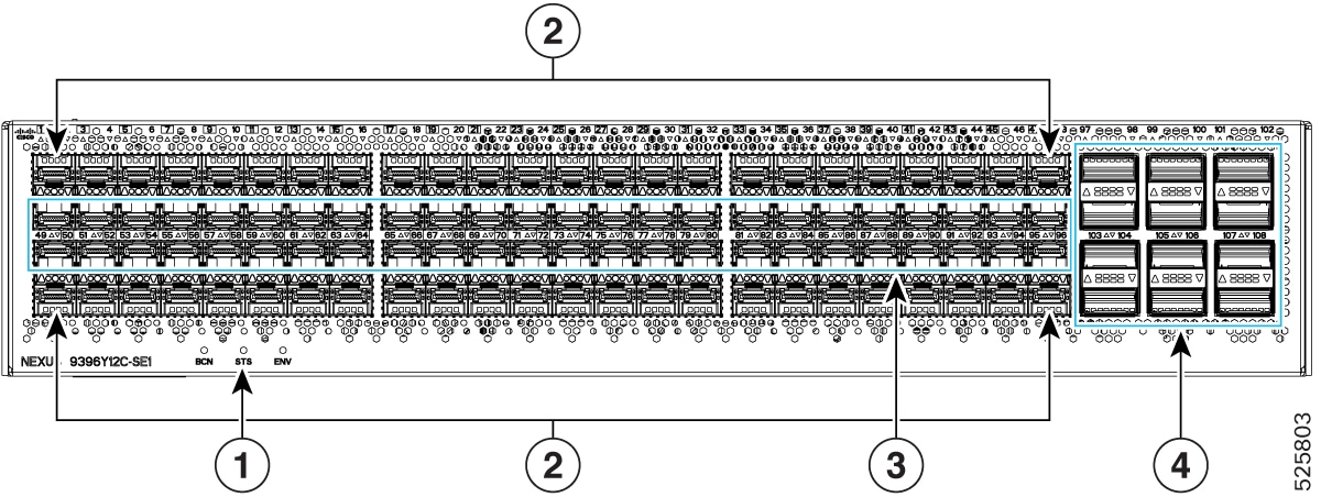
| 1 |
Beacon (BCN), Status (STS), and Environment (ENV) LEDs. |
3 |
48 x 1/10/25G (SFP28) downlink ports. |
| 2 |
48 x 1/10/25/50G (SFP28) downlink ports. | 4 |
12 x 40/100G QSFP28 uplink ports in a mirrored configuration. |
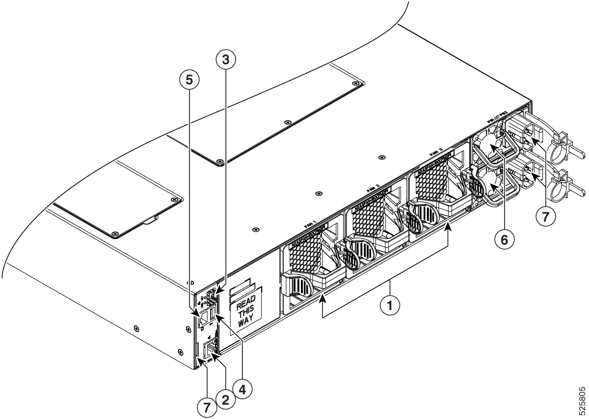
| 1 |
Fan modules (3) with slots numbered from 1 (left) to 3 (right) |
5 |
Console port (1) |
| 2 |
Management port (1—RJ-45 copper port) |
6 |
Power supply modules (1 or 2) (DC power supplies shown) with slots numbered 1 (top) and 2 (bottom) |
| 3 |
Management port (1—SFP optical port) |
7 |
Notch on both sides of the chassis at the end for rack mount supporting. |
| 4 |
USB port (1) |
Depending on whether you plan to position the ports in a hot or cold aisle, you can order the fan and power supply modules with port-side intake or port-side exhaust airflow. For port-side intake airflow, the fan and AC power supply modules have burgundy coloring. For port-side exhaust airflow, the fan and AC power supplies have blue coloring.
The fan and power supply modules are field replaceable and you can replace one fan module or one power supply module during operations so long as the other modules are installed and operating. If you have only one power supply installed, you can install the replacement power supply in the open slot before removing the original power supply.
All of the fan and power supply modules must have the same direction of airflow. Otherwise, the switch can overheat and shut down.
If the switch has port-side intake airflow (red coloring for fan modules), you must locate the ports in the cold aisle. If the switch has port-side exhaust airflow (blue coloring for fan modules), you must locate the ports in the hot aisle. If you locate the air intake in a hot aisle, the switch can overheat and shut down.