Guides through removing fans from Cisco 8500 Series Secure Routers, outlining safe removal steps to support maintenance and system cooling reliability.
Before you begin
Remove the chassis from the rack and place it on a table top to perform this task.
Perform the following steps before you begin the process of removing the fans :
-
Use an ESD-preventive wrist strap.
-
Back up the data that you want to save.
-
Remove the power supplies before you remove the chassis top cover.
Procedure
| 1. | Remove the chassis top cover by performing the following steps:
|
|
| 2. | Position the chassis so that you have the most comfortable access to the chassis to remove the fans. The fans are located at the rear of the chassis. |
|
| 3. | Unplug the six fan connectors from the motherboard. |
|
| 4. | Remove the three screws from the rear of the chassis as shown in the following figure. Note, use the screw specified in the Bill of Materials (BOM). 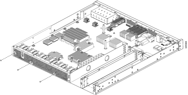
|
|
| 5. | Rotate the fan tray slightly rotate the top of the fan tray slightly into the chassis internals, and then lift it out of the chassis. |
|
| 6. | Reverse the order of fan removal to install the new fan tray. Ensure that all fans are connected and all screws for the fan tray and chassis cover are replaced prior to powering up the chassis. 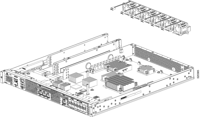
|