Guides users through rack installation by outlining guidelines, verifying rack dimensions, attaching front and rear rack-mount brackets, mounting devices, describing two-post and four-post methods, and managing cabling for a stable, organized setup.
Guidelines for rack installation
The Cisco 8500 Series Secure Routers can be installed in the following rack types:
-
Two-post rack, either 19 inch or 23 inch. Inner clearance (the width between the inner sides of the two posts or rails) must be at least 19 inches (48.26 cm). Airflow through the chassis is from front to back.
-
Four-post, 19-inch equipment rack. Inner clearance (the width between the inner sides of the two posts or rails) must be at least 19 inches (48.26 cm). Airflow through the chassis is from front to back.
The Cisco 8500 Series Secure Routers can be installed with both front or rear rack-mount brackets.
When planning your rack installation, consider the following guidelines:
-
The Cisco 8500 Series Secure Routers requires a minimum of 1.75 inches or 4.45 cm rack units of vertical rack space. The Cisco 8500 Series Secure Routers requires a minimum of 3.5 inches or 8.9 cm rack units of vertical rack space. Measure the proposed rack location before mounting the chassis in the rack.
-
Before using a particular rack, check for obstructions (such as a power strip) that could impair rack-mount installation. If a power strip does impair a rack-mount installation, remove the power strip before installing the chassis, and then replace it after the chassis is installed.
-
Allow sufficient clearance around the rack for maintenance. If the rack is mobile, you can push it back near a wall or cabinet for normal operation and pull it out for maintenance (installing or moving cards, connecting cables, or replacing or upgrading components). Otherwise, allow 19 inches (48.3 cm) of clearance to remove field-replaceable units.
-
Maintain a minimum clearance of 3 inches on the front and back sides of the chassis for the cooling air inlet and exhaust ports, respectively. Avoid placing the chassis in an overly congested rack or directly next to another equipment rack; the heated exhaust air from other equipment can enter the inlet air vents and cause an overtemperature condition inside the router.
To prevent chassis overheating, never install a Cisco 8500 Series Secure Routers in an enclosed space that is not properly ventilated or air conditioned.
The recommended torque for rack mount bracket screws is 8 in-lbs.
-
Always install heavier equipment in the lower half of a rack to maintain a low center of gravity to prevent the rack from falling over.
-
Install and use the cable-management brackets included with the Cisco 8500 Series Secure Routers to keep cables organized and out of the way of the cards and processors. Ensure that cables from other equipment already installed in the rack do not impair access to the cards or require you to disconnect cables unnecessarily to perform equipment maintenance or upgrades.
-
Provide an adequate chassis ground (earth) connection for your router chassis.
Verify rack dimensions
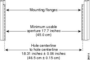
Before you install the chassis, measure the space between the vertical mounting flanges (rails) on your equipment rack to verify that the rack conforms to the measurements shown in the following figure.
Procedure
| 1. | Mark and measure the distance between two holes on the left and right mounting rails. The distance should measure 18.31 inches ± 0.06 inches (46.5 cm ± 0.15 cm).
|
|
| 2. | Measure the space between the inner edges of the left front and right front mounting flanges on the equipment rack. The space must be at least 17.7 inches (45 cm) to accommodate the chassis that is 17.25 inches (43.8 cm) wide and fits between the mounting posts on the rack. |
Attach the front rack-mount brackets
Before you begin
Before installing the chassis in the rack, you must install the rack-mount brackets on each side of the chassis.
Determine where in the rack you want the chassis to be mounted. If you are mounting more than one chassis in the rack, then start from the bottom up or the center of the rack. The following figure shows the brackets attached to the chassis. Depending on the bracket holes you use, the chassis may protrude in the rack.
The cable-management brackets are attached to the chassis after you install the chassis rack-mount brackets on the chassis and mount the chassis in the rack.
Procedure
| 1. | Locate the threaded holes on the side of the chassis. Ensure that you hold the front rack-mount bracket with the ear and holes facing outward and towards the front of the chassis. The following figures show where to attach the front rack-mount brackets to the Cisco 8500 Series Secure Routers. 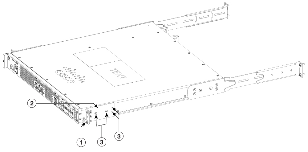
|
|
| 2. | Position the front rack-mount bracket top hole with the chassis, first top hole behind the side vent holes. |
|
| 3. | Insert and tighten the black screws on one side. |
|
| 4. | Repeat Step 1 through Step 3 on the other side of the chassis. Use screws to secure the rack-mount brackets to the chassis. Note, use the screw specified in the Bill of Materials (BOM). |
Attach the rear rack-mount brackets
Before you begin
This procedure is not required if you are installing the chassis in a two-post rack.
Before installing the chassis in a four-post rack, you must install the rear rack-mount brackets on each side of the chassis.
Determine where in the rack you want the chassis to be mounted. If you are mounting more than one chassis in the rack, then start from the bottom up or the center of the rack. The following figure shows the brackets attached to the chassis.
Procedure
| 1. | Locate the threaded holes on the side of the chassis. Ensure that you hold the rear rack-mount bracket with the ear and holes facing outward and towards the rear of the chassis. The following figures show where to attach the rear rack-mount brackets to the Cisco 500 Series Secure Routers 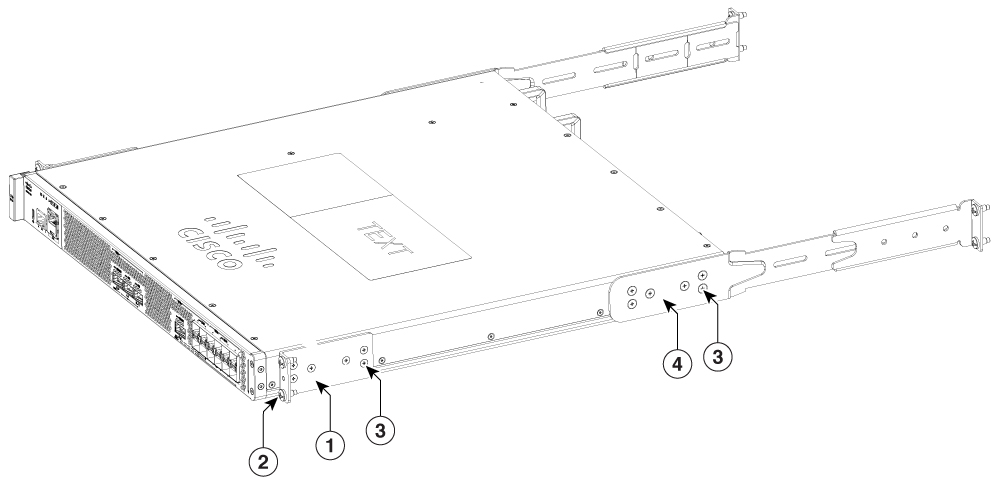
|
|
| 2. | Position the rear rack-mount bracket with the chassis. |
|
| 3. | Insert the black screws on one side. Do not fully tighten the screws. The rear bracket holes are slotted to allow for adjustment. Do not fully tighten the screws until the chassis is installed in the four-post rack. |
|
| 4. | Repeat Step 1 through Step 3 on the other side of the chassis. Use black screws to secure the rack-mount brackets to the chassis. |
Mount the router in the rack
After installing the rack-mount brackets on the chassis, mount the chassis by securing the rack-mount brackets to two posts or mounting strips in the rack using the screws provided. Because the rack-mount brackets support the weight of the entire chassis, ensure that you use all the screws to fasten the two rack-mount brackets to the rack posts.
Two-post rack installation
Statement 1006—Chassis Warning for Rack-Mounting and Servicing
To prevent bodily injury when mounting or servicing this unit in a rack, you must take special precautions to ensure that the system remains stable. The following guidelines are provided to ensure your safety:
This unit should be mounted at the bottom of the rack if it is the only unit in the rack.
When mounting this unit in a partially filled rack, load the rack from the bottom to the top with the heaviest component at the bottom of the rack.
If the rack is provided with stabilizing devices, install the stabilizers before mounting or servicing the unit in the rack.
The Cisco 8500 Series Secure Routers can be installed on a two-post rack, either 19 inch or 23 inch. We recommend that you allow at least 1 or 2 inches (2.54 or 5.08 cm) of vertical clearance between the router and any equipment directly above and below it.
Procedure
| 1. | On the chassis, ensure that all the screw fasteners on the installed components are securely tightened. |
|||||
| 2. | Make sure that your path to the rack is unobstructed. If the rack is on wheels, ensure that the brakes are engaged or that the rack is otherwise stabilized. |
|||||
| 3. | (Optional) Install a shelf in the rack to support the Cisco 8500 Series Secure Routers . If you use a shelf, it helps support the chassis while you secure it to the rack.
|
|||||
| 4. | With two people, lift the chassis into position between the rack posts. |
|||||
| 5. | Align the mounting bracket holes with the rack post holes and attach the chassis to the rack. |
|||||
| 6. | Position the chassis until the rack-mounting flanges are flush against the mounting rails on the rack.
|
|||||
| 7. | Hold the chassis in position against the mounting rails in the equipment rack and follow these steps: |
|||||
| 8. | Tighten all the screws on each side to secure the chassis to the equipment rack. The following figures show the Cisco 8500 Series Secure Routers on a two-post equipment rack. 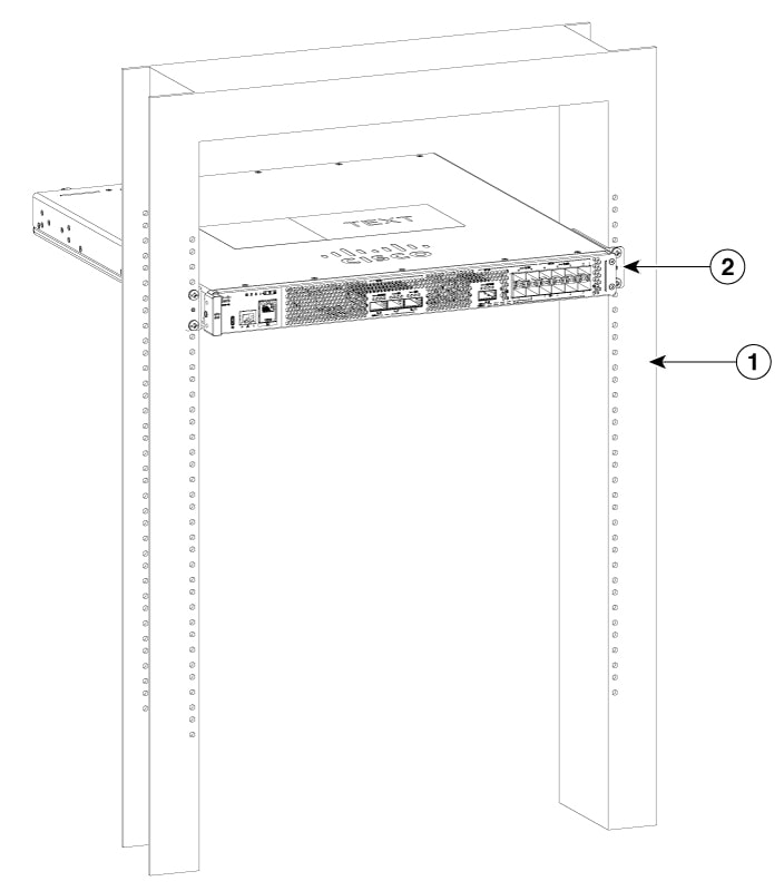
|
Four-post rack installation
Procedure
| 1. | (Optional) Install a shelf in the rack to support Cisco 8500 Series Secure Routers . If you use a shelf, it helps support the chassis while you secure it to the rack.
|
|||||||||
| 2. | With two people, lift the chassis into position between the rack posts. |
|||||||||
| 3. | Position the chassis until the rack-mounting flanges are flush against the mounting rails on the rack.
|
|||||||||
| 4. | Hold the chassis in position against the mounting rails while the second person finger-tightens a screw to the rack rails on each side of the chassis. |
|||||||||
| 5. | Finger-tighten screws to the rack rails on each side of the chassis. |
|||||||||
| 6. | Tighten all the screws on each side to secure the chassis to the equipment rack. 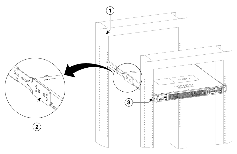
|
|||||||||
| 7. | Use a level to verify that the tops of the two brackets are level, or use a measuring tape to verify that both brackets are the same distance from the top of the rack rails. |
Attach the cable management bracket
The cable management brackets should be mounted to each rack-mount bracket on the chassis to provide cable management to both sides of the chassis (parallel with card orientation). These brackets are screw-mounted to the rack-mount brackets to allow easy installation and removal of cables.
The cable-management brackets for the Cisco 8500 Series Secure Routers contain one independent cable-management U-type feature with two screws for each bracket.
Make certain that the cable-management bracket "U" feature is facing upwards when you attach it to the Cisco 8500 Series Secure Routers .
Procedure
| 1. | Align the cable-management bracket to the rack-mount bracket on one side of the Cisco 8500 Series Secure Routers. The cable-management bracket aligns to the top hole of the chassis rack-mount bracket. |
|||||
| 2. | Using a Phillips screwdriver, insert one screw through the top screw hole of the cable-management bracket and into the chassis rack-mount bracket and tighten the screw.
The following figure show where to attach the cable-management brackets to the Cisco 8500 Series Secure Routers. 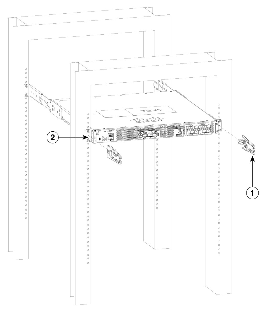
|
|||||
| 3. | Insert a screw through the hole in the cable management bracket and tighten using a Phillips screwdriver. |
|||||
| 4. | Repeat Step 1 through Step 3 for the other side of the chassis. |