Describes the physical chassis layouts of both Cisco C8570-G2 and C8550-G2 models, outlining front and rear panel views to help identify ports, bays, and key hardware components.
Cisco C8570-G2 chassis views
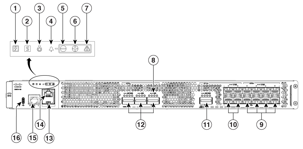
| 1 |
Power LED |
10 |
Bay 1 : 4x1/10 GE |
| 2 |
Status LED |
11 |
Bay 1 : Configurable 100G or 40G |
| 3 |
Beacon LED |
12 |
Bay 2 : Configurable 1x100G or 3x40G |
| 4 |
Main Alarm LED |
13 |
Micro USB Console Port |
| 5, 6 and 7 |
Minor, Major, Critical Alarm LEDs |
14 |
RJ 45 Console Port |
| 8 |
Link Status LED |
15 |
Management Port (RJ 45) |
| 9 |
Bay 0 : 8x 1/10 GE |
16 |
USB-C |
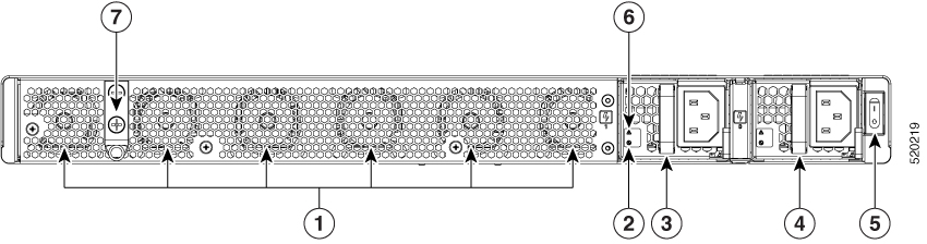
| 1 |
Fans |
5 |
Power switch |
| 2 |
Power supply AC input LED |
6 |
Power supply failure LED |
| 3, and 4 |
PEM 0, PEM 1 |
7 |
Ground Lug Attachment |
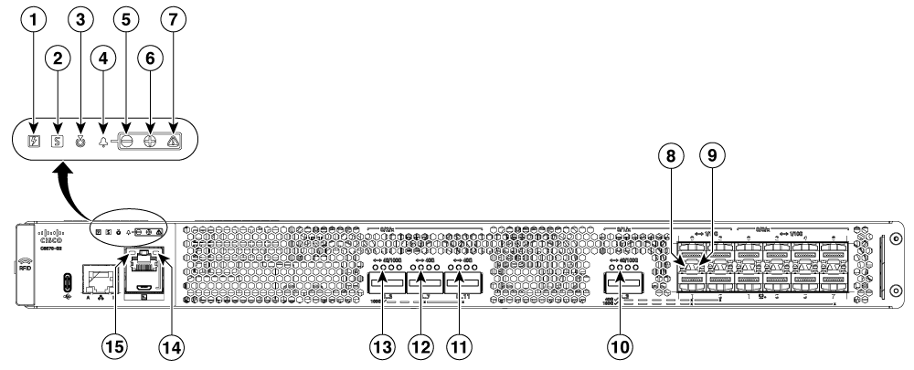
| 1 |
Power LED Off : No power to chassis. Yellow : Power On, one power supply has failed or is not plugged in. Green : All power is within specifications |
8,9 |
Top and Bottom Port LED |
| 2 |
Status LED Off : System not booted Red : System Failure Yellow : System booted to Rommon Green : System Booted to IOS |
10 |
Bottom Port LED |
| 3 |
Beacon LED |
11, 12 and 13 |
Link Status LED |
| 4 |
Alarm LED - Main |
14 |
USB Console Active LED Left LED On indicates that USB console is active |
| 5, 6 and 7, |
Alarm LED – Minor, Major and Critical |
15 |
Console RJ-45 Active LED Right LED On indicates that RJ-45 console is active |
Cisco C8550-G2 chassis views
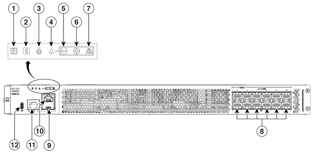
| 1 |
Power LED |
8 |
Bay 0 : 12x 1/10GE SFP+ ports |
| 2 |
Status LED |
9 |
Micro USB Control Port |
| 3 |
Beacon LED |
10 |
RJ 45 Console Port |
| 4 |
Alarm LEDs - Main |
11 |
Management Port RJ 45 |
| 5, 6 and 7 |
Minor, Major, Critical Alarm LEDs |
12 |
USB-C Micro-USB Console |
The following figure shows the rear view of C8550-G2
| 1 |
Fans |
5 |
Power Switch |
| 2 |
Power supply AC input LED |
6 |
Power supply failure LED |
| 3, and 4 |
PEM 0, PEM 1 |
7 |
Ground Lug Attachment |