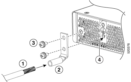
Explains chassis grounding procedures, recommending necessary tools and supplies, and providing instructions to securely attach a ground connection for safety and compliance.
Connecting the Cisco 8500 Series Secure Routers chassis to ground is required for all DC powered installations and any AC powered installation where compliance with Telcordia grounding requirements is necessary.
Statement 1024—Ground Conductor
This equipment must be grounded. To reduce the risk of electric shock, never defeat the ground conductor or operate the equipment in the absence of a suitably installed ground conductor. Contact the appropriate electrical inspection authority or an electrician if you are uncertain that suitable grounding is available.
Before you connect power or turn on power to your chassis, you must provide an adequate chassis ground (earth) connection for the chassis. A chassis ground connector is provided on Cisco 8500 Series Secure Routers. There is a stud on the rear left side of the chassis.
When customer properly install the chassis in a grounded rack, the switch is grounded because it has a metal-to-metal connection to the rack. Alternatively, customer can ground the chassis by using a customer-supplied grounding cable that meets your local and national installation requirements.
For U.S. installations, 6-AWG wire is recommended. Connect the grounding cable to the chassis with a grounding lug and to the facility ground.
The grounding wire should always be the first to be installed or connected and the last to be removed or disconnected.
An electrical conducting path shall exist between the product chassis and the metal surface of the enclosure or rack in which it is mounted, or to a grounding conductor. Electrical continuity shall be provided by using thread-forming type mounting screws that remove any paint or non-conductive coatings, and establish a metal-to-metal contact. Any paint or non-conductive coatings shall be removed on the surfaces between the mounting hardware and the enclosure or rack. The surfaces shall be cleaned and an antioxidant applied before installation.
Have the recommended tools and supplies available before you begin this procedure.