Explains power supply options for the Cisco 8500 Series Secure Routers, including AC and DC power supply modules, LED indicators, and integrated fans to ensure operational reliability and status monitoring.
AC power supply
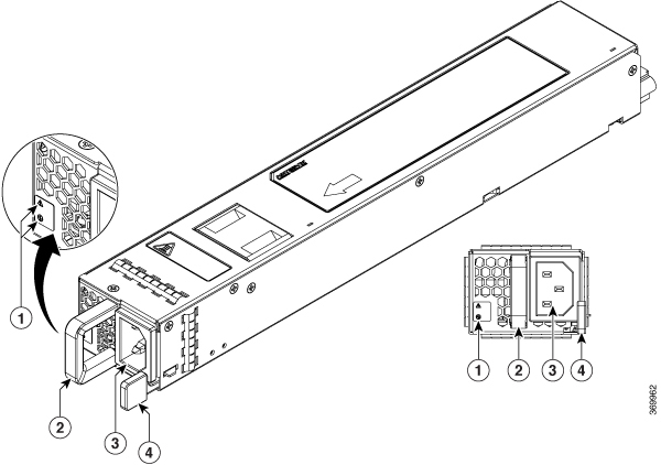
| 1 |
Fail and OK LEDs |
3 |
AC power connector |
| 2 |
Handle |
4 |
Retaining latch |
DC power supply
The DC (PWR-CH1-950WDCR) input connector is a two-wire connector with connection polarity from left to right (when facing the unit) of positive (+) and negative (–).
The power supply has a handle to be used for insertion and extraction. The module must be supported with one hand because of its length.
The airflow direction is front to back with ambient air drawn in from the venting located on the chassis front sides.
The following figure shows the DC power supply.
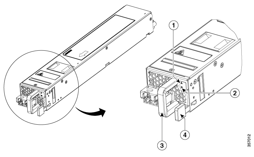
| 1 |
Fail LED |
2 |
OK LED |
| 3 |
Handle |
4 |
Retaining latch |
Power supply LED
The following table describes the power supply LED.
| Power Supply Condition |
Green (OK) LED Status |
Amber (FAIL) LED Status |
|---|---|---|
| No power to all power supplies |
Off |
Off |
| Power Supply Failure (includes over voltage, over current, over temperature and fan failure) |
Off |
On |
| Power Supply Warning events where the power supply continues to operate (high temperature, high power and slow fan) |
Off |
1Hz (blinking once per second) |
| AC Present/3.3VSB on (PSU Off) |
1Hz (blinking once per second) |
Off |
| Power Supply On and OK |
On |
Off |
Power supply fans
The fans in the power supply module are used for cooling the power supply module itself while system-level cooling is provided by fans within the chassis. The power supplies do not depend on the system-level fans for cooling. Fan failure is determined by fan-rotation sensors.
The chassis has a front-to-rear airflow. All of the power supplies and fan modules in the same chassis must use the same airflow direction or an error will occur with possible overheating and shut down of the router. If you power up the router with more than one airflow direction, you must power down the router and replace the modules with the wrong airflow direction before powering up the router.
The fans in the power supply modules will run as soon as the power supply is plugged in, even if the power switch is in the Standby position.