Details installation and removal of DC power supplies, covering the wiring of DC input power sources and safe disconnection and replacement to maintain uninterrupted device operation.
Installing DC input power supplies
Statement 1003—Power Disconnection
To reduce risk of electric shock, before performing any of the following procedures, ensure that power is removed from the system.
Do not install the power supplies with the chassis cover off.
This section describes how to install the DC power supply input power leads to the DC input power supply. Before you begin, read these important notices:
-
The color coding of the DC input power supply leads depends on the color coding of the DC power source at your site. Ensure that the lead color coding you choose for the DC input power supply matches the lead color coding used at the DC power source and verify that the power source is connected to the negative (–) terminal and to the positive (+) terminal on the power supply.
-
Ensure that the chassis ground is connected on the chassis before you begin installing the DC power supply. Follow the steps provided in the Chassis Ground Connection section.
-
For DC input power cables, the wire gauge is based on the National Electrical Code (NEC) and local codes for 26 amp service at nominal DC input voltage (–40/–72 VDC). One pair of cable leads, source DC (–) and source DC return (+), are required for each power distribution unit (PDU). These cables are available from any commercial cable vendor. All DC input power cables for the chassis should be 10 gauge wire and cable lengths should match within 10 percent of deviation.
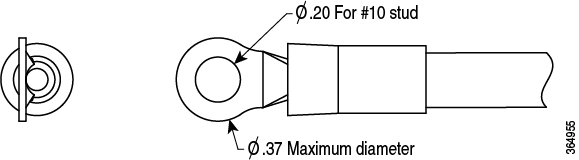
Each DC input power cable is terminated at the PDU by a cable lug, as shown in the following figure.
DC input power cables must be connected to the PDU terminal studs in the proper positive (+) and negative (–) polarity. In some cases, the DC cable leads are labeled, which is a relatively safe indication of the polarity. However, you must verify the polarity by measuring the voltage between the DC cable leads. When making the measurement, the positive (+) lead and the negative (–) lead must always match the (+) and (–) labels on the power distribution unit.
To avoid hazardous conditions, all exposed conductors must be covered. If after placing the protective cover over the DC terminal block, conductors are exposed, these should be insulated to prevent accidental contact.
Wire the DC input power source
Statement 1046—Installing or Replacing the Unit
To reduce risk of electric shock, when installing or replacing the unit, the ground connection must always be made first and disconnected last.
Procedure
| 1. | Turn off the circuit breaker from the power source. |
|
| 2. | Ensure that the chassis power switch is in the Standby position.
|
|
| 3. | Use a wire-stripping tool to remove approximately 0.75 inch (19 mm) of the covering from the end of the wire. The wire should be stripped so that it extends into the barrel of the lug without extending out of it. Additionally, the insulation should not be inside the barrel. 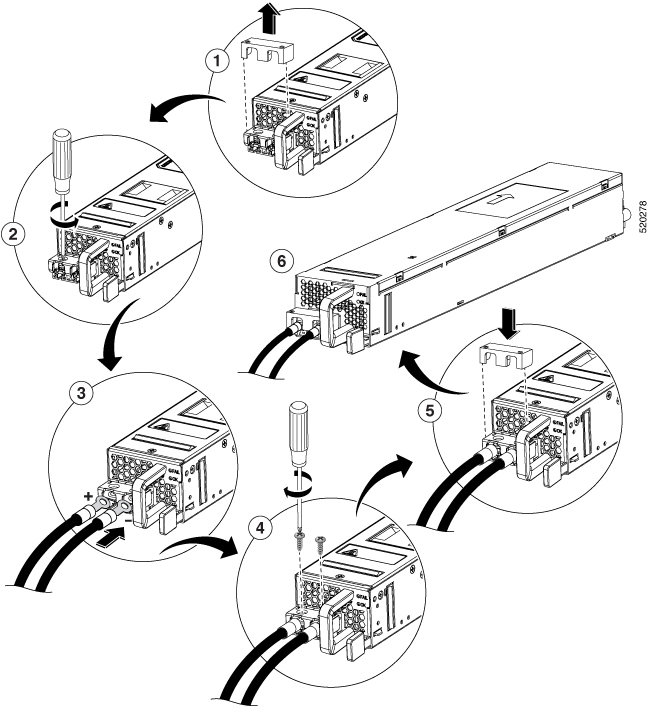
|
|
| 4. | Insert the stripped end of the wire into the open end of the lug. |
|
| 5. | Crimp the wire in the barrel of the lug. Verify that the wire is securely attached to the lug. |
|
| 6. | Place the wire against the terminal block, making sure there is solid metal to metal contact. |
|
| 7. | Secure the lugs to the chassis with two M4 screws. Ensure that the lug and the wire will not interfere with other switch hardware or rack equipment. |
|
| 8. | Replace the snap on cover on the terminal block of the DC power supply. |
Remove DC power supplies
The DC power supply has a terminal block that is installed into the power supply terminal block header.
Procedure
| 1. | Turn off the circuit breaker from the power source. |
|
| 2. | Ensure that the chassis power switch is in the Standby position.
|
|
| 3. | Remove the plastic cover from the terminal block. |
|
| 4. | Unscrew the two terminal block screws on the unit and remove the wires from the power supply. |
|
| 5. | Press the power supply retaining latch towards the pull handle, grasp the handle with one hand, and pull the power supply out of the slot while supporting the weight of the power supply with the other hand. |