Cisco 8500 Series Secure Routers Hardware Installation Guide

PDF

Cisco 8500 Series Secure Routers Hardware Installation Guide

Remove and replace a DIMM

Want to summarize with AI?

Log in

Describes steps for removing and replacing a DIMM, including specific procedures for safe extraction and installation to maintain memory integrity in hardware systems.


The Cisco 8500 Series Secure Router has two DIMM slots and supports 16-GB configuration by default.

Table 1. Supported Slots for Inserting the DIMMs

Memory PID Option

Memory Channel B

Slot 0 (U1DA0) Slot 2 (U1DB0)

MEM-C85G2-32GB

16 GB

16 GB

MEM-C85G2-64GB

32 GB

32 GB


Remove a DIMM

Before you begin

Perform the following steps before you begin the process of removing and replacing a DIMM from a Cisco 8500 Series Secure Router:

  • Use an ESD-preventive wrist strap.

  • Back up the data that you want to save.

  • Remove the power supplies before you remove the chassis top cover.

Procedure

1.

With an ESD wrist strap on, remove the power supplies from the chassis.

2.

Remove the chassis top cover by performing the following steps:

  1. Remove the nine Torx screws on the top surface of the cover, along with the five Torx screws on each side of the cover, using a Torx T8 driver. Then, remove the remaining three screws on the top surface of the cover with a small Phillips screwdriver.

  2. After removing the screws, lift off the chassis cover.

3.

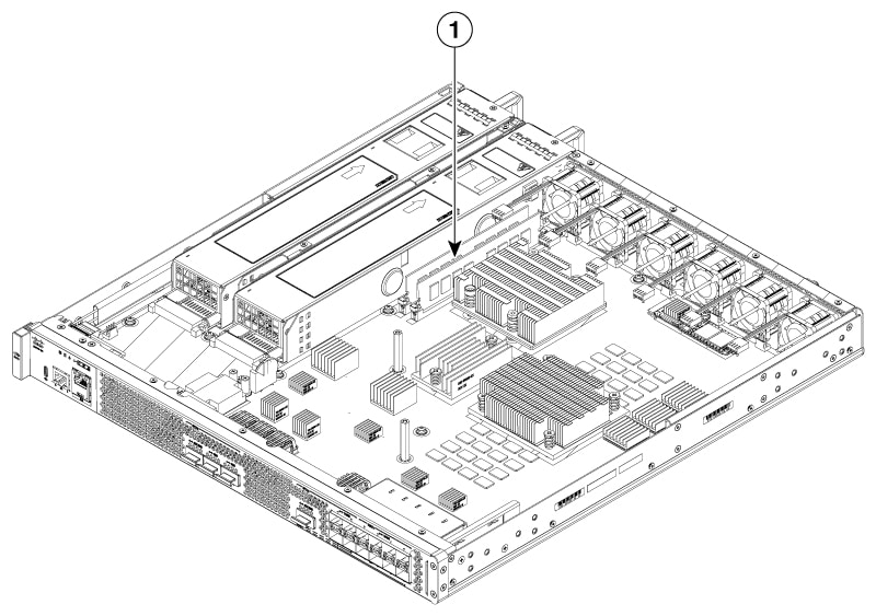
Locate the DIMMs on the router.

Figure 1. DIMM Location in Cisco 8500 Series Secure Router

1

Cisco 8500 Series Secure Router DIMM location slot

4.

Pull down the DIMM module spring latches to release the corresponding DIMM from the socket.

5.

When both ends of the DIMM are released from the socket, grasp each end of the DIMM with your thumb and forefinger and pull the DIMM completely out of the socket. Handle only the edges of the DIMM; avoid touching the memory module, pins, and the metal traces (the metal fingers along the connector edge of the DIMM) along the socket edge.

6.

Place the DIMM in an antistatic bag to protect it from ESD damage.


Replace a DIMM

Procedure

1.

Place the DIMM on an antistatic mat or pad while wearing an antistatic device, such as a wrist strap.

Caution

DIMMs are sensitive components that can be shorted by mishandling; they are susceptible to ESD damage. Handle the DIMM by the edges only, and avoid touching the pins.

2.

Remove the new DIMM from the antistatic bag.

3.

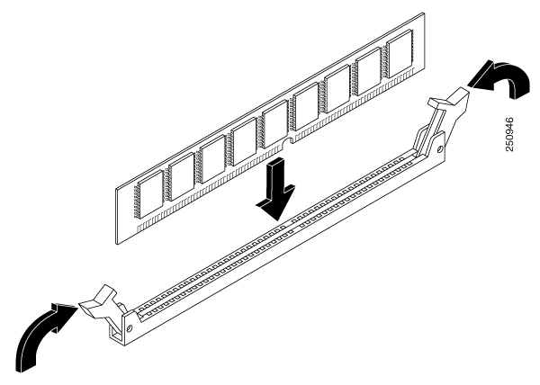
Locate the keying notch and align the DIMM with the socket before inserting it.

4.

Gently insert the new DIMM, taking care not to damage the pins on the edge of the DIMM. Press the top of the DIMM towards the socket, being careful to apply force only on the DIMM that is parallel with the plane of the DIMM.

Caution

When inserting DIMMs, use firm but not excessive pressure. If you damage a socket, you will have to return the router to the factory for repair.

Figure 2. Installing a DIMM in the Socket
5.

After the DIMM is installed, check whether the release levers are flush against the sides of the DIMM socket. If they are not, the DIMM might not be seated properly. If the DIMM appears misaligned, carefully remove it according to the removal procedure and then reseat it in the socket. Push the DIMM firmly back into the socket until the release levers are flush against the sides of the DIMM socket.

6.

Replace the chassis top cover. Install the top surface screws, side screws and tighten them slightly

7.

Install the power supplies into the chassis and power up the router.