Configuration Guide for Cisco NCS 1004, IOS XR Release 25.x.x

PDF

Configuration Guide for Cisco NCS 1004, IOS XR Release 25.x.x

Automatic protection switching on OTN-XP card

Want to summarize with AI?

Log in

This section explains how automatic protection switches (APS) operate on trunk ports of NCS1K4-OTN-XP cards in the NCS 1004 platform.


Automatic Protection Switching (APS) is a feature that

  • provides protection against optical fiber faults or signal failure on trunk ports of NCS1K4-OTN-XP cards,

  • automatically switches traffic to the protection path when a signal failure is detected on the working path, and

  • supports both automatic and manual protection switching on supported trunk ports.

Feature history

Table 1. Feature history

Feature Name

Release Information

Description

APS Support for 100G and 200G Trunk Bandwidth on OTN XP Cards

Cisco IOS XR Release 7.9.1

In addition to the 400G trunk bandwidth, you can now configure Automatic Protection Switching (APS) for the following trunk bandwidth combinations:

  • 200G DWDM with 2x100G clients

  • 100G QSFP28 Grey and 10x10G clients

Automatic Protection Switching (APS) on OTN XP Card

Cisco IOS XR Release 7.8.1

APS provides protection mechanism against optical fiber faults or signal failure. In case a failure is detected, live traffic is automatically moved from the working path to the protection path to prevent any data loss. Following trunk bandwidth combinations are supported:

  • 400G DWDM with 4x100G clients

  • 400G DWDM with 400G clients

You can enable this feature using the protected keyword of the hw-module command.

Pluggable switching times and port mapping

APS allows you to configure protection switching on trunk ports of NCS1K4-OTN-XP Cards. Protection switching automatically switches traffic from one path to another working path if any signal failure occurs. This requires configuring working and protection paths on trunk ports where the protection path works as backup for the working path. Usually, the working path is the active path and carries traffic. The traffic immediately switches to the protection path if a signal failure occurs on the working path.

This figure explains the working of APS where the traffic is immediately switched from working path to the protection path in case of a signal failure.
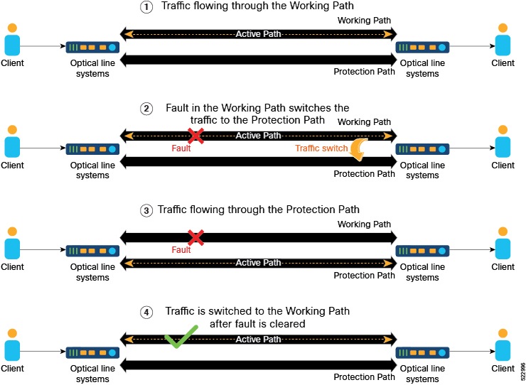
Figure 1. Automatic Protection Switching

If an electrical(TP1) or optical(TP3) signal is interrupted or disturbed at the client pluggable and the CDR inside the QDD loses the Rx lock, then the QDD pluggable requires 1.5 to 2 seconds to recover from the Rx loss.

You can employ both the GL-1 and GL-2 pluggable trunk protection features. The GL-2 pluggable supports both Flexcoh and Termination modes. The GL-2 Termination mode offers a shorter switching time compared to the Flexcoh mode, and supports both GL-2 and GL-1 pluggables.

The Pluggables Switching Time table lists the 100G and 400G client pluggables that either support or do not support switching from the active path to the protection path within 50 milliseconds.

Table 2. Pluggables switching time

Pluggables Supporting Switching within 50 ms

Pluggables not Supporting Switching within 50 ms

100G

400G

100GE

400GE

ONS-QSFP28-LR4

-

QSFP-100G-FR-S

QDD-400G-DR4-S

QSFP-100G-LR-S

-

-

QDD-400G-FR4-S

QSFP-100G-SR4-S

-

-

-

QSFP-100G-DR-S

-

-

-

QSFP-100G-CWDM4-S

-

-

-

Note

According to the QDD pluggable standard, if an electrical (TP1) or optical (TP3) signal is interrupted or disturbed at a client pluggable, and the Clock and Data Recovery (CDR) inside the QDD loses the lock, the QDD pluggable requires some time to recover the signal. Hence, when a fault is identified on the trunk port, the client port Rx loses the lock. The recovery takes between 1.5 to 2 s depending on the pluggable standard.


Enable APS on trunk

Enable APS on trunk ports to provide protection for DWDM and 10G-Grey-MXP client connections and configure the required bandwidth settings.

Before configuring APS, it must be enabled on the trunk ports of the NCS1K4-OTN-XP cards. Trunk protection on the NCS1K4-OTN-XP card supports 400G, 200G, and 100G bandwidth.

Follow these steps to configure APS on trunk ports:

Procedure

1.

Run these commands to enable protection switching and configure the client and trunk bandwidth for DWDM.

  • hw-module locationlocation mxponderprotected trunk-ratetrunk rate client-port-rate[0 | 4 | 5 | 8] client-type [100GE | 400GE] to enable protection switching and configure the client and trunk bandwidth for DWDM.
  • hw-module locationlocation mxponderprotected trunk-ratetrunk rate client-port-rate [4 | 5 | 2 | 8] lane lane number client-type [ 10GE | otu2 | otu2e] command to enable protection switching and configure the client and trunk bandwidth for 10G-Grey-MXP.

    For more information about these commands, see Command Reference for Cisco NCS 1004.

Example:

This example shows how to configure protection datapath on slot 0 of the NCS1K4-OTN-XP card. This example also shows how you can configure client port at 400GE to achieve a total bandwidth of 400G at the trunk port.

RP/0/RP0/CPU0:ios(config)#hw-module location 0/0
RP/0/RP0/CPU0:ios(config-hwmod)# mxponder
RP/0/RP0/CPU0:ios(config-hwmod-mxp)#  protected
RP/0/RP0/CPU0:ios(config-hwmod-mxp)#  trunk-rate 400G
RP/0/RP0/CPU0:ios(config-hwmod-mxp)#  client-port-rate 8 client-type 400GE
RP/0/RP0/CPU0:ios(config-hwmod-mxp)#commit

This example shows how to configure protection datapath on slot 2 of the NCS1K4-OTN-XP card. This example also shows how you can configure client ports 0, 4, 5 and 8 with a bandwidth of 100GE each to achieve a total bandwidth of 400G at the trunk port.


RP/0/RP0/CPU0:ios(config)#hw-module location 0/2
RP/0/RP0/CPU0:ios(config-hwmod)#mxponder
RP/0/RP0/CPU0:ios(config-hwmod-mxp)#protected
RP/0/RP0/CPU0:ios(config-hwmod-mxp)#trunk-rate 400G
RP/0/RP0/CPU0:ios(config-hwmod-mxp)#client-port-rate 0 client-type 100GE
RP/0/RP0/CPU0:ios(config-hwmod-mxp)#client-port-rate 4 client-type 100GE
RP/0/RP0/CPU0:ios(config-hwmod-mxp)#client-port-rate 5 client-type 100GE
RP/0/RP0/CPU0:ios(config-hwmod-mxp)#client-port-rate 8 client-type 100GE
RP/0/RP0/CPU0:ios(config-hwmod-mxp)#commit

Example:

This example shows how to configure protection datapath on slot 2 of the NCS1K4-OTN-XP card. This example also shows how you can configure client ports 5 and 8 with a bandwidth of 100GE or otu4 each to achieve a total bandwidth of 200G at the trunk port.


RP/0/RP0/CPU0:ios(config)#hw-module location 0/2
RP/0/RP0/CPU0:ios(config-hwmod)#mxponder
RP/0/RP0/CPU0:ios(config-hwmod-mxp)#protected
RP/0/RP0/CPU0:ios(config-hwmod-mxp)#trunk-rate 200G
RP/0/RP0/CPU0:ios(config-hwmod-mxp)#client-port-rate 5 client-type 100GE
RP/0/RP0/CPU0:ios(config-hwmod-mxp)#client-port-rate 8 client-type otu4
RP/0/RP0/CPU0:ios(config-hwmod-mxp)#commit

This example shows how to configure protection datapath on slot 2 of the NCS1K4-OTN-XP card. This example also shows how you can configure client port 2 of lane 3 and lane 4. This examples also shows how to configure client port 4 and 5 of lane 1, lane 2, lane 3, and lane 4 with a bandwidth of 10GE each to achieve a total bandwidth of 100G at the trunk port.


RP/0/RP0/CPU0:ios(config)#hw-module location 0/2
RP/0/RP0/CPU0:ios(config-hwmod)#mxponder
RP/0/RP0/CPU0:ios(config-hwmod-mxp)#protected
RP/0/RP0/CPU0:ios(config-hwmod-mxp)#trunk-rate 100G
RP/0/RP0/CPU0:ios(config-hwmod-mxp)#client-port-rate 4 lane 1 client-type 10GE
RP/0/RP0/CPU0:ios(config-hwmod-mxp)#client-port-rate 4 lane 2 client-type 10GE
RP/0/RP0/CPU0:ios(config-hwmod-mxp)#client-port-rate 4 lane 3 client-type 10GE
RP/0/RP0/CPU0:ios(config-hwmod-mxp)#client-port-rate 4 lane 4 client-type 10GE
RP/0/RP0/CPU0:ios(config-hwmod-mxp)#client-port-rate 5 lane 1 client-type 10GE
RP/0/RP0/CPU0:ios(config-hwmod-mxp)#client-port-rate 5 lane 2 client-type 10GE
RP/0/RP0/CPU0:ios(config-hwmod-mxp)#client-port-rate 5 lane 3 client-type 10GE
RP/0/RP0/CPU0:ios(config-hwmod-mxp)#client-port-rate 5 lane 4 client-type 10GE
RP/0/RP0/CPU0:ios(config-hwmod-mxp)#client-port-rate 2 lane 3 client-type 10GE
RP/0/RP0/CPU0:ios(config-hwmod-mxp)#client-port-rate 2 lane 4 client-type 10GE
RP/0/RP0/CPU0:ios(config-hwmod-mxp)#commit

This example shows how to configure protection datapath on slot 2 of the NCS1K4-OTN-XP card. This example shows how you can configure different client ports with mixed bandwidth on different lanes.


RP/0/RP0/CPU0:ios(config)#hw-module location 0/2
RP/0/RP0/CPU0:ios(config-hwmod)#mxponder
RP/0/RP0/CPU0:ios(config-hwmod-mxp)#protected
RP/0/RP0/CPU0:ios(config-hwmod-mxp)#trunk-rate 100G
RP/0/RP0/CPU0:ios(config-hwmod-mxp)#client-port-rate 4 lane 1 client-type 10GE
RP/0/RP0/CPU0:ios(config-hwmod-mxp)#client-port-rate 4 lane 2 client-type OTU2
RP/0/RP0/CPU0:ios(config-hwmod-mxp)#client-port-rate 4 lane 3 client-type OTU2E
RP/0/RP0/CPU0:ios(config-hwmod-mxp)#client-port-rate 4 lane 4 client-type OTU2E
RP/0/RP0/CPU0:ios(config-hwmod-mxp)#client-port-rate 5 lane 1 client-type OTU2
RP/0/RP0/CPU0:ios(config-hwmod-mxp)#client-port-rate 5 lane 2 client-type 10GE
RP/0/RP0/CPU0:ios(config-hwmod-mxp)#client-port-rate 5 lane 3 client-type 10GE
RP/0/RP0/CPU0:ios(config-hwmod-mxp)#client-port-rate 5 lane 4 client-type OTU2
RP/0/RP0/CPU0:ios(config-hwmod-mxp)#client-port-rate 2 lane 3 client-type OTU2E
RP/0/RP0/CPU0:ios(config-hwmod-mxp)#client-port-rate 2 lane 4 client-type 10GE
RP/0/RP0/CPU0:ios(config-hwmod-mxp)#commit
2.

Run the commit command to save and apply the configuration changes.

APS is enabled on trunk ports and client/trunk bandwidth is configured according to requirements.


Configure APS ODU group controller

Set up an APS ODU group controller with optimal protection modes and verify the configuration.
This table displays the port mapping that can be used to map client and trunk port bandwidth.
Table 3. Client and trunk port mapping for NCS1K4-OTN-XP cards

Trunk bandwidth

Trunk ports

Client bandwidth

Client ports (Slice 1)

400G

12, 13

400GE

8

400G

12, 13

4x100G

0, 4, 5 and 8

200G

12, 13

2x100G

5 and 8

100G

0, 1

10x10G

  • Client Port 4 - Lanes 1, 2, 3, and 4

  • Client Port 5 - Lanes 1, 2, 3, and 4

  • Client Port 2 - Lanes 3 and 4

Before you begin

Define the working and protecting resources in an ODU group controller. Before configuring the protection attributes, you must create an ODU group controller and configure the ports 12 or 13 as the working and/or protection paths.

Procedure

1.

Run these commands.

  • controller odu-group-mp Group-ID signalclient-signal-type odu-type type-of-the-oduprotecting-controller [ODUk Rack/Slot/Instance/Port] working-controller [ODUk Rack/Slot/Instance/Port] to first create an ODU group controller and define the working and protection paths inside the group.

Example:

This example shows how to create an ODU group MP 2 with ODU type ODUC4. This example also shows how to configure the port numbers 12 and 13 as working and protection paths respectively.


RP/0/RP0/CPU0:ios(config)# controller Odu-Group-Mp 2 signal Otn odu-type ODUC4
RP/0/RP0/CPU0:ios(config)# protecting-controller ODUC4 0/2/0/13
RP/0/RP0/CPU0:ios(config)# working-controller ODUC4 0/2/0/12
 
Note

If both APS and L1 Encryption are configured on the same ODU group controller, configure the GCC2 interface and the corresponding IP addresses for each trunk port separately. This ensures that any service impact on a trunk port does not affect the encryption functionality and also the independent working and protected paths for 1+1 trunk protection are maintained. For more details about configuring GCC interface, see Configuring the GCC Interface

  • protection-attributes protection-type [APSbidi]

    protection-attributes protection-mode [revertive wait-to-restore-time] timer

    protection-attributes connection mode [snc-n] to configure the recommended protection attributes of an ODU group controller.

    Note
    • hold-off-time is an optional parameter. If this parameter is not specified, the default parameter value is used.

    • The recommended parameters for configuring protection attributes of an ODU Group Controller are snc-n, APSbidi, and wait-to-restore-time.

Example:

This example shows how to configure protection attributes protection type, protection mode, connection mode, and timers on the ODU group MP 2.


 RP/0/RP0/CPU0:ios(config)# protection-attributes timers hold-off-time 1000
 RP/0/RP0/CPU0:ios(config)# protection-attributes protection-type APSbidi
 RP/0/RP0/CPU0:ios(config)# protection-attributes protection-mode revertive wait-to-restore-time 400
 RP/0/RP0/CPU0:ios(config)# protection-attributes connection-mode snc-n

For more information about these commands, see Command Reference for Cisco NCS 1004.

2.

Run these commands to verify the configuation.

  • show controllers odu-group-mp Group-ID to verify the APS configuration details on ODU group controller such as, ODU group name, working path, protection path, and protection parameters.

    This example shows how to verify the APS configuration details of the ODU group MP 2.

    
    RP/0/RP0/CPU0:ios# show controllers odu-group-mp 2
    ODU  Group Information
    --------------------------------------------------------------
    ODU GROUP ID                                    :  2
    Controller State                                :  Up
     WORKING CONTROLLER
    ODU NAME                                        :  ODUC4 0/0/0/12
    ODU ROLE                                        :  WORKING
    ODU STATE                                       :  Active_tx
    Local Failure                                   :  Yes
    Remote Failure                                  :  Yes
    PROTECTED CONTROLLER
    ODU NAME                                        :  ODUC4 0/0/0/13
    ODU ROLE                                        :  PROTECT
    ODU STATE                                       :  Active
    Local Failure                                   :  No
    Remote Failure                                  :  No
    PROTECTION PARAMETERS :
    Connection Mode                                 :  SNC_N
    Protection Type                                 :  1+1 Bidirectional Protection
    Tcmid                                           :  0
    Protection Mode                                 :  Revertive
    Hold off timer                                  :  1000
    Wait-to-restore timer                           :  400000 ms
    Detected Alarms                                 :  Switched To Protection
  • show controllers odu-group-mp Group-ID protection-detail to verify the hardware details of the ODU group controller.

Example:

This example shows how to view the ODU group controller 2 hardware details.


RP/0/RP0/CPU0:ios#show  controllers odu-group-mp 2 protection-detail
ODU  Group Information
--------------------------------------------------------------
LOCAL
                Request State                   : Signal Failed
                Request signal                  : 0
                Bridge signal                   : 1
                Bridge Status                   : 1+1
REMOTE
                Request State                   : Signal Failed
                Request signal                  : 0
                Bridge signal                   : 1
                Bridge Status                   : 1+1
WORKING
                Controller Name                 : ODUC40_0_0_12
                ODU STATE                       : Active_tx
                Local Failure                   : Signal Failure
                Remote Failure                  : Signal Failure
                WTR Left                        : 0 ms
PROTECT
                Controller Name                 : ODUC40_0_0_13
                ODU STATE                       : Active
                Local Failure                   : State Ok
                Remote Failure                  : State Ok
                WTR Left                        : 0 ms
Client
                Controller Name                 : ODUC40_0_0_0
                ODU STATE                       : Not Present

Wait to restore                                 : 400000 ms
Hold-off-timer                                  : 1000 ms
Current State                                   : Signal failed on Working
Previous State                                  : No Request State

The ODU group controller is configured with working and protecting paths and protection attributes.


Perform APS manual switching

Enable manual control over protection switching, allowing you to trigger lockout, manual, or forced switch operations for maintenance or fault scenarios.

Protection switching is usually triggered automatically when a signal failure is detected. However, you can trigger a switch manually as well using the protection switching commands. This table describes these switching commands and their priority levels that can be used to triggered a switch manually.

Table 4. Manual protection switching commands priority levels

Priority

Priority request

Description

1

lockout

Use this command to lockout the working path and prevent switching to the protection path. When lockout is configured, traffic is not switched to the protection path even if a failure is detected.

This command has the highest priority level and overrides all the other protection switching commands. This means that if lockout is configured, you cannot trigger force and manual commands.

2

force

Use this command to trigger a force-switch from the working path to the protection path and vice-versa.

This command cannot be triggered if lockout is configured.

3

manual

Use this to manually switch from the working path to the protection path or vice-versa in case a maintenance is scheduled on any of the paths.

This command cannot be triggered if lockout and force is configured.

If there is a signal failure on the protection path, you can prevent the switching of traffic from the working path to the protection path by locking out the working path. Lockout command has the highest priority and overrides all other switching commands.

Follow these steps to manually switch APS protection paths:

Procedure

Run these commands.

  • odu-group-mp Group-ID signal client-signal-type odu-type type-of-the-odu

    protection-switching operate lockout odu-dest [ODUk Rack/Slot/Instance/Port] to perform a lockout.

Example:

This example shows how to configure lockout on an ODUC4 on the working path 0/2/0/13.


RP/0/RP0/CPU0:ios(config)#Odu-Group-Mp2 signal Otn odu-type ODUC4
RP/0/RP0/CPU0:ios(config-Odu-Group-Mp2)#protection-switching operate lockout odu-dest ODUC4 0/2/0/13
RP/0/RP0/CPU0:ios(config-Odu-Group-Mp2)#commit

If there are changes to be done during a scheduled maintenance window on the working or protection paths, you can perform a manual switch from the working path to the protection path or the opposite way. This command is overridden by the force and lockout commands.

  • odu-group-mp Group-ID manual odu-dest ODUk Rack/Slot/Instance/Port to perform a manual switch.
    Note

    The manual switch command works irrespective of the working or protection path Rack/Slot/Instance/Port and uses only the Group-ID to switch the traffic.

    This example shows how to manually switch traffic.

    RP/0/RP0/CPU0: odu-group mp 1 manual odu-dest ODUC4 0/2/0/13
  • Run the odu-group-mp Group-ID forced odu-dest ODUk Rack/Slot/Instance/Port command to perform a forced switch of traffic from the working path to the protection path and also, conversely.
    Note

    The forced switch command works irrespective of the working or protection path Rack/Slot/Instance/Port and uses only the Group-ID to switch the traffic.

    This example shows how to force switch the traffic.

    RP/0/RP0/CPU0: odu-group mp 1 forced odu-dest ODUC4 0/2/0/13