Configuration Guide for Cisco NCS 1004, IOS XR Release 25.x.x

PDF

Configuration Guide for Cisco NCS 1004, IOS XR Release 25.x.x

Configuring OTNSec workflows on NCS1004

Want to summarize with AI?

Log in

Describes the workflow, key components, and process stages for configuring IKEv2 and OTNSec encryption on NCS1004 using CA-based and PSK-based authentication.


Configuring OTNSec on NCS1004 ensures secure data transmission by establishing IKEv2 and OTNSec encryption using either certificate authority (CA) or pre-shared key (PSK) authentication. The process involves preparing prerequisites, choosing an authentication method, and completing a series of configuration steps.

Summary

The key components involved in the process are:

  • NCS1004 device: The platform where OTNSec encryption is configured.

  • Authentication methods: Supports both certificate authority (CA) and pre-shared keys (PSK), providing flexibility for different security needs.

  • Required software and hardware preparation: The k9sec.rpm package must be installed and the line card configured in muxponder slice mode.

Workflow

The process involves the following stages:

  1. Complete prerequisites:
    • Install the required k9sec.rpm package
    • Configure the line card in slice mode. See .
  2. Configuring IKE:
    • Configure IKEv2 proposals for secure negotiation: (Optional) Configure an IKEv2 proposal manually;otherwise, the default IKEv2 proposal is used in the default IKEv2 policy. The default IKEv2 proposal requires no configuration and is a collection of commonly used transforms types, which are as follows:
      encryption cbc-aes-256
      integrity sha512, sha384
      prf sha512, sha384
      dh 19, 20, 21
    • Configure a keyring: Configure a keyring as the local or remote authentication method is a preshared key.
    • Configure an IKEv2 policy: (Optional) Configure an IKEv2 policy manually;otherwise, the default proposal associated with the default policy is used for negotiation. An IKEv2 policy with no proposal is considered incomplete.
    • Configure an IKEv2 profile: Configure an IKEv2 profile. The IKEv2 profile must be attached to the OTNSec profile on both the IKEv2 initiator and the responder. The DPD interval is 10 seconds. If there is no response from the peer node, it retries every two seconds with a maximum of five attempts. After five retries, the IKE session is brought down. NCS 1004 supports headless mode. Therefore, even though the control plane is down, traffic is not impacted because the encryption and decryption keys are still active on the line cards. The data path functions in a locally secure mode and the OTNSEC-LOCALLY-SECURED alarm is raised.
  3. Configure OTNSec:
  4. Verify the IKE and OTNSec encryption configuration: Commands for verifying IKEv2 and OTNSec configuration on Cisco NCS 1004

Result

Successfully configuring OTNSec and IKEv2 encryption on the NCS1004 device ensures secure transmission of data across optical networks. The process enables flexible authentication with either certificate authority (CA) or pre-shared key (PSK) methods, maintains robust protection even in headless mode, and raises relevant alarms for locally secured data paths, thereby safeguarding sensitive traffic against unauthorized access and disruption.

Configure IKEv2 proposals for secure negotiation

Set up an IKEv2 proposal with the required cryptographic algorithms to ensure secure negotiation of IKE SAs.

An IKEv2 proposal specifies a collection of transforms (encryption, integrity, pseudo-random function, Diffie-Hellman group) used in the IKE_SA_INIT exchange. Properly configuring proposals is critical to meeting your network’s security requirements. If you use an AES-GCM encryption algorithm, you do not need to configure an integrity algorithm. AES-GCM and non-GCM algorithms cannot be mixed in the same proposal, but you can attach different proposals to the same IKEv2 policy if needed.

Procedure

1.

Create the IKEv2 proposal and assign a name.

Example:

RP/0/RP0/CPU0:ios#configure
Thu Mar  7 19:19:30.259 UTC
RP/0/RP0/CPU0:ios(config)#ikev2 proposal proposal1
2.

Specify the encryption algorithm.

Example:

RP/0/RP0/CPU0:ios(config-ikev2-proposal-proposal1)#encryption aes-cbc-256
3.

Specify the integrity algorithm.

If you configure an AES-GCM encryption algorithm, omit the integrity algorithm.

Example:

RP/0/RP0/CPU0:ios(config-ikev2-proposal-proposal1)#integrity sha-1
4.

Specify the pseudo-random function (PRF) algorithm.

Example:

RP/0/RP0/CPU0:ios(config-ikev2-proposal-proposal1)#prf sha-256
5.

Specify the Diffie-Hellman (DH) group, and commit the configuration.

Example:

RP/0/RP0/CPU0:ios(config-ikev2-proposal-proposal1)#dh 20
RP/0/RP0/CPU0:ios(config-ikev2-proposal-proposal1)#commit
6.

Use the show ikev2 proposal command to verify the proposal.

Example:

RP/0/RP0/CPU0:ios#show ikev2 proposal proposal1
Thu Mar  7 19:20:48.929 UTC

Proposal Name              : proposal1
=====================================================================================
Status                     : Complete
-------------------------------------------------------------------------------------
Total Number of Enc. Alg.  : 1
   Encr. Alg.              : CBC-AES-256
-------------------------------------------------------------------------------------
Total Number of Hash. Alg. : 1
   Hash. Alg.              : SHA 1
-------------------------------------------------------------------------------------
Total Number of PRF. Alg.  : 1
   PRF. Alg.               : SHA 256
-------------------------------------------------------------------------------------
Total Number of DH Group   : 1
   DH Group                : Group 20
The IKEv2 proposal is configured and ready for use during IKE_SA_INIT negotiations, ensuring that the specified security algorithms are enforced.

Configure an IKEv2 policy

Establish an IKEv2 policy to define authentication and encryption standards for device peer negotiation.

Use this task when you need customized IKEv2 policy control for secure communications between devices. Manual configuration allows you to set specific proposals and local address matching as required by your environment.

Procedure

1.

Create an IKEv2 policy.

Example:

RP/0/RP0/CPU0:ios#configure
RP/0/RP0/CPU0:ios(config)#ikev2 policy mypolicy
2.

Attach a proposal to the policy.

Example:

RP/0/RP0/CPU0:ios(config-ikev2-policy-mypolicy)#proposal proposal1
3.

Specify the local address used for matching, and commit the configuration.

Example:

RP/0/RP0/CPU0:ios(config-ikev2-policy-mypolicy)#match address local 10.0.0.1
RP/0/RP0/CPU0:ios(config-ikev2-policy-mypolicy)#commit
4.

Use the command show ikev2 policypolicy name command to verify the policy.

Example:

RP/0/RP0/CPU0:ios#show ikev2 policy mypolicy
Thu Mar  7 19:30:30.343 UTC

Policy Name                           : mypolicy
===============================================================================
Total number of match local addr      : 1
   Match address local                : 10.0.0.1
-------------------------------------------------------------------------------
Total number of proposal attached     : 1
   Proposal Name                      : proposal1
The IKEv2 policy is successfully configured. Devices will use this policy for secure negotiation handshakes between peers.

Configure a keyring

Use this procedure to configure a keyring. The IP address of the far-end node (remote node) must be used. The key input can either be in clear text or in type 7 encrypted password format.

Procedure

1.

Create a keyring and assign a name.

Example:

RP/0/RP0/CPU0:ios#configure
Thu Mar  7 19:33:14.594 UTC
RP/0/RP0/CPU0:ios(config)#keyring kyr1
2.

Configure a peer for the keyring.

Example:

RP/0/RP0/CPU0:ios(config-keyring-kyr1)#peer peer1
3.

Assign the peer's IP address and subnet mask.

Example:

RP/0/RP0/CPU0:ios(config-keyring-kyr1-peer-peer1)#address 10.0.0.2 255.255.255.0
4.

Set the pre-shared key in the required format, and commit the configuration.

Example:

RP/0/RP0/CPU0:ios(config-keyring-kyr1-peer-peer1)#pre-shared-key password 106D000A064743595F
RP/0/RP0/CPU0:ios(config-keyring-kyr1-peer-peer1)#commit
5.

Use the show keyring command to verify the keyring.

Example:

RP/0/RP0/CPU0:ios#show keyring kyr1
Thu Mar  7 19:58:07.135 UTC

Keyring Name                          : kyr1
===============================================================================
Total Peers                           : 1
-------------------------------------------------------------------------------
   Peer Name                          : peer1
   IP Address                         : 10.0.0.2
   Subnet Mask                        : 255.255.255.0
   Identity                           : Not configured
   Local PSK                          : Configured
   Remote PSK                         : Configured
   PPK Mode                           : Manual
   PPK Mandatory                      : Yes
   Local PSK Hash (Algo:SHA256, Format:base64)   : D8XsPtnaX4gCSp4bCNLqHkgEWMJs9l6v2aXirCvGK2I=
   Remote PSK Hash (Algo:SHA256, Format:base64)  : jBFwTDBOK/kT894SrK3T8hJQ5BZtCus/KyEgNj4cJVQ=
   Manual PPK Hash (Algo:SHA256, Format:base64)  : 6c7nGrky/ehjM40Ivk3p3+OeoEm9r7NCzmWexUULaa4=

Configure an IKEv2 profile

Define key parameters for the IKEv2 security association profile to ensure secure and consistent connections between peers.

Use this task to establish a secure IKEv2 profile on Cisco IOS XR devices. The profile includes nonnegotiable parameters such as lifetime, remote peer address, and keyring, critical for security and interoperability.

Procedure

1.

Define the IKEv2 profile name.

Example:

RP/0/RP0/CPU0:ios#configure
RP/0/RP0/CPU0:ios(config)#ikev2 profile profile1
2.

Set the remote peer address and subnet mask.

Example:

RP/0/RP0/CPU0:ios(config-ikev2-profile-profile1)#match identity remote address 10.0.0.2 255.255.255.0
3.

Associate the profile with a keyring.

Example:

RP/0/RP0/CPU0:ios(config-ikev2-profile-profile1)#keyring kyr1
4.

Specify the profile lifetime (in seconds), and commit the configuration.

Example:

RP/0/RP0/CPU0:ios(config-ikev2-profile-profile1)#lifetime 86400
RP/0/RP0/CPU0:ios(config-ikev2-profile-profile1)#commit
Note

The lifetime ranges from 120 to 86,400 seconds.

5.

Use the show ikev2 profile command to verify the IKEv2 profile.

Example:

RP/0/RP0/CPU0:ios#show ikev2 profile profile1
Thu Mar  7 20:15:25.776 UTC

Profile Name                          : profile1
===============================================================================
Keyring                               : kyr1
Lifetime(Sec)                         : 120
DPD Interval(Sec)                     : 10
DPD Retry Interval(Sec)               : 2
Match ANY                             : NO
Total Match remote peers              : 1
   Addr/Prefix                        : 10.0.0.2/255.255.255.0
The IKEv2 profile is configured with specified parameters and can be used to establish secure security associations between Cisco IOS XR devices.

Configure an OTNSec policy

Establish an OTNSec policy that protects traffic exchanged between network peers by specifying encryption settings and rekey intervals.

An OTNSec policy provides security for peer-to-peer network traffic. The SAK rekey interval determines how frequently encryption keys are refreshed. By default, the SAK rekey timer is not activated until configured.

Procedure

1.

Create an OTNSec policy.

Example:

RP/0/RP0/CPU0:ios#configure
RP/0/RP0/CPU0:ios(config)#otnsec policy otnsec-policy1
2.

Specify the cipher suite and security policy.

Example:

RP/0/RP0/CPU0:ios(config-otnsec-policy)#cipher-suite AES-GCM-256
RP/0/RP0/CPU0:ios(config-otnsec-policy)#security-policy must-secure
3.

Set the SAK rekey interval,and commit the configuration.

Example:

RP/0/RP0/CPU0:ios(config-otnsec-policy)#sak-rekey-interval 120
RP/0/RP0/CPU0:ios(config-otnsec-policy)#commit
Note

If you upgrade the software from release R.7.0.1 to a later version, traffic may be disrupted if the sak-rekey-interval is configured.

To prevent traffic loss during a software upgrade, disable the sak-rekey-interval before upgrading:

Tue Nov 26 12:41:01.768 IST
RP/0/RP0/CPU0:ios(config)#otnsec policy OP1
RP/0/RP0/CPU0:ios(config-otnsec-policy)#no sak-rekey-interval 

After the upgrade, reconfigure the sak-rekey-interval as needed.

4.

Use the show run otnsec policy command to verify the OTNSec policy.

Example:

RP/0/RP0/CPU0:ios#show run otnsec policy otnsec-policy1
Tue Mar 12 11:14:03.591 UTC
otnsec policy otnsec-policy1
 cipher-suite AES-GCM-256
 security-policy must-secure
 sak-rekey-interval 120
!
Traffic between network peers is secured with the newly configured OTNSec policy, including your specified cipher suite, security policy, and SAK rekey interval.

Configure the GCC interface

Set up the General Communication Channel (GCC) interface to support overhead control-plane messaging and transport IKEv2 datagrams.

Use this procedure to configure a GCC2 interface, enabling protocol data transfer over overhead bytes. GCC2 channels carry IKEv2 datagrams using point-to-point protocol (PPP), essential for secure and reliable communication between network devices.

Procedure

1.

Configure the controller to enable GCC2.

Example:

For 1.2T and 1.2TL cards:

RP/0/RP0/CPU0:ios#config
RP/0/RP0/CPU0:ios(config)#controller odu4 0/1/0/0/1
RP/0/RP0/CPU0:ios(config-odu4)#gcc2
RP/0/RP0/CPU0:ios(config-odu4)#commit
RP/0/RP0/CPU0:ios(config-odu4)#exit

For the OTN-XP card:

RP/0/RP0/CPU0:ios#config
Wed Sep 28 23:10:28.258 UTC
RP/0/RP0/CPU0:ios(config)#controller ODUC4 0/0/0/12
RP/0/RP0/CPU0:ios(config-oduc4)#gcc2
RP/0/RP0/CPU0:ios(config-oduc4)#commit
RP/0/RP0/CPU0:ios(config-oduc4)#exit
2.

Configure the GCC2 interface IP address.

Example:

For 1.2T and 1.2TL cards:

RP/0/RP0/CPU0:ios#config
RP/0/RP0/CPU0:ios(config)#interface GCC2 0/1/0/0/1
P/0/RP0/CPU0:ios(config-if)#ipv4 address 10.0.0.1 255.255.255.0
RP/0/RP0/CPU0:ios(config-if)#commit
RP/0/RP0/CPU0:ios(config-if)#exit
RP/0/RP0/CPU0:ios(config)#exit

For the OTN-XP card:

RP/0/RP0/CPU0:ios#config
Wed Sep 28 23:10:29.808 UTC
RP/0/RP0/CPU0:ios(config)#interface GCC2 0/0/0/12
P/0/RP0/CPU0:ios(config-if)#ipv4 address 10.0.0.1 255.255.255.0
RP/0/RP0/CPU0:ios(config-if)#commit
Wed Sep 28 23:10:30.260 UTC UTC
RP/0/RP0/CPU0:ios(config-if)#exit
3.

Use the command show run interface gcc2 to verify the interface configuration

Example:

RP/0/RP0/CPU0:ios#show run interface gcc2 0/1/0/0/1
Tue Mar 12 11:19:00.475 UTC
interface GCC20/1/0/0/1
 ipv4 address 10.0.0.1 255.255.255.0
!
The GCC interface is configured for overhead control-plane communication and is ready to carry IKEv2 datagrams over the GCC2 channel.

Configure OTNSec on ODU4 controllers

Enable Layer 1 encryption by configuring OTNSec on ODU4 controllers.
OTNSec provides secure, encrypted transmission at Layer 1 for network connections managed by ODU4 controllers. The session ID can be any value from 1 to 65535.

Procedure

1.

Select the ODU4 controller you want to configure.

Example:

RP/0/RP0/CPU0:ios(config)#controller ODU4 0/1/0/0/1
2.

Enable the OTNSec for the controller.

Example:

RP/0/RP0/CPU0:ios(config-odu4)#otnsec
3.

Set the source and destination IPv4 addresses for the encrypted connection.

Example:


RP/0/RP0/CPU0:ios(config-otnsec)#source ipv4 10.0.0.1
4.

Assign a session ID for this OTNSec session.

The session ID must be a number from 1 to 65535.

Example:

RP/0/RP0/CPU0:ios(config-otnsec)#session-id 9000
5.

Specify the OTNSec policy to use.

Example:

RP/0/RP0/CPU0:ios(config-otnsec)#policy otnsec-policy1
6.

Assign the IKEv2 profile for encryption, commit the changes and exit.

Example:

RP/0/RP0/CPU0:ios(config-otnsec)#ikev2 profile1
RP/0/RP0/CPU0:ios(config-otnsec)#commit
Mon Mar 12 12:14:17.609 UTC
RP/0/RP0/CPU0:ios(config-otnsec)#exit
RP/0/RP0/CPU0:ios(config)#exit
OTNSec is activated on the selected ODU4 controller, enabling Layer 1 encryption for traffic between the source and destination.

Configure OTNSec on ODUC4 controllers for the OTN-XP card

Secure traffic traversing the OTN-XP card by enabling OTNSec encryption on ODUC4 controllers.

Use this procedure to configure OTNSec on ODUC4 controllers. The session ID ranges 1–65535.

OTNSec provides encryption for traffic sent over ODUC4 controllers on an OTN-XP card. This ensures secure data transmission for trunk rates from 100G to 400G. From Cisco IOS XR Release 7.9.1, you can enable encryption on ODUC1, ODUC2, ODUC3, and ODUC4 controllers, in addition to the 10G client, when the OTN-XP card is set to 40x10G-4x100G-MXP LCMode.

Procedure

1.

Select the ODU4 controller you want to configure.

Example:

RP/0/RP0/CPU0:ios(config)#controller oduc4 0/0/0/12
2.

Enable the OTNSec for the controller.

Example:

RP/0/RP0/CPU0:ios(config-oduc4)#otnsec
3.

Set the source and destination IPv4 addresses for the encrypted connection.

Example:

RP/0/RP0/CPU0:ios(config-otnsec)#source ipv4 10.0.0.1
RP/0/RP0/CPU0:ios(config-otnsec)#destination ipv4 10.0.0.2
4.

Assign a session ID for this OTNSec session.

The session ID must be a number from 1 to 65535.

Example:

RP/0/RP0/CPU0:ios(config-otnsec)#session-id 99
5.

Specify the OTNSec policy to use.

Example:

RP/0/RP0/CPU0:ios(config-otnsec)#policy otnsec-policy1
6.

Assign the IKEv2 profile for encryption, commit the changes and exit.

Example:

RP/0/RP0/CPU0:ios(config-otnsec)#ikev2 profile1
RP/0/RP0/CPU0:ios(config-otnsec)#commit
RP/0/RP0/CPU0:ios(config-otnsec)#exit
RP/0/RP0/CPU0:ios(config)#exit
OTNSec encryption is enabled on the ODUC4 controller for the OTN-XP card, securing all trunk traffic and supporting secure data transmission across trunk rates from 100G to 400G.

Commands for verifying IKEv2 and OTNSec configuration on Cisco NCS 1004

Verify that there are no alarms on the ports of the NCS 1004.

Use the following show commands to verify the IKEv2 and OTNSec configuration. For additional details, see the Command Reference for Cisco NCS 1004.

Table 1. Show commands

Show commands

Purpose

show run ikev2

Displays the running configuration of IKEv2

show ikev2 session

Displays the child SAs created for the session

show ip interface brief

Displays the status of the GCC interfaces

show run controller ODU4 0/1/0/0/1

Displays the running configuration of the ODU4 controller

show run controller ODUC4 0/0/0/12

Displays the running configuration of the ODUC4 controller

show controllers ODU4 0/1/0/0/1 otnsec

Displays the OTNSec configuration on the ODU4 controller

show controllers ODUC4 0/0/0/12 otnsec

Displays the OTNSec configuration on the ODUC4 controller

show controllers ODU4 0/1/0/0/1 pm current 15-min otnsec

Displays the PM statistics that help verify the encrypted and decrypted blocks.

show controllers ODUC4 0/0/0/12 pm current 15-min otnsec

Displays the PM statistics that help verify the encrypted and decrypted blocks.


Sample IKEv2 and OTNSec configuration between two peers

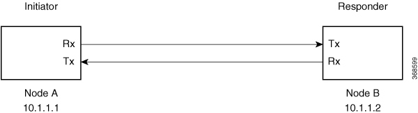
In this example, there are two nodes. The node with the lower IP address always acts as the initiator. In this case, node A (SITE-A) has the role of an initiator while Node B (SITE-B) has the role of a responder. In this example, the default IKE proposal and policy have been used on both nodes.

Figure 1. Configuration schema

The configuration on Node A is displayed in this table.

Node A (Initiator)

Keyring

RP/0/RP0/CPU0:SITE-A#configure
RP/0/RP0/CPU0:SITE-A(config)#keyring KR1
RP/0/RP0/CPU0:SITE-A(config-keyring-KR1)#peer SITE-B
RP/0/RP0/CPU0:SITE-A(config-keyring-KR1-peer-SITE-B)#address 10.0.0.2 255.255.255.0
RP/0/RP0/CPU0:SITE-A(config-keyring-KR1-peer-SITE-B)#pre-shared-key password 106D000A064743595
RP/0/RP0/CPU0:SITE-A(config-keyring-KR1-peer-SITE-B)#commit
RP/0/RP0/CPU0:SITE-A(config-keyring-KR1-peer-SITE-B)#exit
RP/0/RP0/CPU0:SITE-A(config-keyring-KR1)#exit

IKEv2 profile

RP/0/RP0/CPU0:SITE-A(config)#ikev2 profile IP1
RP/0/RP0/CPU0:SITE-A(config-ikev2-profile-IP1)#match identity remote address 10.0.0.2 255.255.255.0
RP/0/RP0/CPU0:SITE-A(config-ikev2-profile-IP1)#keyring KR1
RP/0/RP0/CPU0:SITE-A(config-ikev2-profile-IP1)#lifetime 86400
RP/0/RP0/CPU0:SITE-A(config-ikev2-profile-IP1)#commit
RP/0/RP0/CPU0:SITE-A(config-ikev2-profile-IP1)#exit

OTNSec policy

RP/0/RP0/CPU0:SITE-A(config)#otnsec policy OP1
RP/0/RP0/CPU0:SITE-A(config-otnsec-policy)#cipher-suite AES-GCM-256
RP/0/RP0/CPU0:SITE-A(config-otnsec-policy)#security-policy must-secure
RP/0/RP0/CPU0:SITE-A(config-otnsec-policy)#sak-rekey-interval 120
RP/0/RP0/CPU0:SITE-A(config-otnsec-policy)#commit
RP/0/RP0/CPU0:SITE-A(config-otnsec-policy)#exit

GCC interface for 1.2T and 1.2TL cards

RP/0/RP0/CPU0:SITE-A(config)#controller odu4 0/1/0/0/1
RP/0/RP0/CPU0:SITE-A(config-odu4)#gcc2
RP/0/RP0/CPU0:SITE-A(config-odu4)#commit
RP/0/RP0/CPU0:SITE-A(config-odu4)#exit
RP/0/RP0/CPU0:SITE-A(config)#interface GCC2 0/1/0/0/1
RP/0/RP0/CPU0:SITE-A(config-if)#ipv4 address 10.0.0.1 255.255.255.0
RP/0/RP0/CPU0:SITE-A(config-if)#commit
RP/0/RP0/CPU0:SITE-A(config-if)#exit

GCC interface for OTN-XP card

RP/0/RP0/CPU0:SITE-A(config)#controller oduc4 0/0/0/12
RP/0/RP0/CPU0:SITE-A(config-oduc4)#gcc2
RP/0/RP0/CPU0:SITE-A(config-oduc4)#commit
RP/0/RP0/CPU0:SITE-A(config-oduc4)#exit
RP/0/RP0/CPU0:SITE-A(config)#interface GCC2 0/0/0/12
RP/0/RP0/CPU0:SITE-A(config-if)#ipv4 address 10.0.0.1 255.255.255.0
RP/0/RP0/CPU0:SITE-A(config-if)#commit
RP/0/RP0/CPU0:SITE-A(config-if)#exit

OTNSec on ODU4 controller

RP/0/RP0/CPU0:SITE-A(config)#controller odu4 0/1/0/0/1
RP/0/RP0/CPU0:SITE-A(config-odu4)#otnsec
RP/0/RP0/CPU0:SITE-A(config-otnsec)#source ipv4 10.0.0.1
RP/0/RP0/CPU0:SITE-A(config-otnsec)#destination ipv4 10.0.0.2
RP/0/RP0/CPU0:SITE-A(config-otnsec)#session-id 9000
RP/0/RP0/CPU0:SITE-A(config-otnsec)#policy OP1
RP/0/RP0/CPU0:SITE-A(config-otnsec)#ikev2 IP1
RP/0/RP0/CPU0:SITE-A(config-otnsec)#commit
RP/0/RP0/CPU0:SITE-A(config-otnsec)#exit
RP/0/RP0/CPU0:SITE-A(config-odu4)#exit
RP/0/RP0/CPU0:SITE-B(config)#exit

OTNSec on ODUC4 controller

RP/0/RP0/CPU0:SITE-A(config)#controller oduc4 0/0/0/12
RP/0/RP0/CPU0:SITE-A(config-oduc4)#otnsec
RP/0/RP0/CPU0:SITE-A(config-otnsec)#source ipv4 10.0.0.1
RP/0/RP0/CPU0:SITE-A(config-otnsec)#destination ipv4 10.0.0.2
RP/0/RP0/CPU0:SITE-A(config-otnsec)#session-id 99
RP/0/RP0/CPU0:SITE-A(config-otnsec)#policy OP1
RP/0/RP0/CPU0:SITE-A(config-otnsec)#ikev2 IP1
RP/0/RP0/CPU0:SITE-A(config-otnsec)#commit
RP/0/RP0/CPU0:SITE-A(config-otnsec)#exit
RP/0/RP0/CPU0:SITE-A(config-oduc4)#exit
RP/0/RP0/CPU0:SITE-B(config)#exit

The configuration on Node B is displayed in this table.

Node B (Responder)

Keyring

RP/0/RP0/CPU0:SITE-B#configure
RP/0/RP0/CPU0:SITE-B(config)#keyring KR1
RP/0/RP0/CPU0:SITE-B(config-keyring-KR1)#peer SITE-A
RP/0/RP0/CPU0:SITE-B(config-keyring-KR1-peer-SITE-A)#address 10.0.0.1 255.255.255.0
RP/0/RP0/CPU0:SITE-B(config-keyring-KR1-peer-SITE-A)#pre-shared-key password 14341B180F547B7977
RP/0/RP0/CPU0:SITE-B(config-keyring-KR1-peer-SITE-A)#commit
RP/0/RP0/CPU0:SITE-B(config-keyring-KR1-peer-SITE-A)#exit
RP/0/RP0/CPU0:SITE-B(config-keyring-KR1)#exit

IKEv2 profile

RP/0/RP0/CPU0:SITE-B(config)#ikev2 profile IP1
RP/0/RP0/CPU0:SITE-B(config-ikev2-profile-IP1)#match identity remote address 10.0.0.1 255.255.255.0
RP/0/RP0/CPU0:SITE-B(config-ikev2-profile-IP1)#keyring KR1
RP/0/RP0/CPU0:SITE-B(config-ikev2-profile-IP1)#lifetime 86400
RP/0/RP0/CPU0:SITE-B(config-ikev2-profile-IP1)#commit
RP/0/RP0/CPU0:SITE-B(config-ikev2-profile-IP1)#exit

OTNSec policy

RP/0/RP0/CPU0:SITE-B(config)#otnsec policy OP1
RP/0/RP0/CPU0:SITE-B(config-otnsec-policy)#cipher-suite AES-GCM-256
RP/0/RP0/CPU0:SITE-B(config-otnsec-policy)#security-policy must-secure
RP/0/RP0/CPU0:SITE-B(config-otnsec-policy)#sak-rekey-interval 120
RP/0/RP0/CPU0:SITE-B(config-otnsec-policy)#commit
RP/0/RP0/CPU0:SITE-B(config-otnsec-policy)#exit

GCC interface for 1.2T and 1.2TL cards

RP/0/RP0/CPU0:SITE-B(config)#controller odu4 0/1/0/0/1
RP/0/RP0/CPU0:SITE-B(config-odu4)#gcc2
RP/0/RP0/CPU0:SITE-B(config-odu4)#commit
RP/0/RP0/CPU0:SITE-B(config-odu4)#exit
RP/0/RP0/CPU0:SITE-B(config)#interface GCC2 0/1/0/0/1
RP/0/RP0/CPU0:SITE-B(config-if)#ipv4 address 10.0.0.2 255.255.255.0
RP/0/RP0/CPU0:SITE-B(config-if)#commit
RP/0/RP0/CPU0:SITE-B(config-if)#exit

GCC interface for OTN-XP card

RP/0/RP0/CPU0:SITE-B(config)#controller oduc4 0/0/0/12
RP/0/RP0/CPU0:SITE-B(config-oduc4)#gcc2
RP/0/RP0/CPU0:SITE-B(config-oduc4)#commit
RP/0/RP0/CPU0:SITE-B(config-oduc4)#exit
RP/0/RP0/CPU0:SITE-B(config)#interface GCC2 0/0/0/12
RP/0/RP0/CPU0:SITE-B(config-if)#ipv4 address 10.0.0.2 255.255.255.0
RP/0/RP0/CPU0:SITE-B(config-if)#commit
RP/0/RP0/CPU0:SITE-B(config-if)#exit

OTNSec on ODU4 controller

RP/0/RP0/CPU0:SITE-B(config)#controller odu4 0/1/0/0/1
RP/0/RP0/CPU0:SITE-B(config-odu4)#otnsec
RP/0/RP0/CPU0:SITE-B(config-otnsec)#source ipv4 10.0.0.2
RP/0/RP0/CPU0:SITE-B(config-otnsec)#destination ipv4 10.0.0.1
RP/0/RP0/CPU0:SITE-B(config-otnsec)#session-id 9000
RP/0/RP0/CPU0:SITE-B(config-otnsec)#policy OP1
RP/0/RP0/CPU0:SITE-B(config-otnsec)#ikev2 IP1
RP/0/RP0/CPU0:SITE-B(config-otnsec)#commit
RP/0/RP0/CPU0:SITE-B(config-otnsec)#exit
RP/0/RP0/CPU0:SITE-B(config-odu4)#exit
RP/0/RP0/CPU0:SITE-B(config)#exit

OTNSec on ODUC4 controller

RP/0/RP0/CPU0:SITE-B(config)#controller oduc4 0/0/0/12
RP/0/RP0/CPU0:SITE-B(config-oduc4)#otnsec
RP/0/RP0/CPU0:SITE-B(config-otnsec)#source ipv4 10.0.0.2
RP/0/RP0/CPU0:SITE-B(config-otnsec)#destination ipv4 10.0.0.1
RP/0/RP0/CPU0:SITE-B(config-otnsec)#session-id 99
RP/0/RP0/CPU0:SITE-B(config-otnsec)#policy OP1
RP/0/RP0/CPU0:SITE-B(config-otnsec)#ikev2 IP1
RP/0/RP0/CPU0:SITE-B(config-otnsec)#commit
RP/0/RP0/CPU0:SITE-B(config-otnsec)#exit
RP/0/RP0/CPU0:SITE-B(config-oduc4)#exit
RP/0/RP0/CPU0:SITE-B(config)#exit

This reference enables you to replicate the sample IKEv2 and OTNSec configuration between two peers, showing both initiator and responder setup for multiple card types and controller variations.