Configuration Guide for Cisco NCS 1004, IOS XR Release 25.x.x

PDF

Configuration Guide for Cisco NCS 1004, IOS XR Release 25.x.x

1.2T and 1.2TL line cards

Want to summarize with AI?

Log in

This section explains the 1.2T and 1.2TL line cards for NCS 1004, which support muxponder and muxponder-slice operating modes for aggregating client traffic onto coherent DWDM trunk wavelengths.


A 1.2T or 1.2TL line card is a high-capacity optical line card that

  • provides trunk-side connectivity at rates from 100G to 1.2T using coherent DWDM optics,

  • supports muxponder and muxponder-slice card modes for flexible traffic aggregation, and

  • enables regeneration mode for extending optical signal reach through 3R processing.

Supported configurations on 1.2T and 1.2TL line cards

These configurations and procedures are supported on the 1.2T and 1.2TL line cards:

  • Card modes (muxponder and muxponder-slice)

  • Sub 50G configurations and split client port mapping

  • Supported data rates and client-to-trunk mapping

  • Regeneration mode configuration and verification

  • Bits-per-symbol (BPS) configuration

  • BPSK trunk rate configuration


Card modes

A card mode is an operational configuration for line cards that

  • determines how trunk ports and client ports are grouped and mapped,

  • allows either sequential or fixed mapping of client ports to trunk ports, and

  • supports independent or identical trunk rates depending on the mode chosen.

The line cards feature two trunk ports (numbered 0 and 1) and twelve client ports (numbered 2 through 13). You can configure the line card in two primary modes:
  • Muxponder mode: Both trunk ports are set to the same trunk rate. The client-to-trunk mapping follows a sequential arrangement, meaning all ports are grouped together and mapped in order.

  • Muxponder slice mode: Each trunk port can be set to a different trunk rate, operating independently of the other. The client-to-trunk mapping is fixed—client ports 2 through 7 are mapped to trunk port 0, and client ports 8 through 13 to trunk port 1.


Sub 50G configurations

A Sub 50G configuration is a line card setup that

  • enables data transmission rates below 50 Gbps or coupled mode on muxponder line cards,

  • allows flexible port assignments and mapping for various supported data rates, and

  • imposes specific requirements and operational restrictions when configured.

Standard port configurations for Sub 50G data rates

You can configure Sub 50G or coupled mode on the line card only when operating in muxponder mode. This table shows the supported port configurations for various data rates.

Table 1. Port configuration for supported data rates

Trunk data rate (per trunk)

Total configured data rate

Card support

Trunk ports

Client ports for trunk 0 (100G)

Shared client port (50G per trunk)

Client ports for trunk 1 (100G)

50G

100G

1.2T, 1.2TL

0, 1

-

2

-

150G

300G

1.2T, 1.2TL

0, 1

2

3

4

250G

500G

1.2T , 1.2TL

0, 1

2, 3

4

5, 6

350G

700G

1.2T , 1.2TL

0, 1

2, 3, 4

5

6, 7, 8

450G

900G

1.2T

0, 1

2, 3, 4, 5

6

7, 8, 9, 10

550G

1.1T

1.2T

0, 1

2, 3, 4, 5, 6

7

8, 9, 10, 11, 12

Alternate port configurations (split client port mapping)

From Release 7.5.2, 1.2T and 1.2TL line cards support an alternate port configuration for Sub 50G (split client port mapping), which you configure using CLI. This table shows the alternate port mapping for the supported data rates:
Table 2. Alternate port configuration for Sub 50G (Release 7.5.2 and later)

Trunk data rate (per trunk)

Total configured data rate

Card support

Trunk ports

Client ports for trunk 0 (100G)

Shared client port (50G per trunk)

Client ports for trunk 1 (100G)

50G

100G

1.2T, 1.2TL

0, 1

-

7

-

150G

300G

1.2T, 1.2TL

0, 1

2

7

8

250G

500G

1.2T , 1.2TL

0, 1

2, 3

7

8, 9

350G

700G

1.2T , 1.2TL

0, 1

2, 3, 4

7

8, 9, 10

450G

900G

1.2T

0, 1

2, 3, 4, 5

7

8, 9, 10, 11

550G

1.1T

1.2T

0, 1

2, 3, 4, 5, 6

7

8, 9, 10, 11, 12

Operational considerations

In all x50G configurations, client traffic on the middle port is affected by ODUK-BDI and LF alarms after a power cycle or link flap on the trunk side. This issue occurs when two network lanes operate in coupled mode and move from low to high power. To resolve this, create a new frame at the near-end or far-end by performing a shut or no shut of the trunk ports.

Restrictions for coupled mode configurations

These restrictions apply to coupled mode configuration:

  • Both trunk ports must be configured with the same bits-per-symbol or baud rate and must be sent over the same fiber and direction.

  • Chromatic dispersion values must be configured identically for both trunk ports.

  • When trunk internal loopback is configured, it must be set for both trunk ports. Configuring internal loopback on only one trunk results in traffic loss.

  • A fault on a trunk port of a coupled pair may cause errors on all clients, including those running only on the unaffected trunk port.

.

Configure the split client port mapping

Set up split client port mapping to efficiently allocate data rates and eliminate recabling on supported line cards.

Table 3. Feature History

Feature Name

Release Information

Description

Split Client Port Mapping

Cisco IOS XR Release 7.5.2

A new trunk port to client port mapping for sub 50G configurations is now available on the 1.2T C band, 1.2T L band, and 800G QSFP-DD Transponder line cards. In this mapping, the same shared client port is used for all Sub 50G trunk data rates, eliminating recabling while changing the data rates.

You can configure the trunk port to client port mapping for sub 50G data ratesin the default mode or in the split client port mapping mode.

In the default mode, consecutive client ports carry the information. For example, on a 2-QDD-C card, if the trunk data rate per trunk is 150G, client ports 2, 3, and 4 carry the data and client port 3 is the shared client port. For a trunk data rate of 250G, client ports 2, 3, 4, 5, and 6 carry the data and client port 4 is the shared client port. However, if you configure split client port mapping, trunk port to client port mapping is fixed. The shared client port is client port 5 for 2-QDD-C card and client port 7 for 1.2T and 1.2TL cards.

Follow these steps to configure and verify split client port mapping:

Procedure

1.

Run the configure hw-module location location mxponder split-client-port-mapping command to configure the split client port mapping.

Example:

This is a sample in which split-client-port-mapping is configured with a 450G trunk payload.


RP/0/RP0/CPU0:ios#configure
RP/0/RP0/CPU0:ios(config)#hw-module location 0/1 mxponder
RP/0/RP0/CPU0:ios(config-hwmod-mxp)#split-client-port-mapping
2.

Run the configure hw-module locationlocation mxponder no split-client-port-mapping command to remove the split client port-mapping configuration and configure default client port mapping.

Example:

This is a sample in which split client port-mapping configuration is removed.


RP/0/RP0/CPU0:ios#configure
RP/0/RP0/CPU0:ios(config)#hw-module location 0/1 mxponder
RP/0/RP0/CPU0:ios(config-hwmod-mxp)#no split-client-port-mapping
3.

Run the commit command to save and apply the split client port mapping configuration.

Example:


RP/0/RP0/CPU0:ios(config-hwmod-mxp)#commit
RP/0/RP0/CPU0:ios(config-hwmod-mxp)#end
4.

Run the show hw-module command to verify the port mapping configuration.

Example:

This is a sample output of the split client port-mapping.


RP/0/RP0/CPU0:ios#show hw-module location 0/1 mxponder
Location:             0/1
Client Bitrate:       100GE
Trunk  Bitrate:       450G
Status:               Provisioning In Progress
LLDP Drop Enabled:    FALSE
ARP Snoop Enabled:    FALSE
Client Port                     Mapper/Trunk Port          CoherentDSP0/1/0/0   CoherentDSP0/1/0/1
                                Traffic Split Percentage
HundredGigECtrlr0/1/0/2         ODU40/1/0/0/1                         100                        0
HundredGigECtrlr0/1/0/3         ODU40/1/0/0/2                         100                        0
HundredGigECtrlr0/1/0/4         ODU40/1/0/0/3                         100                        0
HundredGigECtrlr0/1/0/5         ODU40/1/0/0/4                         100                        0
HundredGigECtrlr0/1/0/7         ODU40/1/0/0/5                          50                       50
HundredGigECtrlr0/1/0/8         ODU40/1/0/1/1                           0                      100
HundredGigECtrlr0/1/0/9         ODU40/1/0/1/2                           0                      100
HundredGigECtrlr0/1/0/10        ODU40/1/0/1/3                           0                      100
HundredGigECtrlr0/1/0/11        ODU40/1/0/1/4                           0                      100

This is a sample output of the default client port mapping.


RP/0/RP0/CPU0:ios#show hw-module location 0/1 mxponder
Location:             0/1
Client Bitrate:       100GE
Trunk  Bitrate:       450G
Status:               Provisioning In Progress
LLDP Drop Enabled:    FALSE
ARP Snoop Enabled:    FALSE
Client Port                     Mapper/Trunk Port          CoherentDSP0/1/0/0   CoherentDSP0/1/0/1
                                Traffic Split Percentage

HundredGigECtrlr0/1/0/2         ODU40/1/0/0/1                         100                        0
HundredGigECtrlr0/1/0/3         ODU40/1/0/0/2                         100                        0
HundredGigECtrlr0/1/0/4         ODU40/1/0/0/3                         100                        0
HundredGigECtrlr0/1/0/5         ODU40/1/0/0/4                         100                        0
HundredGigECtrlr0/1/0/6         ODU40/1/0/0/5                          50                       50
HundredGigECtrlr0/1/0/7         ODU40/1/0/1/1                           0                      100
HundredGigECtrlr0/1/0/8         ODU40/1/0/1/2                           0                      100
HundredGigECtrlr0/1/0/9         ODU40/1/0/1/3                           0                      100
HundredGigECtrlr0/1/0/10        ODU40/1/0/1/4                           0                      100

The client port is configured in split mode, and individual lanes are mapped to independent sub-50G signals.


Supported data rates for 1.2T and 1.2TL line cards

This topic provides the supported client and trunk port data rates for muxponder and muxponder-slice configurations on 1.2T and 1.2TL line cards.

In Release 7.0.1, you can configure the client port to OTU4 only in the muxponder mode. In Release 7.1.1 and later releases, you can configure the client port to OTU4 in both the muxponder and muxponder slice modes. In muxponder slice mode, both the slices must be configured with either OTU4 or 100GE Ethernet client rates in Release 7.1.1. In Release 7.2.0, a mixed configuration of OTU4 and 100GE is supported in the muxponder slice mode. LLDP drop, L1 encryption, and AINS are not supported on the OTU4 configuration.

This table displays the client and trunk ports that are enabled for the muxponder configuration.

Table 4. Muxponder configuration table

Trunk data rate

Card support

Client data rate (100GE, OTU4)

Trunk ports

Client ports

100

1.2T, 1.2TL

100GE, OTU4

0, 1

2, 3

200

1.2T, 1.2TL

100GE, OTU4

0, 1

2, 3, 4, 5

300

1.2T, 1.2TL

100GE, OTU4

0, 1

2, 3, 4, 5, 6, 7

400

1.2T, 1.2TL

100GE, OTU4

0, 1

2, 3, 4, 5, 6, 7, 8, 9

500

1.2T

100GE, OTU4

0, 1

2, 3, 4, 5, 6, 7, 8, 9, 10, 11

600

1.2T

100GE, OTU4

0, 1

2, 3, 4, 5, 6, 7, 8, 9, 10, 11, 12, 13

This table displays the client and trunk ports that are enabled for the muxponder slice 0 configuration.

Table 5. Muxponder slice 0 configuration table

Trunk data rate

Card support

Client data rate

Trunk ports

Client ports

100

1.2T, 1.2TL

100GE, OTU4

0

2

200

1.2T, 1.2TL

100GE, OTU4

0

2, 3

300

1.2T, 1.2TL

100GE, OTU4

0

2, 3, 4

400

1.2T, 1.2TL

100GE, OTU4

0

2, 3, 4, 5

500

1.2T

100GE, OTU4

0

2, 3, 4, 5, 6

600

1.2T

100GE, OTU4

0

2, 3, 4, 5, 6, 7

This table displays the client and trunk ports that are enabled for the muxponder slice 1 configuration.

Table 6. Muxponder slice 1 configuration table

Trunk data rate

Card support

Client datarate

Trunk ports

Client ports

100

1.2T, 1.2TL

100GE, OTU4

1

8

200

1.2T, 1.2TL

100GE, OTU4

1

8, 9

300

1.2T, 1.2TL

100GE, OTU4

1

8, 9, 10

400

1.2T, 1.2TL

100GE, OTU4

1

8, 9, 10, 11

500

1.2T

100GE, OTU4

1

8, 9, 10, 11, 12

600

1.2T

100GE, OTU4

1

8, 9, 10, 11, 12, 13

All configurations can be accomplished by using appropriate values for client bitrate and trunk bitrate parameters of the hw-module command.

This table displays the trunk parameter ranges for the 1.2T card.

Table 7. Trunk parameter ranges for the 1.2T card

Trunk payload

FEC

Min BPS

Max BPS

Min GBd

Max GBd

50G

15%

1

1.3125

24.0207911

31.5272884

50G

27%

1

1.4453125

24.0207911

34.7175497

100G

15%

1

2.625

24.0207911

63.0545768

100G

27%

1

2.890625

24.0207911

69.4350994

150G

15%

1.3203125

3.9375

24.0207911

71.6359689

150G

27%

1.453125

4.3359375

24.0207911

71.6749413

200G

15%

1.7578125

5.25

24.0207911

71.7420962

200G

27%

2

4.40625

31.51

69.43

250G

15%

2.1953125

6

26.2727403

71.8059237

250G

27%

2.4140625

6

28.9312914

71.9068991

300G

15%

2.6328125

6

31.5272884

71.8485385

300G

27%

2.8984375

6

34.7175497

71.8681352

350G

15%

3.0703125

6

36.7818364

71.8790086

350G

27%

3.3828125

6

40.503808

71.8404724

400G

15%

3.5078125

6

42.0363845

71.9018782

400G

27%

3.8671875

6

46.2900663

71.8197392

450G

15%

3.9453125

6

47.2909326

71.9196757

450G

27%

4.34375

6

52.0763245

71.9327648

500G

15%

4.3828125

6

52.5454806

71.93392

500G

27%

4.8281250

6

57.8625828

71.9068991

550G

15%

4.8203125

6

57.8000287

71.9455787

550G

27%

5.3125

6

63.6488411

71.88575

600G

15%

5.2578125

-

-

71.9552971

This table displays the trunk parameter ranges for the 1.2TL card.

Table 8. Trunk parameter ranges for the 1.2TL card

Trunk payload

FEC

Min BPS

Max BPS

Min GBd

Max GBd

100G

15%

1

2.625

24.0207911

63.0545768

100G

27%

1

2.890625

24.0207911

69.4350994

150G

15%

1.3203125

3.9375

24.0207911

71.6359689

150G

27%

1.453125

4.3359375

24.0207911

71.6749413

200G

15%

2

4

31.5272884

63.0545768

200G

27%

2

4.40625

31.51664088

69.43509943

250G

15%

2.1953125

4.5

35.0303204

71.8059237

250G

27%

2.4140625

4.5

38.5750552

71.9068991

300G

15%

2.6328125

4.5

42.0363845

71.8485385

300G

27%

2.8984375‬

4.5

46.2900662857142

71.86813526

350G

15%

3.0703125

4.5

49.0424486

71.8790086

350G

27%

3.3828125

4.5

54.0050773

71.8404724

400G

15%

3.5078125

4.5

56.0485127

71.9018782

400G

27%

3.8671875

4.5

61.72008838

71.81973921

To configure the BPS, see Configure the BPS.


1.2T card interoperability with OTN-XP card

A card interoperability is a network capability that

  • enables different types of optical interface cards to exchange and transport data,

  • allows client cards to aggregate and convert multiple traffic streams for trunk transmission, and

  • requires compatible pluggable optics to ensure reliable communication between platforms.

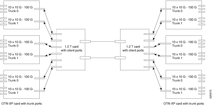
The OTN-XP card can be interoperable with the 1.2T card. In an interoperability scenario, the 1.2T card can serve as a trunk port and the OTN-XP card can serve as a client port. The trunk port of OTN-XP can converge 10 x 10 G traffic and transmit as 100G traffic in the OTU4 mode. This OTU4 traffic can further be multiplexed to a higher bandwidth DWDM signal by connecting to 1.2T OTU4 client interface.

Additional reference information

For interoperability between the 1.2T and OTN-XP cards, supported pluggable optics are required:

  • On the trunk side (OTN-XP card): Cisco QSFP-100G-LR4 Pluggable Optics Module (ONS-QSFP28-LR4). The same module should be used on the client side of the 1.2T card to ensure compatibility.

  • On the client side (OTN-XP card):

    • ONS-QSFP-4x10-MLR

    • QSFP-40G-SR4


Prerequisites for interoperability with OTN-XP card

  • Configure the OTN-XP card in the 10x10G traffic mode.

  • Configure the 1.2T card in the OTU4 client mode with supported trunk rate.

  • Ensure that the software installed on both route processors and cards are stable in the supported traffic modes for the 1.2T and OTN-XP card.


Scenario on interoperability with OTN-XP card

Consider a topology in which the OTN-XP card is configured in 10x10G traffic mode and the 1.2T card is configured in OUT4 client mode with a supported trunk rate.

For the solution to work, the OTN-XP trunk optics must interoperate seamlessly with the 1.2T client optics.

Interoperability scenario

Figure 1. Interoperability Topology

Configure the interoperability between 1.2T and OTN-XP line cards

Use this procedure to configure the NCS 1004 for interoperability between 1.2T and OTN-XP line cards, where 100GE client traffic from the OTN-XP card is aggregated over a 1.2T trunk wavelength.

Before you begin

Ensure the following conditions are met before starting this configuration:

  • The OTN-XP card is installed and in POWERED_ON state.

  • The 1.2T card is installed and running in muxponder or muxponder-slice mode.

  • The trunk rates to be used between the two cards are planned and compatible.

Procedure

1.

Run the lc-module location lcmode command to configure the OTN-XP card LC mode to 4x100G-MXP-400G-TXP.

Example:

RP/0/RP0/CPU0:ios(config)#lc-module location <otn-xp-location> lcmode 4x100G-MXP-400G-TXP
RP/0/RP0/CPU0:ios(config)#commit

For full details about configuring the LC mode, see Configure the LC mode.

2.

Run the hw-module location mxponder-slice 0 command to configure the OTN-XP card mxponder-slice 0 with 100GE client ports and a 400G trunk rate.

Example:

RP/0/RP0/CPU0:ios(config)#hw-module location <otn-xp-location> mxponder-slice 0
RP/0/RP0/CPU0:ios(config-hwmod-mxp)#trunk-rate 400G
RP/0/RP0/CPU0:ios(config-hwmod-mxp)#client-port-rate 1 client-type 100GE
RP/0/RP0/CPU0:ios(config-hwmod-mxp)#client-port-rate 6 client-type 100GE
RP/0/RP0/CPU0:ios(config-hwmod-mxp)#client-port-rate 7 client-type 100GE
RP/0/RP0/CPU0:ios(config-hwmod-mxp)#client-port-rate 10 client-type 100GE
RP/0/RP0/CPU0:ios(config-hwmod-mxp)#commit
3.

Run the hw-module location mxponder-slice 0 command to configure the 1.2T card mxponder-slice 0 with a 100GE client rate and 400G trunk rate to receive the OTN-XP client traffic.

Example:

RP/0/RP0/CPU0:ios(config)#hw-module location <12t-location> mxponder-slice 0
RP/0/RP0/CPU0:ios(config-hwmod-mxp)#client-rate 100GE
RP/0/RP0/CPU0:ios(config-hwmod-mxp)#trunk-rate 400G
RP/0/RP0/CPU0:ios(config-hwmod-mxp)#commit
4.

Run the show hw-module location mxponder-slice commands to verify the configuration on both cards.

Example:

RP/0/RP0/CPU0:ios#show hw-module location <otn-xp-location> mxponder-slice 0
RP/0/RP0/CPU0:ios#show hw-module location <12t-location> mxponder-slice 0

The output confirms that both cards are in Provisioned state, with matching 400G trunk rates and 100GE client rates.

The NCS 1004 is configured for interoperability between the 1.2T and OTN-XP line cards. The 100GE client traffic from the OTN-XP card is aggregated and carried over the 1.2T trunk wavelength at 400G.

What to do next

Confirm that both cards display Status Provisioned with matching trunk rates, and verify end-to-end connectivity using appropriate traffic tests.


Configure the card mode

Configure the operating mode for 1.2T and 1.2TL line cards to match your network requirements.

The 1.2T and 1.2TL line cards support two primary card modes: muxponder and muxponder-slice. In muxponder mode, all client ports are mapped to both trunk ports. In muxponder-slice mode, client ports are divided into two independent slices, each with its own trunk port. Choose the appropriate subtask based on your configuration need.

Follow these steps to configure the card mode and verify your settings:

Procedure

1.

Run the hw-module location location mxponder client-rate {100GE | OTU4} hw-module location location mxponder trunk-rate {50G | 100G150G | 200G | 250G | 300G | 350G | 400G | 450G | 500G | 550G | 600G } command to configure the card in the muxponder mode.

Example:

This is a sample in which the card is configured in the muxponder mode with a 550G trunk payload.


RP/0/RP0/CPU0:ios#config
Tue Oct 15 01:24:56.355 UTC
RP/0/RP0/CPU0:ios(config)#hw-module location 0/1 mxponder client-rate 100GE
RP/0/RP0/CPU0:ios(config)#hw-module location 0/1 mxponder trunk-rate 550G
RP/0/RP0/CPU0:ios(config)#commit

This is a sample in which the card is configured in the muxponder mode with a 500G trunk payload.


RP/0/RP0/CPU0:ios#config
Sun Feb 24 14:09:33.989 UTC
RP/0/RP0/CPU0:ios(config)#hw-module location 0/2 mxponder client-rate OTU4
RP/0/RP0/CPU0:ios(config)#hw-module location 0/2 mxponder trunk-rate 500G
RP/0/RP0/CPU0:ios(config)#commit
2.

Run the hw-module location location mxponder-slice mxponder-slice-number client-rate { 100GE|OTU4} hw-module location location mxponder-slice trunk-rate { 100G | 200G | 300G | 400G | 500G | 600G } to configure the card in the muxponder slice mode.

Example:

This is a sample in which the card is configured in the muxponder slice 0 mode with a 500G trunk payload.


RP/0/RP0/CPU0:ios#config
RP/0/RP0/CPU0:ios(config)#hw-module location 0/1 mxponder-slice 0 client-rate 100GE
RP/0/RP0/CPU0:ios(config)#hw-module location 0/1 mxponder-slice 0 trunk-rate 500G
RP/0/RP0/CPU0:ios(config)#commit

This is a sample in which the card is configured in the muxponder slice 1 mode with a 400G trunk payload.


RP/0/RP0/CPU0:ios#config
RP/0/RP0/CPU0:ios(config)#hw-module location 0/1 mxponder-slice 1 client-rate 100GE
RP/0/RP0/CPU0:ios(config)#hw-module location 0/1 mxponder-slice 1 trunk-rate 400G
RP/0/RP0/CPU0:ios(config)#commit

This is a sample in which the card is configured with mixed client rates in the muxponder slice mode.


RP/0/RP0/CPU0:ios#configure
Mon Mar 23 06:10:22.227 UTC
RP/0/RP0/CPU0:ios(config)#hw-module location 0/1 mxponder-slice 0 client-rate OTU4 trunk-rate 500G 
RP/0/RP0/CPU0:ios(config)#hw-module location 0/1 mxponder-slice 1 client-rate 100GE trunk-rate 500G
RP/0/RP0/CPU0:ios(config)#commit
3.

Run the show hw-module location to verify the card configurations.

Example:


RP/0/RP0/CPU0:ios#show hw-module location 0/2 mxponder
Fri Mar 15 11:48:48.344 IST

Location:             0/2
Client Bitrate:       100GE
Trunk  Bitrate:       500G
Status:               Provisioned
LLDP Drop Enabled:    FALSE
Client Port            Mapper/Trunk Port   CoherentDSP0/2/0/0  CoherentDSP0/2/0/1
                     Traffic Split Percentage

HundredGigECtrlr0/2/0/2  ODU40/2/0/0/1                100                   0
HundredGigECtrlr0/2/0/3  ODU40/2/0/0/2                100                   0
HundredGigECtrlr0/2/0/4  ODU40/2/0/0/3                100                   0
HundredGigECtrlr0/2/0/5  ODU40/2/0/0/4                100                   0
HundredGigECtrlr0/2/0/6  ODU40/2/0/0/5                100                   0
HundredGigECtrlr0/2/0/7  ODU40/2/0/1/1                  0                 100
HundredGigECtrlr0/2/0/8  ODU40/2/0/1/2                  0                 100
HundredGigECtrlr0/2/0/9  ODU40/2/0/1/3                  0                 100
HundredGigECtrlr0/2/0/10 ODU40/2/0/1/4                  0                 100
HundredGigECtrlr0/2/0/11 ODU40/2/0/1/5                  0                 100

This is a sample ouput of the coupled mode configuration where the shared client port is highlighted.


RP/0/RP0/CPU0:ios#show hw-module location 0/1 mxponder
Tue Oct 15 01:25:57.358 UTC

Location:             0/1
Client Bitrate:       100GE
Trunk  Bitrate:       550G
Status:               Provisioned
LLDP Drop Enabled:    FALSE
Client Port           Mapper/Trunk Port    CoherentDSP0/1/0/0 CoherentDSP0/1/0/1
                   Traffic Split Percentage

HundredGigECtrlr0/1/0/2    ODU40/1/0/0/1             100                   0
HundredGigECtrlr0/1/0/3    ODU40/1/0/0/2             100                   0
HundredGigECtrlr0/1/0/4    ODU40/1/0/0/3             100                   0
HundredGigECtrlr0/1/0/5    ODU40/1/0/0/4             100                   0
HundredGigECtrlr0/1/0/6    ODU40/1/0/0/5             100                   0
HundredGigECtrlr0/1/0/7    ODU40/1/0/0/6              50                  50
HundredGigECtrlr0/1/0/8    ODU40/1/0/1/1               0                 100
HundredGigECtrlr0/1/0/9    ODU40/1/0/1/2               0                 100
HundredGigECtrlr0/1/0/10   ODU40/1/0/1/3               0                 100
HundredGigECtrlr0/1/0/11   ODU40/1/0/1/4               0                 100
HundredGigECtrlr0/1/0/12   ODU40/1/0/1/5               0                 100

This is a sample ouput of all the muxponder slice 0 configurations.


RP/0/RP0/CPU0:ios#show hw-module location 0/1 mxponder-slice  0
Fri Mar 15 06:04:18.348 UTC

Location:             0/1
Slice ID:             0
Client Bitrate:       100GE
Trunk  Bitrate:       500G
Status:               Provisioned
LLDP Drop Enabled:    FALSE
Client Port                     Mapper/Trunk Port          CoherentDSP0/1/0/0
                                Traffic Split Percentage

HundredGigECtrlr0/1/0/2         ODU40/1/0/0/1                      100
HundredGigECtrlr0/1/0/3         ODU40/1/0/0/2                      100
HundredGigECtrlr0/1/0/4         ODU40/1/0/0/3                      100
HundredGigECtrlr0/1/0/5         ODU40/1/0/0/4                      100
HundredGigECtrlr0/1/0/6         ODU40/1/0/0/5                      100

This is a sample ouput of all the muxponder slice 1 configurations.


RP/0/RP0/CPU0:ios#show hw-module location 0/1 mxponder-slice 1
Fri Mar 15 06:11:50.020 UTC

Location:             0/1
Slice ID:             1
Client Bitrate:       100GE
Trunk  Bitrate:       400G
Status:               Provisioned
LLDP Drop Enabled:    TRUE
Client Port                     Mapper/Trunk Port          CoherentDSP0/1/0/1
                                Traffic Split Percentage

HundredGigECtrlr0/1/0/8         ODU40/1/0/1/1                      100
HundredGigECtrlr0/1/0/9         ODU40/1/0/1/2                      100
HundredGigECtrlr0/1/0/10        ODU40/1/0/1/3                      100
HundredGigECtrlr0/1/0/11        ODU40/1/0/1/4                      100

This is a sample ouput of the muxponder slice 1 configuration with client configured as OTU4.


RP/0/RP0/CPU0:ios#sh hw-module location 0/0 mxponder-slice 1                                                            
Wed Mar 11 13:59:11.073 UTC 

Location:             0/0
Slice ID:             1  
Client Bitrate:       OTU4
Trunk  Bitrate:       200G
Status:               Provisioned
Client Port                     Peer/Trunk Port            CoherentDSP0/0/0/1  
                              Traffic Split Percentage
OTU40/0/0/8                     ODU40/0/0/1/1                      100
OTU40/0/0/9                     ODU40/0/0/1/2                      100

This is a sample to verify the mixed client rate configuration in the muxponder slice mode.


RP/0/RP0/CPU0:ios#show hw-module location 0/1 mxponder
Mon Mar 23 06:20:22.227 UTC

Location:             0/1
Slice ID:             0
Client Bitrate:       OTU4
Trunk  Bitrate:       500G
Status:               Provisioned
Client Port                     Peer/Trunk Port            CoherentDSP0/1/0/0   
                                Traffic Split Percentage

OTU40/1/0/2                     ODU40/1/0/0/1                      100
OTU40/1/0/3                     ODU40/1/0/0/2                      100
OTU40/1/0/4                     ODU40/1/0/0/3                      100
OTU40/1/0/5                     ODU40/1/0/0/4                      100
OTU40/1/0/6                     ODU40/1/0/0/5                      100


Location:             0/1
Slice ID:             1
Client Bitrate:       100GE
Trunk  Bitrate:       500G
Status:               Provisioned
LLDP Drop Enabled:    FALSE
ARP Snoop Enabled:    FALSE
Client Port                     Mapper/Trunk Port          CoherentDSP0/1/0/1   
                                Traffic Split Percentage

HundredGigECtrlr0/1/0/8         ODU40/1/0/1/1                         100
HundredGigECtrlr0/1/0/9         ODU40/1/0/1/2                         100
HundredGigECtrlr0/1/0/10        ODU40/1/0/1/3                         100
HundredGigECtrlr0/1/0/11        ODU40/1/0/1/4                         100
HundredGigECtrlr0/1/0/12        ODU40/1/0/1/5                         100
4.

Run the clear counters controller controllertype R/S/I/P command to clear alarm statistics on the optics or coherent DSP controller.

Example:

This is a sample in which the alarm statistics are cleared on the coherent DSP controller.


RP/0/RP0/CPU0:ios#show controller coherentDSP 0/1/0/0
Tue Jun 11 05:15:12.540 UTC

Port                                            : CoherentDSP 0/1/0/0
Controller State                                : Up
Inherited Secondary State                       : Normal
Configured Secondary State                      : Normal
Derived State                                   : In Service
Loopback mode                                   : None
BER Thresholds                                  : SF = 1.0E-5  SD = 1.0E-7
Performance Monitoring                          : Enable

Alarm Information:
LOS = 1 LOF = 1 LOM = 0
OOF = 1 OOM = 1 AIS = 0
IAE = 0 BIAE = 0        SF_BER = 0
SD_BER = 2      BDI = 2 TIM = 0
FECMISMATCH = 0 FEC-UNC = 0
Detected Alarms                                 : None

Bit Error Rate Information
PREFEC  BER                                     : 8.8E-03
POSTFEC BER                                     : 0.0E+00

TTI :
        Remote hostname                         : P2B8
        Remote interface                        : CoherentDSP 0/1/0/0
        Remote IP addr                          : 0.0.0.0

FEC mode                                        : Soft-Decision 15

AINS Soak                                       : None
AINS Timer                                      : 0h, 0m
AINS remaining time                             : 0 seconds
RP/0/RP0/CPU0:ios#clear counters controller coherentDSP 0/1/0/0
Tue Jun 11 05:17:07.271 UTC
All counters are cleared
RP/0/RP0/CPU0:ios#show controllers coherentDSP 0/1/0/1
Tue Jun 11 05:20:55.199 UTC

Port                                            : CoherentDSP 0/1/0/1
Controller State                                : Up
Inherited Secondary State                       : Normal
Configured Secondary State                      : Normal
Derived State                                   : In Service
Loopback mode                                   : None
BER Thresholds                                  : SF = 1.0E-5  SD = 1.0E-7
Performance Monitoring                          : Enable

Alarm Information:
LOS = 0 LOF = 0 LOM = 0
OOF = 0 OOM = 0 AIS = 0
IAE = 0 BIAE = 0        SF_BER = 0
SD_BER = 0      BDI = 0 TIM = 0
FECMISMATCH = 0 FEC-UNC = 0
Detected Alarms                                 : None

Bit Error Rate Information
PREFEC  BER                                     : 1.2E-02
POSTFEC BER                                     : 0.0E+00

TTI :
        Remote hostname                         : P2B8
        Remote interface                        : CoherentDSP 0/1/0/1
        Remote IP addr                          : 0.0.0.0

FEC mode                                        : Soft-Decision 15

AINS Soak                                       : None
AINS Timer                                      : 0h, 0m
AINS remaining time                             : 0 seconds

Regeneration modes

A regeneration mode is an operational mode for line cards that

  • enables 3R (reamplify, reshape, retime) regeneration to extend optical signal reach,

  • receives an OTN signal on one trunk port and retransmits the regenerated signal on the other trunk port, and

  • creates only trunk optics controllers and CoherentDSP controllers (no client ports are used).

Supported trunk rates for regeneration mode

In regeneration mode, optical signals are corrected by converting them to an electrical signal, processing the signal, and retransmitting it as an optical signal. The supported trunk rates for regeneration mode are:

  • 1.2T card—100G to 600G in multiples of 100G

  • 1.2TL card—200G to 400G in multiples of 100G

  • 2-QDD-C card—200G to 400G in multiples of 100G


Configure the card in regen mode

Enable 3R signal regeneration on trunk ports using the regeneration mode on supported line cards.

In regen mode, the OTN signal is received on one trunk port and the regenerated OTN signal is sent on the other trunk port. Only trunk optics controllers and CoherentDSP controllers are created in this mode. Use the hw-module location regen trunk-rate commands to configure regen mode.

Follow these steps to configure the 1.2T, 1.2TL, or 2-QDD-C line card in regeneration (regen) mode.

Procedure

1.

Run the configure hw-module location regentrunk-rate trunk-rate to configure regen mode on 1.2T, 1.2TL, and 2-QDD-C cards.

Example:

This is a sample to configure the regen mode on 1.2T, 1.2TL, and 2-QDD-C line cards with the trunk-rate 300.


RP/0/RP0/CPU0:ios#configure
RP/0/RP0/CPU0:ios(config)#hw-module location 0/0 
RP/0/RP0/CPU0:ios(config-hwmod)#regen
RP/0/RP0/CPU0:ios(config-regen)#trunk-rate 300
RP/0/RP0/CPU0:ios(config-regen)#commit
RP/0/RP0/CPU0:ios(config-regen)#exit
2.

Run the commit command to save and apply the regen configuration, then exit the regen configuration mode.

Example:


RP/0/RP0/CPU0:ios(config-regen)#commit
RP/0/RP0/CPU0:ios(config-regen)#exit

Verify the regen mode

Ensure that regen mode is active and functioning on supported line cards.

Follow these steps to verify regen mode configuration on supported line cards:

Procedure

Run the show hw-module location location regen to verify the regen mode on 1.2T, 1.2TL, and 2-QDD-C cards.

Example:


RP/0/RP0/CPU0:ios#show hw-module location 0/0 regen
Mon Mar 25 09:50:42.936 UTC

Location:             0/0
Trunk  Bitrate:       400G
Status:               Provisioned
East Port 	            West Port
CoherentDSP0/0/0/0      CoherentDSP0/0/0/1

The terms, East Port and West Port are used to represent OTN signal regeneration at the same layer.


Configure the BPS

Set the BPS value on the optics controller to ensure compatibility with target trunk rates.

You can configure the BPS value on the optics controller to 3.4375 to support 300G trunk configurations on 75 GHz networks. The BPS value affects the modulation format, baud rate, and optical reach.

Follow these steps to configure the bits-per-symbol (BPS) value:

Procedure

1.

Run the configure controller optics R/S/I/P bits-per-symbol 3.4375 command to configure the Bits per Symbol (BPS) to 3.4375 to support 300G trunk configurations on 75 GHz.

Example:

This is a sample in which the BPS is configured to 3.4375.


RP/0/RP0/CPU0:ios#configure
Wed Mar 27 14:12:49.932 UTC
RP/0/RP0/CPU0:ios(config)#controller optics 0/3/0/0 bits-per-symbol 3.4375
RP/0/RP0/CPU0:ios(config)#commit
2.

Run the show controller optics R/S/I/P bps-range bps-range | include data-rate | include fec-type command to view the BPS for a specific range.

Example:


RP/0/RP0/CPU0:ios#show controllers optics 0/3/0/0 bps-range 3 3.05 | include 300G | include SD27
Thu Mar 28 03:01:39.751 UTC
300G            SD27            3.0000000       69.4350994
300G            SD27            3.0078125       69.2547485
300G            SD27            3.0156250       69.0753320
300G            SD27            3.0234375       68.8968428
300G            SD27            3.0312500       68.7192736
300G            SD27            3.0390625       68.5426174
300G            SD27            3.0468750       68.3668671
3.

Run the show controller optics R/S/I/P baud-rate-range baud-range | include data-rate | include fec-type to view the baud for a specific range.

Example:


RP/0/RP0/CPU0:ios#show controllers optics 0/3/0/0 baud-rate-range 43 43.4 | include 300G | include SD27
Thu Mar 28 03:12:36.521 UTC
300G            SD27            4.8046875       43.3545986
300G            SD27            4.8125000       43.2842178
300G            SD27            4.8203125       43.2140651
300G            SD27            4.8281250       43.1441394
300G            SD27            4.8359375       43.0744397
300G            SD27            4.8437500       43.0049648

BPSK trunk rates

A BPSK trunk rate is a trunk-rate operating mode that

  • uses binary phase shift keying (1 bit per symbol) to maximize optical reach in long-haul and ultra-long-haul scenarios,

  • trades capacity for distance by reducing the modulation complexity compared to QPSK or higher-order formats, and

  • allows fine-grained baud rate tuning through the bits-per-symbol configuration to optimize the distance-capacity tradeoff.

From Release 7.2.1, you can configure trunk rates of 50G, 100G, and 150G to support Binary Phase-Shift Keying (BPSK) modulation. The BPSK modulation enables information to be carried over radio signals more efficiently.

You can configure trunk rates for BPSK using CLI, NetConf YANG, and OC models.

This table list the 50G, 100G, and 150G trunk rates with the supported BPSK modulation:

Trunk rate

BPSK modulation

50G

1 to 1.4453125

100G

1 to 2.890625

150G

1.453125 to 4.3359375


Configure the BPSK trunk rate ranges

Set and confirm trunk rates for BPSK modulation to optimize transmission on supported hardware.
Follow these steps to configure and verify the BPSK trunk rate:

Procedure

1.

Run the configure hw-module location location mxponder trunk-rate {50G | 100G | 150G} command to configure the trunk rate for BPSK modulation.

Example:

This example shows how to configure trunk rate to 50G:


RP/0/RP0/CPU0:(config)#hw-module location 0/0 mxponder
RP/0/RP0/CPU0:(config-hwmod-mxp)#trunk-rate 50G 
RP/0/RP0/CPU0:(config-hwmod-mxp)#commit    
2.

Run the show commands to view the trunk rate configured for the BPSK modulation.

Example:


RP/0/RP0/CPU0:ios(hwmod-mxp)#show hw-module location 0/0 mxponder                                                                                
Tue Feb 25 11:13:41.934 UTC                                                                                                                                    

Location:             0/0
Client Bitrate:       100GE
Trunk  Bitrate:       50G  
Status:               Provisioned
LLDP Drop Enabled:    FALSE                   
ARP Snoop Enabled:    FALSE                   
Client Port                     Mapper/Trunk Port          CoherentDSP0/0/0/0   CoherentDSP0/0/0/1      
                                Traffic Split Percentage                                                

HundredGigECtrlr0/0/0/2         ODU40/0/0/0                            50                       50


RP/0/RP0/CPU0:ios#show controllers optics 0/0/0/0
Thu Mar  5 07:12:55.681 UTC                          

Controller State: Up 

Transport Admin State: In Service 

Laser State: On 

LED State: Green 
                  
 Optics Status    

         Optics Type:  DWDM optics
         DWDM carrier Info: C BAND, MSA ITU Channel=61, Frequency=193.10THz,
         Wavelength=1552.524nm                                              

         Alarm Status:
         -------------
         Detected Alarms: None


         LOS/LOL/Fault Status:

         Alarm Statistics:

         -------------
         HIGH-RX-PWR = 0            LOW-RX-PWR = 2          
         HIGH-TX-PWR = 0            LOW-TX-PWR = 0          
         HIGH-LBC = 0               HIGH-DGD = 0            
         OOR-CD = 0                 OSNR = 0                
         WVL-OOL = 0                MEA  = 0                
         IMPROPER-REM = 0                                   
         TX-POWER-PROV-MISMATCH = 0                         
         Laser Bias Current = 0.0 %                         
         Actual TX Power = 1.97 dBm                         
         RX Power = 1.58 dBm                                
         RX Signal Power = 0.60 dBm                         
         Frequency Offset = 386 MHz                         

         Performance Monitoring: Enable 

         THRESHOLD VALUES
         ----------------

         Parameter                 High Alarm  Low Alarm  High Warning  Low Warning
         ------------------------  ----------  ---------  ------------  -----------
         Rx Power Threshold(dBm)          4.9      -12.0           0.0          0.0
         Tx Power Threshold(dBm)          3.5      -10.1           0.0          0.0
         LBC Threshold(mA)                N/A        N/A          0.00         0.00

         Configured Tx Power = 2.00 dBm
         Configured CD High Threshold = 180000 ps/nm
         Configured CD lower Threshold = -180000 ps/nm
         Configured OSNR lower Threshold = 0.00 dB
         Configured DGD Higher Threshold = 180.00 ps
         Baud Rate =  34.7175521851 GBd
         Bits per Symbol = 1.0000000000  bits/symbol
         Modulation Type: BPSK
         Chromatic Dispersion -9 ps/nm
         Configured CD-MIN -180000 ps/nm  CD-MAX 180000 ps/nm
         Polarization Mode Dispersion = 0.0 ps
         Second Order Polarization Mode Dispersion = 125.00 ps^2
         Optical Signal to Noise Ratio = 34.60 dB
         SNR = 20.30 dB
         Polarization Dependent Loss = 0.20 dB
         Polarization Change Rate = 0.00 rad/s
         Differential Group Delay = 2.00 ps
         Filter Roll Off Factor : 0.100
         Rx VOA Fixed Ratio : 15.00 dB
         Enhanced Colorless Mode : 0
         Enhanced SOP Tolerance Mode : 0
         NLEQ Compensation Mode : 0
         Cross Polarization Gain Mode : 0
         Cross Polarization Weight Mode : 0
         Carrier Phase Recovery Window : 0
         Carrier Phase Recovery Extended Window : 0
AINS Soak                : None
AINS Timer               : 0h, 0m
AINS remaining time      : 0 seconds