Interfaces and Hardware Component Configuration Guide for Cisco 8000 Series Routers, Cisco IOS XR Releases

PDF

Interfaces and Hardware Component Configuration Guide for Cisco 8000 Series Routers, Cisco IOS XR Releases

IP-in-IP tunnels

Want to summarize with AI?

Log in

This topic describes IP-in-IP tunneling on the Cisco 8000 Series Router, which encapsulates one IP packet as a payload within another IP packet to transport traffic across an intermediate IP network.


IP-in-IP tunneling is a mechanism that

  • provides transport of packets of one protocol within another protocol through encapsulation

  • encapsulates and decapsulates an IP packet as a payload in another IP packet, and

  • supports all four combinations of inner and outer IP versions: IPv4 over IPv4, IPv6 over IPv4, IPv4 over IPv6, and IPv6 over IPv6.

For example, an IPv4 over IPv6 refers to an IPv4 packet as a payload encapsulated within an IPv6 packet and routed across an IPv6 network to reach the destination IPv4 network, where it is decapsulated.

Table 1. Feature History Table

Feature Name

Release Information

Feature Description

IPv4 packets with IPv6 outer header

Release 26.1.1

Introduced in this release on: Centralized Systems (8400 [ASIC:K100]) )(select variants only*)

*This feature is now supported on Cisco 8404-SYS-D routers.

IPv4 packets with IPv6 outer header

Release 25.4.1

Introduced in this release on: Fixed Systems (8700 [ASIC: K100], 8010 [ASIC: A100])(select variants only*)

*This feature is now supported on:

  • 8711-48Z-M

  • 8011-32Y8L2H2FH

  • 8011-12G12X4Y-A/D

Increased IP-in-IP tunnel scale for gRIBI-based nexthops

Release 25.4.1

Introduced in this release on: Fixed Systems (8200 [ASIC: Q200 ]); Centralized Systems (8600 [ASIC:Q200]) ; Modular Systems (8800 [LC ASIC: Q200])

This feature enables the router to efficiently load balance and manage high traffic volumes by increasing the scale for encapsulation and decapsulation nexthops programmed using gRPC Routing Information Base Interface (gRIBI) to 12K IP-in-IP tunnels.

This feature introduces these changes:

CLI: The hw-module profile cef iptunnel scale command is modified.

Increase in IP-in-IP decapsulation tunnels support

Release 25.3.1

Introduced in this release on: Fixed Systems (8200 [ASIC: Q200]; Centralized Systems (8600 [ASIC:Q200]); Modular Systems (8800 [LC ASIC: Q200])

With this release, we have revised the maximum number of IPv4 and IPv6 IP-in-IP decapsulation tunnels from 64 to 200 on Cisco Silicon One Q200 ASIC-based systems. An increased number enhances the router's ability to support larger and more complex IP-in-IP tunneling scenarios improving scalability, efficiency, and flexibility in network design.

IPv4 packets with IPv6 outer header

Release 25.1.1

Introduced in this release on: Fixed Systems (8010 [ASIC: A100])(select variants only*)

*This feature is supported on Cisco 8011-4G24Y4H-I routers.

IPv4 packets with IPv6 outer header

Release 24.4.1

Introduced in this release on: Fixed Systems(8200, 8700)(select variants only*); Modular Systems (8800 [LC ASIC: P100])(select variants only*).

This feature that allows decapsulation of IPv4 and IPv6 tunnels with IPv6 headers helps the administrators to benefit from an improved IPv6 routing and security without upgrading their entire network to IPv6.

*This feature is now supported on:

  • 8212-48FH-M

  • 8711-32FH-M

  • 8712-MOD-M

  • 88-LC1-12TH24FH-E

  • 88-LC1-52Y8H-EM

  • 88-LC1-36EH

IPv4 packets with IPv6 outer header

Release 7.5.3

With this release, decapsulation of IPv4 and IPv6 tunnels with IPv6 outer headers are supported.

This feature helps the administrators to take advantage of the benefits of IPv6, such as improved routing and security, without having to upgrade their entire network to IPv6.

IP-in-IP tunneling can be used to connect remote networks securely or provide virtual private network (VPN) services.

This simplified network topology provides the transport VRF as the default VRF for an IPv4 or IPv6 network.
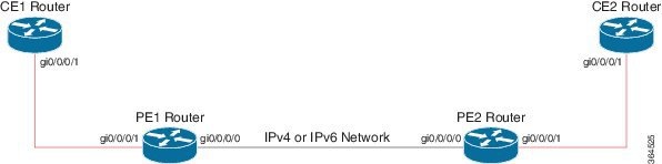
Figure 1. IP-in-IP tunnel network topology

A maximum of 3500 IP-in-IP tunnels are supported until Cisco IOS XR Release 25.4.1. From Cisco IOS XR Release 25.4.1, you can use the hw-module profile cef iptunnel scale command to configure up to 12,000 IP-in-IP tunnels that are shared between the gRIBI-based encapsulation and decapsulation next-hop tunnels. For more information, see Configure improved scale for IP-in-IP tunnels.


Restrictions for IP-in-IP tunnel configuration

Observe the following restrictions when you configure IP-in-IP tunnels:

  • The feature does not support decapsulation tunnels on subinterfaces.

  • Only the default Virtual Routing and Forwarding (VRF) instance is supported.

  • IPv6 link local addresses are not supported.

  • Regular tunnels cannot use a configured IP address as the tunnel source; only a non-existent IP address can be used.

  • Configuring multiple interfaces with the same IP address is not supported.

  • Each line card can have different number of Network Processor (NP) slices.

  • The maximum IPv4 and IPv6 IP-in-IP decapsulation tunnels supported is 64 per slice.

  • From Cisco IOS XR Release 25.3.1 onwards, the maximum IPv4 and IPv6 IP-in-IP decapsulation tunnels supported is 200 per slice.


Configure improved scale for IP-in-IP tunnels

Procedure

1.

Enter global configuration mode.

Example:

Router# configure
2.

Enter the hw-module profile cef iptunnel scale command to configure the maximum IP-in-IP tunnel scale to 12K for gRIBI-based encapsulation and decapsulation next-hops.

Example:


Router(config)# hw-module profile cef iptunnel scale
3.

Save the configuration and exit the configuration mode.

Example:


Router(config)# commit
Router(config)# exit
4.

Reload the line cards with the reload location all command to enable the increased IP-in-IP scale limit.

Example:

Router# reload location all
5.

Execute the show hw-module profile cef command to view the configuration status of CEF hardware modules.

Example:

Router# show hw-module profile cef

Fri Aug 22 13:23:17.796 UTC
--------------------------------------------------------------
Knob                          Status          Applied   Action
--------------------------------------------------------------
CBF Enable                    Unconfigured    N/A       None
CBF forward-class-list        Unconfigured    N/A       None
BGPLU                         Unconfigured    N/A       None
LPTS ACL                      Unconfigured    N/A       None
Dark Bandwidth                Unconfigured    N/A       None
SR-OPT                        Unconfigured    N/A       None
IP Redirect Punt              Unconfigured    N/A       None
IPv6 Hop-limit Punt           Unconfigured    N/A       None
MPLS Per Path Stats           Unconfigured    N/A       None
SRv6 Per Path Stats           Unconfigured    N/A       None
Tunnel TTL Decrement          Unconfigured    N/A       None
High-Scale No-LDP-Over-TE     Unconfigured    N/A       None
Label over TE counters        Unconfigured    N/A       None
Highscale LDPoTE No SRoTE     Unconfigured    N/A       None
LPTS Pifib Entry Counters     Unconfigured    N/A       None
Unipath surpf                 Unconfigured    N/A       None
Source-based rtbh             Unconfigured    N/A       None
Vxlan ipv6 tunnel scale       Unconfigured    N/A       None
Encap Exact                   Unconfigured    N/A       None
Iptunnel scale                Configured      Yes       None
BGPLU over RSVPTE Enable      Unconfigured    N/A       None
MPLS Decap Stats              Unconfigured    N/A       None

Configuration example for IPv4 tunnel

This example provides the configuration for an IPv4 tunnel.

Table 2. PE1 and PE2 router configuration

PE1 router configuration

PE2 router configuration

interface GigabitEthernet0/0/0/0
 !! Link between PE1-PE2
 ipv4 address 100.1.1.1/24
!
interface GigabitEthernet0/0/0/1
 !! Link between CE1-PE1
 ipv4 address 20.1.1.1/24
 ipv6 address 20::1/64
!
interface tunnel-ip 1
 ipv4 address 10.1.1.1/24
 ipv6 address 10::1/64
 tunnel mode ipv4
 tunnel source GigabitEthernet0/0/0/0
 tunnel destination 100.1.1.2
!
router static
 address-family ipv4 unicast
  30.1.1.0/24 tunnel-ip1
 address-family ipv6 unicast
  30::0/64 tunnel-ip1
 !
!
interface GigabitEthernet0/0/0/0
 !! Link between PE1-PE2
 ipv4 address 100.1.1.2/24
!
interface GigabitEthernet0/0/0/1
 !! Link between PE2-CE2
 ipv4 address 30.1.1.1/24
 ipv6 address 30::1/64
!
interface tunnel-ip 1
 ipv4 address 10.1.1.2/24
 ipv6 address 10::2/64
 tunnel mode ipv4
 tunnel source GigabitEthernet0/0/0/0
 tunnel destination 100.1.1.1
!
router static
 address-family ipv4 unicast
  20.1.1.0/24 tunnel-ip1
 address-family ipv6 unicast
  20::0/64 tunnel-ip1
 !
!
Table 3. CE1 and CE2 router configuration

CE1 router configuration

CE2 router configuration

interface GigabitEthernet0/0/0/1
 !! Link between CE1-PE1
 ipv4 address 20.1.1.2 255.255.255.0
 ipv6 address 20::2/64
!
router static
 address-family ipv4 unicast
  30.1.1.0/24 20.1.1.1
 address-family ipv6 unicast
  30::0/64 20::1
 !
!
interface GigabitEthernet0/0/0/1
 !! Link between CE2-PE2
 ipv4 address 30.1.1.2 255.255.255.0
 ipv6 address 30::2/64
!
router static
 address-family ipv4 unicast
  20.1.1.0/24 30.1.1.1
 address-family ipv6 unicast
  20::0/64 30::1
 !
!

Configuration example for IPv6 tunnel

This example provides the configuration for an IPv6 tunnel.

Table 4. PE1 and PE2 router configuration

PE1 router configuration

PE2 router configuration

interface GigabitEthernet0/0/0/0
 !! Link between PE1-PE2
 ipv6 address 100::1/64
!
interface GigabitEthernet0/0/0/1
 !! Link between CE1-PE1
 vrf RED
 ipv4 address 20.1.1.1/24
 ipv6 address 20::1/64
!
interface tunnel-ip 1
 vrf RED
 ipv4 address 10.1.1.1/24
 ipv6 address 10::1/64
 tunnel mode ipv6
 tunnel source GigabitEthernet0/0/0/0
 tunnel destination 100::2
!
vrf RED
 address-family ipv6 unicast
  import route-target
   2:1
  !
  export route-target
   2:1
  !
 address-family ipv4 unicast
  import route-target
   2:1
  !
  export route-target
   2:1
  !
router static
 vrf RED
  address-family ipv4 unicast
   30.1.1.0/24 tunnel-ip1
  address-family ipv6 unicast
   30::0/64 tunnel-ip1
  !
 !
!
interface GigabitEthernet0/0/0/0
 !! Link between PE1-PE2
 ipv6 address 100::2/64
!
interface GigabitEthernet0/0/0/1
 !! Link between PE2-CE2
 vrf RED
 ipv4 address 30.1.1.1/24
 ipv6 address 30::1/64
!
interface tunnel-ip 1
 vrf RED
 ipv4 address 10.1.1.2/24
 ipv6 address 10::2/64
 tunnel mode ipv6
 tunnel source GigabitEthernet0/0/0/0
 tunnel destination 100::1
!
vrf RED
 address-family ipv6 unicast
  import route-target
   2:1
  !
  export route-target
   2:1
  !
 address-family ipv4 unicast
  import route-target
   2:1
  !
  export route-target
   2:1
  !
router static
 vrf RED
  address-family ipv4 unicast
   20.1.1.0/24 tunnel-ip1
  address-family ipv6 unicast
   20::0/64 tunnel-ip1
  !
 !
!
Table 5. CE1 and CE2 router configuration

CE1 router configuration

CE2 router configuration

interface GigabitEthernet0/0/0/1
 !! Link between CE1-PE1
 ipv4 address 20.1.1.2 255.255.255.0
 ipv6 address 20::2/64
!
router static
 address-family ipv4 unicast
  30.1.1.0/24 20.1.1.1
 address-family ipv6 unicast
  30::0/64 20::1
 !
!
interface GigabitEthernet0/0/0/1
 !! Link between CE2-PE2
 ipv4 address 30.1.1.2 255.255.255.0
 ipv6 address 30::2/64
!
router static
 address-family ipv4 unicast
  20.1.1.0/24 30.1.1.1
 address-family ipv6 unicast
  20::0/64 30::1
 !
!