Interfaces and Hardware Component Configuration Guide for Cisco 8000 Series Routers, Cisco IOS XR Releases

PDF

Interfaces and Hardware Component Configuration Guide for Cisco 8000 Series Routers, Cisco IOS XR Releases

Ethernet CFM

Want to summarize with AI?

Log in

This topic describes Ethernet Connectivity Fault Management (CFM), a service-level OAM protocol that provides tools for monitoring and troubleshooting end-to-end Ethernet services per VLAN, including proactive connectivity monitoring, fault verification, and fault isolation using standard Ethernet frames across the entire end-to-end Ethernet network.


Ethernet Connectivity Fault Management (CFM) is a service-level OAM protocol that

  • provides tools for monitoring and troubleshooting end-to-end Ethernet services per VLAN

  • includes proactive connectivity monitoring, fault verification, and fault isolation, and

  • uses standard Ethernet frames and can be run on any physical media that is capable of transporting Ethernet service frames. Unlike most other Ethernet protocols which are restricted to a single physical link, CFM frames can transmit across the entire end-to-end Ethernet network.

Table 1. Feature History Table

Feature name

Release

Description

Y.1731 support on CFM

Release 26.1.1

Introduced in this release on: Centralized Systems (8400 [ASIC:K100]) )(select variants only*)

*This feature is now supported on Cisco 8404-SYS-D routers.

Up MEP and down MEP support in CFM

Release 26.1.1

Introduced in this release on: Centralized Systems (8400 [ASIC:K100]) )(select variants only*)

*This feature is now supported on Cisco 8404-SYS-D routers.

CFM on bundle member link for connectivity check

Release 26.1.1

Introduced in this release on: Centralized Systems (8400 [ASIC:K100]) )(select variants only*)

*This feature is now supported on Cisco 8404-SYS-D routers.

Monitoring Layer 3 connectivity using down MEP on L3 interfaces

Release 26.1.1

Introduced in this release on: Centralized Systems (8400 [ASIC:K100]) )(select variants only*)

*This feature is now supported on Cisco 8404-SYS-D routers.

Y.1731 support on CFM

Release 25.4.1

Introduced in this release on: Fixed Systems (8010 [ASIC: A100], 8700 [ASIC: K100])(select variants only*)

*This feature is supported on:

  • 8711-48Z-M

  • 8011-32Y8L2H2FH

  • 8011-12G12X4Y-A/D

Increase in number of CFM sessions

Release 25.4.1

Introduced in this release on: Fixed Systems (8010 [ASIC: A100])(select variants only*)

*This feature is now supported on:

  • 8011-32Y8L2H2FH

  • 8011-12G12X4Y-A/D

CFM on bundle member link for connectivity check

Release 25.4.1

Introduced in this release on: Fixed Systems (8010 [ASIC: A100], 8700 [ASIC: K100])(select variants only*)

*This feature is now supported on:

  • 8011-32Y8L2H2FH

  • 8011-12G12X4Y-A/D

  • 8711-48Z-M

Up MEP and down MEP support in CFM

Release 25.4.1

Introduced in this release on: Fixed Systems (8010 [ASIC: A100], 8700 [ASIC: K100])(select variants only*)

*This feature is now supported on:

  • 8011-32Y8L2H2FH

  • 8011-12G12X4Y-A/D

  • 8711-48Z-M

Monitoring Layer 3 connectivity using down MEP on L3 interfaces

Release 25.4.1

Introduced in this release on: Fixed Systems (8010 [ASIC: A100])(select variants only*)

*This feature is now supported on:

  • 8011-32Y8L2H2FH

  • 8011-12G12X4Y-A/D

Up MEP and down MEP support in CFM

Release 25.4.1

Introduced in this release on: Fixed Systems (8010 [ASIC: A100])(select variants only*)

*This feature is now supported on:

  • 8011-32Y8L2H2FH

  • 8011-12G12X4Y-A/D

Y.1731 support on CFM

Release 25.3.1

Introduced in this release on: Fixed Systems (8010 [ASIC: A100], 8700 [ASIC: P100])(select variants only*); Modular Systems (8800 [LC ASIC: P100])(select variants only*)

This feature is now supported on:

  • 8011-4G24Y4H-I

  • 8711-32FH-M

  • 88-LC1-52Y8H-EM

  • 88-LC1-12TH24FH-E

Increase in number of CFM sessions

Release 25.1.1

Introduced in this release on: Fixed Systems (8700 [ASIC: K100], 8010 [ASIC: A100])

This feature is now supported on:

  • 8712-MOD-M

  • 8011-4G24Y4H-I

CFM on bundle member link for connectivity check

Release 25.1.1

Introduced in this release on: Fixed Systems ( 8010 [ASIC: A100])

This feature is now supported on Cisco 8011-4G24Y4H-I routers.

Monitoring Layer 3 connectivity using down MEP on L3 interfaces

Release 25.1.1

Introduced in this release on: Fixed Systems ( 8010 [ASIC: A100]) (select variants only*)

*This feature is now supported on Cisco 8011-4G24Y4H-I routers.

Up MEP and down MEP support in CFM

Release 25.1.1

Introduced in this release on: Fixed Systems (8700 [ASIC: K100], 8010 [ASIC: A100])

This feature is now supported on:

  • 8712-MOD-M

  • 8011-4G24Y4H-I

Increase in number of CFM sessions

Release 24.4.1

Introduced in this release on: Fixed Systems(8200, 8700); Centralized Systems (8600); Modular Systems (8800 [LC ASIC: Q100, Q200, P100])

The number of supported Connectivity Fault Management (CFM) sessions is now increased to 500. This enhancement improves fault detection, network visibility, scalability, and troubleshooting, which are crucial for managing high-performance networks.

CFM on bundle member link for connectivity check

Release 24.4.1

Introduced in this release on: Fixed Systems (8700 [ASIC: K100]) (select variants only*)

This feature introduces support for Connectivity Fault Management (CFM) on bundle members.

* This feature is supported on Cisco 8712-MOD-M routers.

Up MEP and down MEP support in CFM

Release 24.4.1

Introduced in this release on: Fixed Systems (8200 [ASIC: P100], 8700 [ASIC: P100, K100])(select variants only*); Modular Systems (8800 [LC ASIC: P100])(select variants only*)

This feature introduces Maintenance End Points (MEP) entities that you can configure in a domain.

*This feature is now supported on:

  • 8212-48FH-M

  • 8711-32FH-M

  • 8712-MOD-M

  • 88-LC1-12TH24FH-E

  • 88-LC1-36EH

  • 88-LC1-52Y8H-EM

Monitoring Layer 3 connectivity using down MEP on L3 interfaces

Release 24.4.1

Introduced in this release on: Fixed Systems (8200 [ASIC: P100], 8700 [ASIC: P100, K100]) (select variants only*); Modular Systems (8800 [LC ASIC: P100])

This enhancement expands network diagnostics to L3 interfaces at L2 network termination, simplifying the management and maintenance of multilayer networks.

* This feature is supported on Cisco 8712-MOD-M routers.

Monitoring Layer 3 connectivity using down MEP on L3 interfaces

Release 24.2.1

This enhancement expands network diagnostics to L3 interfaces at L2 network termination, simplifying the management and maintenance of multilayer networks. Without impacting the underlying L2 infrastructure, this feature uses CFM packets to verify the connection of L3 paths.

Previously, CFM Down MEP support was limited to L2 interfaces associated with cross-connect or bundle members.

This feature is supported on both physical main and subinterfaces, bundle main and subinterfaces.

CFM on bundle member link for connectivity check

Release 7.3.15

This feature introduces support for Connectivity Fault Management (CFM) on bundle members. Earlier, network administrators managed networks by using the fault, configuration, account, performance, security model. CFM is one of a suite of the Ethernet OAM protocols, which uses a combination of keepalive packets and MAC-based pings, and traceroutes to detect faults in a network.

With the CFM feature, you:

  • reduce operating expenses for service operators by reducing network faults and errors

  • provide end-to-end maintenance of networks

Up MEP and down MEP support in CFM

Release 7.3.15

This feature introduces Maintenance End Points (MEP) entities that you can configure in a domain.

MEPs send either CFM frames from the interface where they are configured or CFM frames that are received on other interfaces.

MEPs allow you to perform fault management and carry out performance checks.

CFM is defined in these standards:

  • IEEE 802.1ag—Defines the core features of the CFM protocol.

  • ITU-T Y.1731—Redefines, but maintains compatibility with the features of IEEE 802.1ag, and defines some additional features.

Ethernet CFM supports these functions of ITU-T Y.1731:

  • ETH-CC, ETH-RDI, ETH-LB, ETH-LT—These are equivalent to the corresponding features defined in IEEE 802.1ag.

    Note

    The Linktrace responder procedures defined in IEEE 802.1ag are used rather than the procedures defined in Y.1731; however, these are interoperable.

  • ETH-AIS—The reception of ETH-LCK messages is also supported.


Configuration guidelines and restrictions for Ethernet CFM

Supported CCM interval timers and configurations

Configure the CCM interval timer within the supported values for the session type.

  • Supported timers for CFM sessions: 1s, 10s, 1m, 10m.

  • Supported timers for CFM sessions on bundle members: 100ms, 1s, 10s, 1m, 10m.

From Release 24.4.1, Cisco 8000 routers support 500 CFM sessions.

Unsupported CFM configurations

The following CFM configurations are not supported:

  • The system supports only cross-connect.

  • MIPs are not supported.

  • L3 Interfaces and sub-Interfaces

  • Bridge Domain, Release 7.3.1 and earlier

  • VPLS, Release 7.3.1 and earlier

  • L3 interfaces are not supported except for bundle members.

  • Down MEPs are only supported for L2 cross-connect and bundle members.

  • Multiple MEPs of different directions are not supported on the same interface or Xconnect.

  • CFM is not supported on L2 subinterfaces with default encapsulation.

Include the interface in an L2VPN when configuring CFM down MEP

When you configure a CFM down MEP on an interface, ensure that the interface is included in an L2VPN.

This principle applies when you configure a CFM down MEP on an interface.


Maintenance domains

The maintenance domain is a management space that

  • manages and administers a network

  • operates under a single entity, and

  • defines boundaries through specific bridge ports.

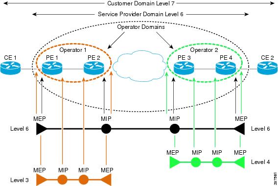
Figure 1. CFM Maintenance Domain

Administrators assign maintenance levels between 0 and 7 to define hierarchical relationships. Organizations use CFM maintenance domains in the following ways:

  • The customer uses CFM between CE devices to verify and manage connectivity across the entire network.

  • The service provider uses CFM between PE devices to verify and manage the services they provide.

  • Each operator uses CFM within their operator network to verify and manage connectivity within that network.

CFM maintenance domains allow different organizations to use CFM in the same network, but independently. For example, consider a service provider who offers a service to a customer, and to provide that service, they use two other operators in segments of the network. In this environment, CFM can be used in the following ways:

  • The customer can use CFM between their CE devices, to verify and manage connectivity across the whole network.

  • The service provider can use CFM between their PE devices, to verify and manage the services they are providing.

  • Each operator can use CFM within their operator network, to verify and manage connectivity within their network.

This figure shows an example of the different levels of maintenance domains in a network.

Note

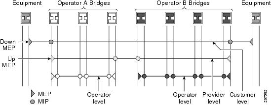
In CFM diagrams, the conventions are that triangles represent MEPs, pointing in the direction that the MEP sends CFM frames, and circles represent MIPs.

Figure 2. Different CFM Maintenance Domains Across a Network

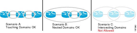
To ensure that the CFM frames for each domain do not interfere with each other, each domain is assigned a maintenance level, between 0 and 7. Where domains are nested, as in this example, the encompassing domain must have a higher level than the domain it encloses. In this case, the domain levels must be negotiated between the organizations involved. The maintenance level is carried in all CFM frames that relate to that domain.

CFM maintenance domains may touch or nest, but cannot intersect. This figure illustrates the supported structure for touching and nested domains, and the unsupported intersection of domains.


Configure a CFM maintenance domain

Use this procedure to configure a CFM maintenance domain.

Procedure

1.

Enter global configuration mode.

Example:

Router# configure
2.

Enter Ethernet Connectivity Fault Management (CFM) configuration mode.

Example:

Router(config)# ethernet cfm
3.

Use the domain domain-name level level-value [id [null] [dns DNS-name] [mac H.H.H] [string string] ] command to create, name a container for all domain configurations, and enter CFM domain configuration mode.

Example:

Router(config-cfm)# domain Domain_One level 1 id string D1

The level must be specified.

The id is the maintenance domain identifier (MDID) and is used as the first part of the maintenance association identifier (MAID) in CFM frames. If the MDID is not specified, the domain name is used as the MDID by default.

4.

(Optional) Use the traceroute cache hold-time minutes size entries command to set the maximum limit of traceroute cache entries or the maximum time limit to hold the traceroute cache entries.

Example:

Router(config-cfm)# traceroute cache hold-time 1 size 3000
The default is 100 minutes and 100 entries.
5.

Save the configuration changes to the running configuration file.

Example:

Router(config-cfm-dmn)# commit
6.

End the configuration session and exits to the EXEC mode.

Example:

Router(config-cfm-dmn)# end

Configure services for a CFM maintenance domain

To configure services for a CFM maintenance domain, perform the following steps:

Procedure

1.

Enter global configuration mode.

Example:

Router# configure
2.

Enter Ethernet Connectivity Fault Management (CFM) configuration mode.

Example:

Router(config)# ethernet cfm
3.

Use the domain domain-name level level-value [id [null] [dns DNS-name] [mac H.H.H] [string string] ] command to create, name a container for all domain configurations, and enter CFM domain configuration mode.

Example:

Router(config-cfm)# domain Domain_One level 1 id string D1

The id is the maintenance domain identifier (MDID) and is used as the first part of the maintenance association identifier (MAID) in CFM frames. If the MDID is not specified, the domain name is used as the MDID by default.

4.

Use the down-meps | xconnect group xconnect-group-name p2p xconnect-name}[id command to configure and associate a service with the domain and enters CFM domain service configuration mode. You can specify that the service is used only for down MEPs.

Example:

Router(config-cfm-dmn)# service xconnect group X1

The id sets the short MA name.

5.

Save the configuration changes to the running configuration file.

Example:

Router(config-cfm-dmn-svc)# commit
6.

End the configuration session and exits to the EXEC mode.

Example:

Router(config-cfm-dmn-svc)# end

Services

The CFM service is a partition of a maintenance domain that

  • organizes connectivity within the network

  • operates independently within specific network segments, and

  • aligns with the network topology to prevent frame leakage.

A CFM service allows an organization to partition its CFM maintenance domain, according to the connectivity within the network.

For example, if the network is divided into a number of virtual LANs (VLANs), a CFM service is created for each of these. CFM can then operate independently in each service. It is important that the CFM services match the network topology, so that CFM frames relating to one service cannot be received in a different service. For example, a service provider may use a separate CFM service for each of their customers, to verify and manage connectivity between that customer's end points.

Each CFM service operates within an associated maintenance domain and adopts that domain's maintenance level. All CFM frames relating to the service carry this maintenance level.

Organizations implement CFM services to manage network connectivity in these ways:

  • Organizations partition the maintenance domain according to network connectivity requirements.

  • Administrators create a unique service for each virtual LAN to ensure independent operation.

  • Service providers assign separate services to customers to verify and manage specific end-point connectivity.

Note

IEEE 802.1ag refers to CFM services as Maintenance Associations, while ITU-T Y.1731 refers to CFM services as Maintenance Entity Groups.


Maintenance points

A CFM Maintenance Point (MP) is an instance of a particular CFM service on a specific interface that

  • resides on a specific interface

  • processes CFM frames at the same maintenance level, and

  • enforces maintenance domain boundaries.

  • Maintenance End Points (MEPs)—Created at the edge of the domain. Maintenance end points (MEPs) are members of a particular service within a domain and are responsible for sourcing and sinking CFM frames. They periodically transmit continuity check messages and receive similar messages from other MEPs within their domain. They also transmit traceroute and loopback messages at the request of the administrator. MEPs are responsible for confining CFM messages within the domain.

A maintenance point is always associated with a particular CFM service, and therefore with a particular maintenance domain at a particular level. CFM maintenance points operate only on interfaces where they are configured; otherwise, the interface forwards CFM frames transparently. Maintenance points process frames at their associated maintenance level, forward frames at higher levels transparently, and drop frames at lower levels.

CFM maintenance points include the following types:

  • Maintenance End Points (MEPs) function at the edge of the domain.

  • MEPs belong to a specific service within a domain and source or sink CFM frames.

  • MEPs periodically transmit and receive continuity check messages to monitor connectivity.

  • MEPs transmit traceroute and loopback messages upon administrator request to confine CFM messages within the domain.


Maintenance End Points and Connectivity Fault Management processes

The Maintenance Endpoints (MEPs) are network elements that define the boundary of a domain at an interface rather than at a bridge or host. They are categorized into these types:

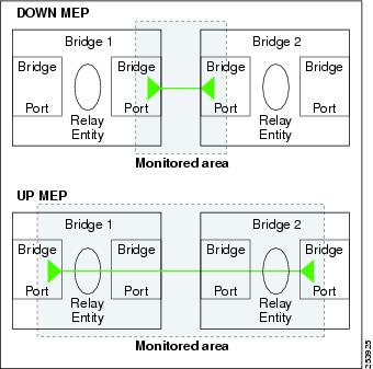
  • Down MEPs—The Down MEPs are endpoints that send Connectivity Fault Management (CFM) frames from the interface where they are configured, and process CFM frames received on that interface. They transmit Alarm Indication Signal (AIS) messages upward toward the cross-connect.

  • Up MEPs—The Up MEPs are endpoints that send frames into the bridge relay function as if they had been received on the interface where the MEP is configured. They process CFM frames received on other interfaces that have been switched through the bridge relay function as if they are going to be sent out of the interface where the MEP is configured. Up MEPs transmit AIS messages downward toward the wire. AIS packets are only sent when a Maintenance Intermediate Point (MIP) is configured on the same interface as the MEP and at the level of the MIP.

Characteristics and operational rules of MEPs

These instructions describe the characteristics and operational rules of MEPs:

  • The terms Down MEP and Up MEP are defined in the IEEE 802.1ag and ITU-T Y.1731 standards, and refer to the direction that CFM frames are sent from the MEP. The terms should not be confused with the operational status of the MEP.

  • The router supports only the configuration where the Down MEP level is less than the Up MEP level.

  • Up MEPs can only exist on switched (Layer 2) interfaces, because they send and receive frames from the bridge relay function. Down MEPs can be created on switched (Layer 2) interfaces.

  • MEPs continue to operate normally if the interface they are created on is blocked by the Spanning Tree Protocol (STP); that is, CFM frames at the level of the MEP continue to be sent and received, according to the direction of the MEP. MEPs never allow CFM frames at the level of the MEP to be forwarded, so the STP block is maintained.

  • A separate set of CFM maintenance levels is created every time a VLAN tag is pushed onto the frame. Therefore, if CFM frames are received on an interface which pushes an additional tag, so as to “tunnel” the frames over part of the network, the CFM frames will not be processed by any MPs within the tunnel, even if they are at the same level. For example, if a CFM MP is created on an interface with an encapsulation that matches a single VLAN tag, any CFM frames that are received at the interface that have two VLAN tags will be forwarded transparently, regardless of the CFM level.

This figure illustrates the monitored areas for Down and Up MEPs.

Figure 3. Monitored Areas for Down and Up MEPs

This figure shows maintenance points at different levels. Because domains are allowed to nest but not intersect, a MEP at a low level often corresponds with a MEP at a higher level.


Configure cross-check on a MEP for a CFM service

To configure cross-check on a MEP for a CFM service and specify the expected set of MEPs, complete the following steps:

Procedure

1.

Enter global configuration mode.

Example:

Router# configure
2.

Enter Ethernet Connectivity Fault Management (CFM) configuration mode.

Example:

Router(config)# ethernet cfm
3.

Use the domain domain-name level level-value [id [null] [dns DNS-name] [mac H.H.H] [string string] ] command to create, name a container for all domain configurations, and enter CFM domain configuration mode.

Example:

Router(config-cfm)# domain Domain_One level 1 id string D1

The level must be specified.

The id is the maintenance domain identifier (MDID) and is used as the first part of the maintenance association identifier (MAID) in CFM frames. If the MDID is not specified, the domain name is used as the MDID by default.

4.

Use the service service-name { down-meps | xconnect group xconnect-group-name p2p xconnect-name}[id [icc-based icc-string umc-string ] | [string text] | [number number] | [vlan-id id-number] | [vpn-id oui-vpnid]] command to configure and associate a service with the domain and enters CFM domain service configuration mode. You can specify that the service is used only for down MEPs, or associate the service with a xconnect where up MEPs will be created.

The id sets the short MA name.

5.

Enter CFM MEP crosscheck configuration mode.

Example:

Router# mep crosscheck mep-id 10
6.

Use the mep-id mep-id-number command to enable cross-check on a MEP.

Example:

Router(config-cfm-xcheck)# mep-id 10
Note
  • For non-offloaded and software-offloaded MEPs, use the mep-id mep-id-number [mac-address mac-address] command.

  • For hardware-offloaded MEPs, use the mep-id mep-id-number command. From Release 24.2.11, mac-address mac-address option is obsolete for hardware-offloaded MEPs.

  • Repeat this command for every MEP that you want included in the expected set of MEPs for cross-check.

7.

mep-id mep-id-number mep-id-number [mac-address mac-address]

Example:

Router(config-cfm-xcheck)# mep-id 10

Enables cross-check on a MEP.

Note
  • Repeat this command for every MEP that you want included in the expected set of MEPs for cross-check.

8.

Save the configuration changes to the running configuration file and remain within the configuration session.

Example:

Router(config-cfm-xcheck)# commit
9.

End the configuration session and exits to the EXEC mode.

Example:

Router(config-cfm-xcheck)# end

Configure other options for a CFM service

To configure other options for a CFM service, complete the following steps:

Procedure

1.

Enter global configuration mode.

Example:

Router# configure
2.

Enter Ethernet Connectivity Fault Management (CFM) configuration mode.

Example:

Router(config)# ethernet cfm
3.

Use the domain domain-name level level-value [id [null] [dns DNS-name] [mac H.H.H] [string string] ] command to create, name a container for all domain configurations, and enter CFM domain configuration mode.

Example:

Router(config-cfm)# domain Domain_One level 1 id string D1

The level must be specified.

The id is the maintenance domain identifier (MDID) and is used as the first part of the maintenance association identifier (MAID) in CFM frames. If the MDID is not specified, the domain name is used as the MDID by default.

4.

Use the service service-name { down-meps | xconnect group xconnect-group-name p2p xconnect-name}[id [icc-based icc-string umc-string ] | [string text] | [number number] | [vlan-id id-number] | [vpn-id oui-vpnid]] command to configure and associate a service with the domain and enters CFM domain service configuration mode. You can specify that the service is used only for down MEPs, or associate the service with a xconnect where up MEPs will be created.

The id sets the short MA name.

5.

(Optional) Use the maximum-meps number command to configure the maximum number (2 to 8190) of MEPs across the network, which limits the number of peer MEPs recorded in the database.

Example:

Router(config-cfm-dmn-svc)# maximum-meps 1000
6.

Use the log {ais|continuity-check errors|continuity-check mep changes|crosscheck errors|efd} command to enables logging of certain types of events.

Example:

Router(config-cfm-dmn-svc)# log continuity-check errors
7.

Save the configuration changes to the running configuration file and remain within the configuration session.

Example:

Router(config-cfm-dmn-svc)# commit
8.

End the configuration session and exits to the EXEC mode.

Example:

Router(config-cfm-dmn-svc)# end

Configure CFM MEPs

  • For every subinterface configured under a Layer 3 parent interface, you must associate a unique 802.1Q or 802.1ad tag. Else, it leads to unknown network behavior.

Procedure

1.

Enter global configuration mode.

Example:

Router# configure
2.

Specify the type of Ethernet interface on which you want to create a MEP. Enter HundredGigE or TenGigE and the physical interface or virtual interface.

Example:

Router(config)# interface TenGigE 0/0/0/1
Note
  • Use the show interfaces command to see a list of all interfaces currently configured on the router.

  • L3 interfaces are only supported for bundle member interfaces. Else, you must enable l2transport.

3.

Specify the type of Ethernet interface on which you want to create a MEP. Enter interface {HundredGigE | TenGigE | Bundle-Ether} interface-path-idl2transport and the physical interface or virtual interface followed by the l2transport. L2transport configures the interface as an L2 interface.

Example:

Router(config)# interface TenGigE 0/0/0/1

Naming convention is interface-path-id .subinterface . The period in front of the subinterface value is required as part of the notation.

4.

Enter interface Ethernet CFM configuration mode.

Example:

Router(config-if)# ethernet cfm
5.

Use the mep domain domain-name service service-name mep-id id-number command to create a maintenance end point (MEP) on an interface, and enter interface CFM MEP configuration mode.

Example:

Router(config-if-cfm)# mep domain Dm1 service Sv1 mep-id 1
6.

(Optional) Configure the class of service (CoS) (from 0 to 7) for all CFM packets generated by the MEP on an interface. If not configured, the CoS is inherited from the Ethernet interface.

Example:

Router(config-if-cfm-mep)# cos 7
Note

For Ethernet interfaces, the CoS is carried as a field in the VLAN tag. Therefore, CoS only applies to interfaces where packets are sent with VLAN tags. If the cos (CFM) command is executed for a MEP on an interface that does not have a VLAN encapsulation configured, it will be ignored.

7.

Save the configuration changes to the running configuration file and remain within the configuration session.

Example:

Router(config-if-cfm-mep)# commit
8.

End the configuration session and exits to the EXEC mode.

Example:

Router(config-if-cfm-mep)# end

CFM protocol messages

The CFM messages are protocol messages that

  • use the CFM EtherType and carry the CFM maintenance level for the domain to which they apply, and serve different purposes, and

  • are defined by IEEE 802.1ag and ITU-T Y.1731 standards.

These topics describe the CFM messages that are used to verify connectivity, isolate faults, and trace paths:

  • Continuity Check (IEEE 802.1ag and ITU Y.1731)

  • Loopback (IEEE 802.1ag and ITU Y.1731)

  • Linktrace (IEEE 802.1ag and ITU Y.1731)


Continuity Check (IEEE 802.1ag and ITU-T Y.1731)

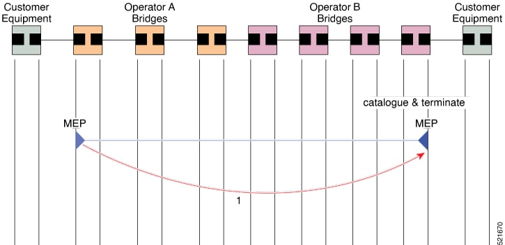
Continuity Check Messages (CCMs) are CFM protocol messages, also known as multicast heartbeat messages that are exchanged periodically between all Maintenance End Points (MEPs) in a service, allow each MEP to discover its peer MEPs, and verify connectivity between them.

The CCMs carry a variety of information that enables detection of different defects in the service, and they are transmitted at configurable intervals, and cataloged by Maintenance Intermediate Points (MIPs) at the same maintenance level.

Table 2. Feature History Table

Feature Name

Release Information

Feature Description

Continuity Check (IEEE 802.1ag and ITU-T Y.1731)

Release 25.3.1

Introduced in this release on: Fixed Systems (8010 [ASIC: A100], 8700 [ASIC: P100])(select variants only*); Modular Systems (8800 [LC ASIC: P100])(select variants only*)

This feature is now supported on:

  • 8011-4G24Y4H-I

  • 8711-32FH-M

  • 88-LC1-52Y8H-EM

  • 88-LC1-12TH24FH-E

Continuity Check (IEEE 802.1ag and ITU-T Y.1731)

Release 25.1.1

Introduced in this release on: Fixed Systems ( 8010 [ASIC: A100])

Maintenance Endpoints (MEPs) capable of supporting Ethernet OAM send Continuity Check Messages (CCMs) at regular intervals to verify connectivity. If one of them stops receiving CCMs from another endpoint, it infers that there is a connectivity issue or fault in the path.

This feature is now supported on:

  • 8011-4G24Y4H-I

MIPs also receive CCMs. MIPs use the information to build a MAC learning database that is used when responding to Linktrace. For more information about Linktrace, see Linktrace (IEEE 802.1ag and ITU-T Y.1731).

Figure 4. Continuity Check Message Flow

CCM messages carry a variety of information that allows different defects to be detected in the service. This information includes:

  • A configured numeric identifier for the MEP (the MEP ID). Each MEP in the service must be configured with a different MEP ID.

  • In a Remote Defect Indication (RDI), each MEP includes this in the CCMs it is sending, if it has detected a defect relating to the CCMs it is receiving. This notifies all the MEPs in the service that a defect has been detected somewhere in the service.

  • The interval at which CCMs are being transmitted.

  • The status of the interface where the MEP is operating, for example, whether the interface is up, down, STP blocked, and so on.

    Note

    The status of the interface (up/down) should not be confused with the direction of any MEPs on the interface (Up MEPs/Down MEPs).

Characteristics and operational rules of CCMs

These instructions describe the characteristics and operational rules of CCMs:

  • All the MEPs in a service must transmit CCMs at the same interval. IEEE 802.1ag defines the following possible intervals that can be used:

    • 100 ms (only supported on bundle members)

    • 1 s

    • 10 s

    • 1 minute

    • 10 minutes

  • A MEP detects a loss of connectivity with one of its peer MEPs when some number of CCMs are missed. This occurs when sufficient time has passed during which a certain number of CCMs were expected, given the CCM interval. This number is called the loss threshold, and is usually set to 3.

  • With the exception of bundle members, CFM is supported only on interfaces that have Layer 2 transport feature enabled.

  • CCMs include identifiers such as the Maintenance Domain Identifier (MDID) and the Short MA Name (SMAN), which together form the Maintenance Association Identifier (MAID) that must be configured identically on every MEP in the service.

MAID formats

These are restrictions on the type of MAID that are supported for sessions with time interval of less than 1 minute. The MAID supports two types of formats on offloaded MEPs:

  • No Domain Name Format

    • MD Name Format = 1-NoDomainName

    • Short MA Name Format = 3 - 2 bytes integer value

    • Short MA NAme Length = 2 - fixed length

    • Short MA Name = 2 bytes of integer

  • 1731 Maid Format

    • MD Name Format = 1-NoDomainName

    • MA Name Format(MEGID Format) = 32

    • MEGID Length = 13 - fixed length

    • MEGID(ICCCode) = 6 Bytes

    • MEGID(UMC) = 7 Bytes

    • ITU Carrier Code (ICC) - Number of different configurable ICC code - 15 (for each NPU)

    • Unique MEG ID Code (UMC) - 4

  • Maintenance Association Identifier (MAID) comprises of the Maintenance Domain Identifier (MDID) and Short MA Name (SMAN). MDID only supports null value and SMAN only supports ITU Carrier Code (ICC) or a numerical. No other values are supported.

    • An example for configuring domain ID null is: ethernet cfm domain SMB level 3 id null

    • An example for configuring SMAN is: ethernet cfm domain SMB level 3 id null service 901234AB xconnect group 99999 p2p 99999 id number 1

CCM defects

These defects can be detected from the received CCMs:

  • Interval mismatch: The CCM interval in the received CCM does not match the interval that the MEP is sending CCMs.

  • Level mismatch: A MEP has received a CCM carrying a lower maintenance level than the MEPs own level.

  • Loop: A CCM is received with the source MAC address equal to the MAC address of the interface where the MEP is operating.

  • Configuration error: A CCM is received with the same MEP ID as the MEP ID configured for the receiving MEP.

  • Cross-connect: A CCM is received with a MAID that does not match the locally configured MAID. This generally indicates a VLAN misconfiguration within the network, such that CCMs from one service are leaking into a different service.

  • Peer interface down: A CCM is received that indicates the interface on the peer is down.

  • Remote defect indication: A CCM is received carrying a remote defect indication.

    Note

    This defect does not cause the MEP to include a remote defect indication in the CCMs that it is sending.

Out-of-sequence CCMs can also be detected by monitoring the sequence number in the received CCMs from each peer MEP. However, this is not considered a CCM defect.

Restrictions on MEPs

These restrictions apply to MEPs:

  • Dynamic Remote MEPs are not supported for MEPs with less than 1 min interval. You must configure MEP CrossCheck for all such MEPs.

  • Sequence numbering is not supported for MEPs with less than 1 minute interval.

  • CCM Tx/Rx statistics counters are not supported for MEPs with less than1 minute intervals.

  • Sender TLV and Cisco Proprietary TLVs are not supported for MEPs with less than 1 minute intervals.


Configure continuity check for a CFM service

To configure Continuity Check for a CFM service, complete the following steps:

Procedure

1.

Enter global configuration mode.

Example:

Router# configure
2.

Enter Ethernet Connectivity Fault Management (CFM) configuration mode.

Example:

Router(config)# ethernet cfm
3.

Use the domain domain-name level level-value [id [null] [dns DNS-name] [mac H.H.H] [string string] ] command to create, name a container for all domain configurations, and enter CFM domain configuration mode.

Example:

Router(config-cfm)# domain Domain_One level 1 id string D1

The level must be specified.

The id is the maintenance domain identifier (MDID) and is used as the first part of the maintenance association identifier (MAID) in CFM frames. If the MDID is not specified, the domain name is used as the MDID by default.

4.

Use the down-meps | xconnect group xconnect-group-name p2p xconnect-name}[id command to configure and associate a service with the domain and enters CFM domain service configuration mode. You can specify that the service is used only for down MEPs.

Example:

Router(config-cfm-dmn)# service xconnect group X1

The id sets the short MA name.

5.

(Optional) Use the continuity-check interval time [loss-threshold threshold] command to enable Continuity Check and specify the time interval at which CCMs are transmitted or to set the threshold limit for when a MEP is declared down.

Example:

Router(config-cfm-dmn-svc)# continuity-check interval 100m loss-threshold 10
6.

(Optional) Use the continuity-check archive hold-time minutes command to configure how long information about peer MEPs is stored after they have timed out.

Example:

Router(config-cfm-dmn-svc)# continuity-check archive hold-time 100
7.

(Optional) Configure automatic triggering of a traceroute when a MEP is declared down.

Example:

Router(config-cfm-dmn-svc)# continuity-check loss auto-traceroute
8.

Save the configuration changes to the running configuration file and remain within the configuration session.

Example:

Router(config-cfm-dmn-svc)# commit
9.

End the configuration session and exits to the EXEC mode.

Example:

Router(config-cfm-dmn-svc)# end

Loopback (IEEE 802.1ag and ITU-T Y.1731)

Loopback Messages (LBM) and Loopback Replies (LBR) are CFM protocol messages that

  • verify connectivity between a local MEP and a particular remote MP, and

  • sends unicast LBMs to the remote MP when requested by an administrator.

Table 3. Feature History Table

Feature Name

Release Information

Feature Description

Loopback (IEEE 802.1ag and ITU-T Y.1731)

Release 25.3.1

Introduced in this release on: Fixed Systems (8010 [ASIC: A100], 8700 [ASIC: P100])(select variants only*); Modular Systems (8800 [LC ASIC: P100])(select variants only*)

This feature is now supported on

  • 8711-32FH-M

  • 88-LC1-52Y8H-EM

  • 88-LC1-12TH24FH-E

Loopback (IEEE 802.1ag and ITU-T Y.1731)

Release 25.1.1

Introduced in this release on: Fixed Systems ( 8010 [ASIC: A100])(select variants only*)

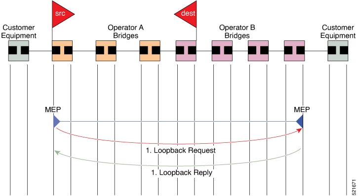
You can test connectivity between a local Maintenance End Point (MEP) and a remote Maintenance Point (MP) by sending Loopback Messages (LBM) and Loopback Replies (LBR). The connectivity verification facilitates effective network troubleshooting and maintenance without requiring a detailed hop-by-hop path analysis.

This feature is now supported on Cisco 8011-4G24Y4H-I routers.


How CFM loopback works

Loopback messages function similarly to an ICMP Echo (ping) and indicate destination reachability but do not allow hop-by-hop path discovery. This process enables administrators to verify connectivity between a local MEP and a remote maintenance point efficiently without detailed path analysis.

Loopback messages can be padded with user-specified data to detect data corruption and carry a sequence number to detect out-of-order frames.

Summary

The following actors and components participate in this process:

  • Originating MEP: Sends a unicast LBM to the target maintenance point.

  • Target maintenance point: Receives the LBM and sends an LBR back to the originating MEP.

  • Intermediate bridges: Forward the LBM like normal data traffic while respecting maintenance levels.

  • Bridge forwarding database: Determines the outgoing interface for the loopback message at each device.

Workflow

Figure 5. Loopback Messages

These stages describe how a CFM loopback message flows between a local MEP and the target maintenance point and enables administrators to verify connectivity between a local MEP and a remote maintenance point efficiently without detailed path analysis.

  1. On receiving each LBM, the target maintenance point sends an LBR back to the originating MEP.
  2. Loopback messages function similarly to an ICMP Echo (ping) and indicate destination reachability but do not allow hop-by-hop path discovery.
  3. Since loopback messages are destined for unicast addresses, they are forwarded like normal data traffic while respecting maintenance levels.
  4. At each device the loopback message reaches, if the outgoing interface is known in the bridge's forwarding database, the frame is sent out on that interface.
  5. If the outgoing interface is not known, the loopback message is flooded on all interfaces within the domain.

Linktrace (IEEE 802.1ag and ITU-T Y.1731)

Linktrace Messages (LTM) and Linktrace Replies (LTR) are CFM protocol messages that are used to track the path (hop-by-hop) to a unicast destination MAC address.

The linktrace mechanism is designed to provide useful information even after a network failure. This allows it to be used to locate failures, for example after a loss of continuity is detected. To achieve this, each MP maintains a CCM Learning Database. This maps the source MAC address for each received CCM to the interface through which the CCM was received. It is similar to a typical bridge MAC learning database, except that it is based only on CCMs and it times out much more slowly—on the order of days rather than minutes.

In IEEE 802.1ag, the CCM Learning Database is referred to as the MIP CCM Database. However, it applies to both MIPs and MEPs.

Table 4. Feature History Table

Feature Name

Release Information

Feature Description

Linktrace (IEEE 802.1ag and ITU-T Y.1731)

Release 25.4.1

Introduced in this release on: Fixed Systems (8010 [ASIC: A100])(select variants only*)

*This feature is now supported on:

  • 8011-32Y8L2H2FH

  • 8011-12G12X4Y-A/D

Linktrace (IEEE 802.1ag and ITU-T Y.1731)

Release 25.3.1

Introduced in this release on: Fixed Systems (8010 [ASIC: A100], 8700 [ASIC: P100])(select variants only*); Modular Systems (8800 [LC ASIC: P100])(select variants only*)

This feature is now supported on:

  • 8011-4G24Y4H-I

  • 8711-32FH-M

  • 88-LC1-52Y8H-EM

  • 88-LC1-12TH24FH-E

Linktrace (IEEE 802.1ag and ITU-T Y.1731)

Release 25.1.1

Introduced in this release on: Fixed Systems ( 8010 [ASIC: A100])(select variants only*)

You can trace the path to a specific unicast destination MAC address on a network using the Linktrace Messages (LTM) and Linktrace Replies (LTR) diagnostic tools. These tools perform a detailed hop-by-hop path analysis to identify connectivity problems.

This feature is now supported on:

  • 8011-4G24Y4H-I


How linktrace works

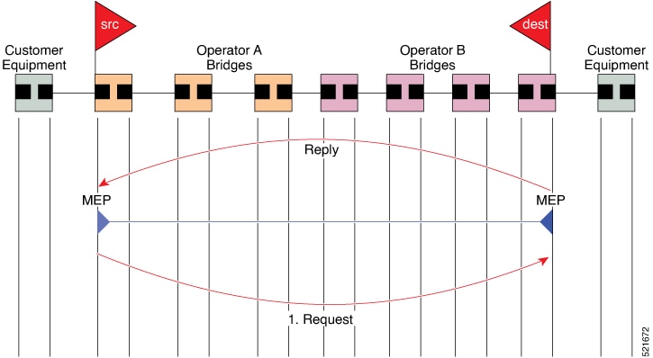
CFM linktrace is similar in concept to IP traceroute, although the mechanism is different. In IP traceroute, successive probes are sent, whereas CFM linktrace uses a single LTM that is forwarded by each MP in the path. LTMs are multicast and carry the unicast target MAC address as data within the frame. They are intercepted at each hop where there is a maintenance point, and either retransmitted or dropped to discover the unicast path to the target MAC address.

Note

IEEE 802.1ag and ITU-T Y.1731 define slightly different linktrace mechanisms. In particular, the use of the CCM learning database and the algorithm described here for responding to LTM messages are specific to IEEE 802.1ag. IEEE 802.1ag also specifies additional information that can be included in LTRs. Regardless of the differences, the two mechanisms are interoperable.

Summary

The following actors and components participate in this process:

  • Operator: Requests a linktrace operation from the local MEP.

  • Originating MEP: Sends a multicast LTM that carries the unicast target MAC address, and collects the LTRs returned by maintenance points along the path.

  • Intermediate maintenance points (MPs): Intercept the LTM, consult their forwarding tables to decide whether to reply, and either send an LTR back to the originating MEP or drop the LTM.

  • Bridge MAC learning table: The first table an MP consults to look up the target MAC address.

  • CCM learning database: The second table an MP consults when the target MAC address is not in the bridge MAC learning table.

Workflow

Figure 6. Linktrace Message Flow

These stages describe how a CFM linktrace operation discovers the path to a target MAC address:

  1. Stage 1 — The operator triggers the linktrace. At the request of the operator, the local MEP sends an LTM. The LTM is multicast and carries the unicast target MAC address as data within the frame.
  2. Stage 2 — Each MP intercepts the LTM and decides whether to reply. In IEEE 802.1ag, when an MP receives an LTM message, it determines whether to send a reply using these steps:
    • The target MAC address in the LTM is looked up in the bridge MAC learning table. If the MAC address is known, and therefore the egress interface is known, then an LTR is sent.
    • If the MAC address is not found in the bridge MAC learning table, then it is looked up in the CCM learning database. If it is found, then an LTR is sent.
    • If the MAC address is not found, then no LTR is sent, and the LTM is not forwarded.
  3. Stage 3 — The originating MEP collects the replies. Each MP that finds the target MAC address sends an LTR back to the originating MEP, which enables the administrator to discover connectivity data about the path. If the target MAC has never been seen previously in the network, the linktrace operation does not produce any results.

Configurable logging

CFM supports logging of various conditions to syslog. Logging can be enabled independently for each service, and when the following conditions occur:

  • New peer MEPs are detected, or loss of continuity with a peer MEP occurs.

  • Changes to the CCM defect conditions are detected.

  • Cross-check "missing" or "unexpected" conditions are detected.

  • AIS condition detected (AIS messages received) or cleared (AIS messages no longer received).

  • EFD used to shut down an interface, or bring it back up.


CFM hardware offload

Depending on where the continuity check messages (CCMs) are processed, offload is categorized into these types:

  • Software offload—When CCMs are processed by the line card CPU, offload type is known as software offload. Software offload is supported only on bundle interface.

  • Hardware offload—When CCMs are processed by network processing unit (NPU), offload type is known as hardware offload.

  • Non-offload—When CCMs are processed by route processor (RP), offload type is known as non-offload.

Table 5. Feature History Table

Feature Name

Release Information

Feature Description

CFM hardware offload

Release 26.2.1

Introduced in this release on: Modular Systems (8400 [ASIC: K100])(select variants only*)

This feature enables faster fault detection in Connectivity Fault Management (CFM) sessions.

It introduces hardware offload capabilities for 1 ms CCM interval, where the NPU now directly processes these packets.

*This feature is supported on Cisco 8404-SYS-D.

CFM hardware offload

Release 25.4.1

Introduced in this release on: Fixed Systems (8010 [ASIC: A100], 8700 [ASIC: K100])(select variants only*)

*This feature is supported on:

  • 8711-48Z-M

  • 8011-32Y8L2H2FH

  • 8011-12G12X4Y-A/D

CFM hardware offload

Release 25.3.1

Introduced in this release on: Fixed Systems (8010 [ASIC: A100]) (select variants only*)

This feature enables faster fault detection in Connectivity Fault Management (CFM) sessions.

It introduces hardware offload capabilities for 3.3 ms, 10 ms, and 100 ms CCM intervals, where the NPU now directly processes these packets.

*This feature is supported on 8011-4G24Y4H-I.

CCM intervals are the intervals in which CCMs are sent and received. If the CCMs are not received within the configured interval, the CFM MEP goes down. The following table shows the supported CCM timers for the offload types:

Interface Type

Offload Type

Supported CCM Timers

Physical interfaces and subinterfaces

Non-offload

  • 1 sec

  • 10 sec

  • 1 min

  • 10 min

Hardware offload

  • 1 sec

  • 3.3 ms

  • 10 ms

  • 100 ms

Bundle members

Non-offload

  • 1 sec

  • 10 sec

  • 1 min

  • 10 min

Hardware offload

  • 1 sec

  • 3.3 ms

  • 10 ms

  • 100 ms

Bundle interfaces and subinterfaces

Non-offload

  • 1 sec

  • 10 sec

  • 1 min

  • 10 min

Hardware offload

  • 1 sec

  • 3.3 ms

  • 10 ms

  • 100 ms