Interfaces and Hardware Component Configuration Guide for Cisco 8000 Series Routers, Cisco IOS XR Releases

PDF

Interfaces and Hardware Component Configuration Guide for Cisco 8000 Series Routers, Cisco IOS XR Releases

Integrated Routing and Bridging

Want to summarize with AI?

Log in

This topic describes how Integrated Routing and Bridging (IRB) provides the ability to route between a bridge group and a routed interface.


The Integrated Routing and Bridging (IRB) is a networking feature that

  • routes traffic between bridge groups and routed interfaces

  • utilizes Bridge-Group Virtual Interfaces (BVI) for connectivity, representing the link between the bridging and the routing domains on the router, and

  • supports receipt of packets from a bridged interface that are destined to a routed interface by configuring BVI with the appropriate IP addresses and relevant Layer 3 attributes.

The IRB provides the ability to route traffic between a bridge group and a routed interface through a BVI. A BVI functions as a virtual interface within the router and acts like a standard routed interface. This interface links the bridging and routing domains by associating with a single bridge domain. To support the receipt of packets from a bridged interface that are destined for a routed interface, the system configures the BVI with the appropriate IP addresses and relevant Layer 3 attributes. While previous software releases required physical cabling to connect the egress Layer 2 bridge domain to a Layer 3 routing domain, Cisco IOS XR Release 4.0.1 and later versions accomplish this functionality using the BVI configuration.

The BVI configuration requires these implementation steps:

  • The network administrator associates the BVI with a single bridge domain.

  • The system assigns the appropriate IP addresses and Layer 3 attributes to the BVI.

  • The router enables the BVI to act as the primary link between the bridging and routing domains.
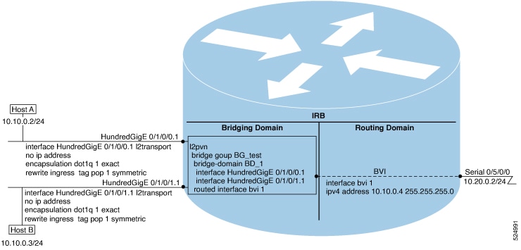
Figure 1. IRB Functional View and Configuration Elements

Bridge-Group Virtual Interface

The Bridge-Group Virtual Interface (BVI) is a virtual interface that

  • acts as a gateway between a bridge domain and a routed interface

  • supports Layer 3 attributes, and

  • utilizes a configurable MAC address.

BVI functions as a virtual interface within the router and provides a gateway for the corresponding bridge domain to a routed interface. While it does not support bridging itself, it maintains specific operational characteristics:

  • Uses a MAC address taken from the local chassis MAC address pool, unless overridden at the BVI interface.

  • Is configured as an interface type using the interface BVI command and uses an IPv4 address that is in the same subnet as the hosts on the segments of the bridged domain. The BVI also supports secondary addresses.

  • The BVI identifier is independent of the bridge-domain identifier. These identifiers do not need to correlate like they do in Cisco IOS software.

  • Is associated to a bridge group using the routed interface BVI command.

  • BVI interfaces support a number range of 1 to 4294967295.


Supported features on BVI

The following are the supported features on BVI:

  • Border Gateway Protocol (BGP)

  • Bidirectional Forwarding Detection (BFD)

  • Open Shortest Path First (OSPF)

  • Integrated Intermediate System-to-Intermediate System (IS-IS)

  • Netflow

  • Access Control Lists

These interface commands are supported on a BVI:

  • arp purge-delay

  • arp timeout

  • bandwidth (The default is 10 Gbps and is used as the cost metric for routing protocols for the BVI)

  • ipv4

  • ipv6

  • mac-address

  • mtu (The default is 1500 bytes)

  • shutdown

  • The BVI supports IP helper addressing and secondary IP addressing.


BVI MAC address

By default, the Cisco 8000 Series Router uses one MAC address for all BVI interfaces on the router. However, this means that the MAC address is not unique globally. If you want to override the default and specify a unique MAC address at the BVI, then you can configure it at the BVI interface.


BVI interface and line protocol states

Like typical interface states on the router, a BVI has both an Interface and Line Protocol state.

  • The BVI interface state is Up when these instances occur:

    • The BVI interface is created.

    • The bridge-domain that is configured with the routed interface bvi command has at least one available active bridge port (Attachment circuit [AC] or pseudowire [PW]).

      Note

      A BVI will be moved to the Down state if all of the bridge ports (Ethernet flow points [EFPs]) associated with the bridge domain for that BVI are down. However, the BVI will remain up if at least one pseudowire is up, even if all EFPs are down.

  • The following characteristics determine when the the BVI line protocol state is up:

    • The bridge-domain is in Up state.

    • The BVI IP address is not in conflict with any other IP address on another active interface in the router.


Packet flows using IRB

The IRB packet flow is a networking process that

  • resolves ARP requests between hosts and the BVI

  • directs traffic between bridged and routed interfaces, and

  • manages packet forwarding through the bridge or routing engines.

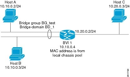
This figure shows a simplified functional diagram of an IRB implementation to describe different packet flows between Host A, B, and C. In this example, Host C is on a network with a connection to the same router. In reality, another router could be between Host C and the router shown.

Figure 2. IRB packet flows between hosts

The router performs these processing steps when IRB is configured:

  • ARP requests are resolved between the hosts and BVI that are part of the bridge domain.

  • All packets from a host on a bridged interface go to the BVI if the destination MAC address matches the BVI MAC address. Otherwise, the packets are bridged.

  • For packets destined for a host on a routed network, the BVI forwards the packets to the routing engine before sending them out a routed interface.

  • All packets either from or destined to a host on a bridged interface go to the BVI first (unless the packet is destined for a host on the bridge domain).

  • For packets that are destined for a host on a segment in the bridge domain that come in to the router on a routed interface, the BVI forwards the packet to the bridging engine, which forwards it through the appropriate bridged interface.


Packet flows when host A sends to host B on the bridge domain

When host A sends data to host B in the bridge domain on the 10.10.0.0 network, no routing occurs. The hosts are on the same subnet and the packets are bridged between their segment interfaces on the router.


Packet flows when host A sends to host C from the bridge domain to a routed interface

Using host information from this figure, the following occurs when host A sends data to host C from the IRB bridging domain to the routing domain:

  • Host A sends the packet to the BVI (as long any ARP request the is resolved between the host and the BVI). The packet has the following information:

    • Source MAC address of host A.

    • Destination MAC address of the BVI.

  • Since host C is on another network and needs to be routed, the BVI forwards the packet to the routed interface with the following information:

    • IP source MAC address of host A (10.10.0.2) is changed to the MAC address of the BVI (10.10.0.4).

    • IP destination address is the IP address of host C (10.20.0.3).

  • Interface 10.20.0.2 sees receipt of a packet from the routed BVI 10.10.0.4. The packet is then routed through interface 10.20.0.2 to host C.


Packet flows when host C sends to host B from a routed interface to the bridge domain

Using host information from this figure, the following occurs when host C sends data to host B from the IRB routing domain to the bridging domain:

  • The packet comes into the routing domain with the following information:

    • MAC source address—MAC of host C.

    • MAC destination address—MAC of the 10.20.0.2 ingress interface.

    • IP source address—IP address of host C (10.20.0.3).

    • IP destination address—IP address of host B (10.10.0.3).

  • When interface 10.20.0.2 receives the packet, it looks in the routing table and determines that the packet needs to be forwarded to the BVI at 10.10.0.4.

  • The routing engine captures the packet that is destined for the BVI and forwards it to the BVI’s corresponding bridge domain. The packet is then bridged through the appropriate interface if the destination MAC address for host B appears in the bridging table, or is flooded on all interfaces in the bridge group if the address is not in the bridging table.


Supported environments for IRB

These environments and configuration elements are supported with IRB on the Cisco 8000 Series Router:

  • Configuration of one BVI per bridge domain.

  • Virtual Private LAN Service (VPLS) virtual forwarding instance (VFI) configuration associated with a bridge domain configured with a BVI.

  • BGP PIC edge for BVI-based prefixes.

  • Traffic forwarding for the BVI using Open Shortest Path First (OSPF), Intermediate System-to-Intermediate System (IS-IS), and Border Gateway Protocol (BGP).

  • Internet Group Management Protocol (IGMP) static groups.

  • Dynamic Host Configuration Protocol (DHCP) relay agent. When DHCP relay is used from an aggregation node to obtain an IP address, the default gateway will be the IP address configured on the BVI. The BVI IP address should be in a common subnet as the DHCP pool that is being used by the aggregation node to assign IP addresses.

  • Virtual Router Redundancy Protocol (VRRP) configuration and priority.

  • Hot Standby Router Protocol (HSRP).

  • Up to 255 VRRP or HSRP virtual MAC addresses can be configured on a physical or bundle interface, with each VRRP or HSRP ID assigned to only one BVI interface.

  • Bridging of non-IP packets on a bridge domain configured with a BVI.

  • Parity with stateful protocol support as currently supported on Layer 3 subinterfaces on the Cisco 8000 Series Router.

  • IP SLA support as currently supported on Layer 3 subinterfaces on the Cisco 8000 Series Router.

  • Load balancing of BVIs as ECMP paths (up to 32 paths).

  • Interface-MIB.

  • Packet counters for BVI interfaces.


Additional IPv4-specific environments supported for IRB

  • Layer 3 IP multicast, with ability to take ingress IP multicast traffic and bridge it to multiple Layer 2 subinterfaces (Ethernet flow points) on a bridge domain that are part of multicast groups.

  • VRFs for IPv4 (Per-VPN label VRFs only—not per prefix).


Additional IPv6-specific environments supported for IRB

Cisco IPv6 Provider Edge Router over MPLS (6PE) and IPv6 VPN Provider Edge (6VPE) support with BVI interfaces at the customer edge (CE)-facing side of the Cisco 8000 Series Router as the PE device with the following restriction:

Only per-VRF label allocation is supported (using the label-allocation-mode per-vrf command). For a configuration example, see the 6PE or 6VPE with BVI configuration: example.