Interfaces and Hardware Component Configuration Guide for Cisco 8000 Series Routers, Cisco IOS XR Releases

PDF

Interfaces and Hardware Component Configuration Guide for Cisco 8000 Series Routers, Cisco IOS XR Releases

IP-in-IP decapsulation

Want to summarize with AI?

Log in

This topic describes IP-in-IP decapsulation on the Cisco 8000 Series Router, which removes the outer IP header of an encapsulated packet so that the router can direct the packet to the next hop through the network.


IP-in-IP encapsulation involves the insertion of an outer IP header over the existing IP header. The source and destination addresses in the outer IP header point to the endpoints of the IP-in-IP tunnel. The stack of IP headers is used to direct the packet over a predetermined path to the destination, provided that the network administrator knows the loopback addresses of the routers transporting the packet. This tunneling mechanism can be used for determining availability and latency for most network architectures. The entire path from source to destination does not have to be included in the headers; a segment of the network can be chosen for directing the packets.

In IP-in-IP encapsulation and decapsulation, there are two types of packets. The original IP packets that are encapsulated are called inner packets, and the IP header stack added during encapsulation is called the outer packet.

The router supports only decapsulation, not encapsulation. Encapsulation is performed by remote routers.

Starting with Cisco IOS XR Release 7.3.5, the routers can handle multistack for-us packets within IP-in-IP tunnels efficiently. The for-us packets refer to IP packets with the source and destination terminating on the same router. Such packets are multistack when they undergo multiple layers of IP header encapsulation at ingress, loopback, and egress interfaces. With this improvement, your routers can identify IP packets with multistack tunneling IP header encapsulations and perform multiple IP header terminations on these packets. This capability enables you to configure IP packets to travel from the source endpoint to the destination endpoint and then back to the source, facilitating streamlined fault identification and isolation processes.

Table 1. Feature History Table

Feature Name

Release Information

Description

IP header decapsulation for multistack packet in IP-in-IP tunnels

Release 7.3.5

Your routers are now enhanced to identify IP packets with multistack IP header encapsulations and perform multiple IP header decapsulations on these packets. With this ability, you can use IP packets to travel from the source endpoint to the destination endpoint and then back to the source in an IP-in-IP tunnel. This feature facilitates identification of IP packets and streamlines fault identification and isolation processes in your IP-in-IP network.

This feature is enabled by default and does not require any configuration changes.


Topology for IP-in-IP decapsulation

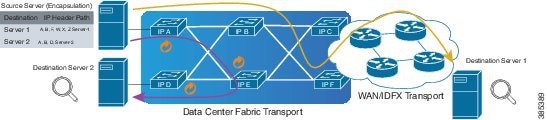
The following topology describes a use case where IP-in-IP encapsulation and decapsulation are used for different segments of the network from source to destination. The IP-in-IP tunnel consists of multiple routers that are used to decapsulate and direct the packet through the data center fabric network.

Figure 1. IP-in-IP decapsulation through a data center network

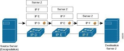
The following illustration shows how the stacked IPv4 headers are decapsulated as they traverse through the decapsulating routers.

Figure 2. IP header decapsulation

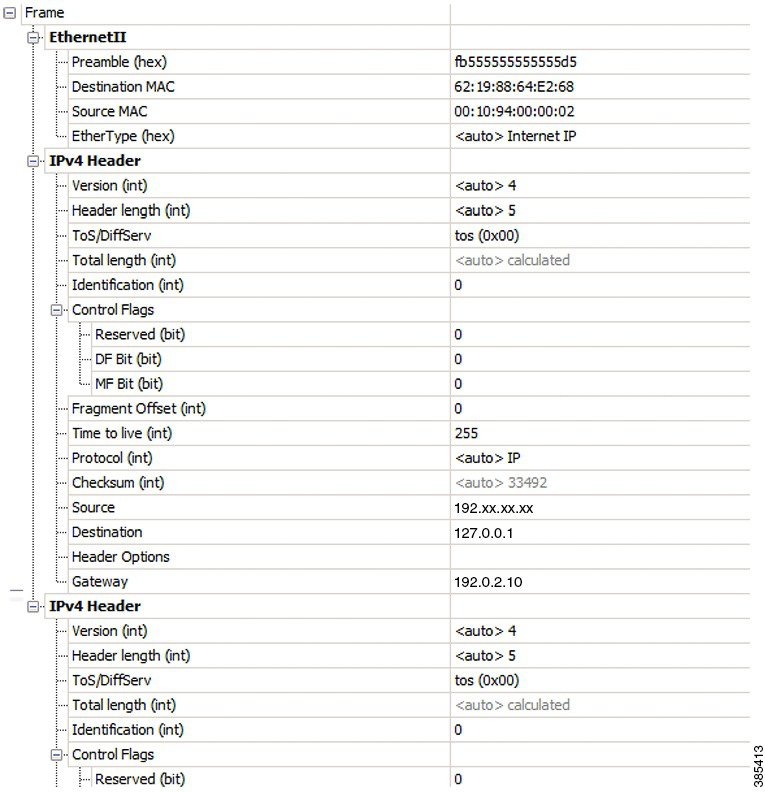
The encapsulated packet has an outer IPv4 header that is stacked over the original IPv4 header, as shown in the following illustration.

Figure 3. Encapsulated packet

Decapsulate packets in IP-in-IP tunnel

Use this procedure to decapsulate the packet as it traverses the IP-in-IP tunnel.

Procedure

1.

Enter the interface configuration mode for the loopback interface and assign an IPv4 address.

Example:

Router(config)# interface loopback 0
Router(config-if)# ipv4 address 127.0.0.1/32
Router(config-if)# no shutdown
Note

You can configure the tunnel destination only if you want to decapsulate packets from a particular destination. If no tunnel destination is configured, then all the IP-in-IP ingress packets on the configured interface are decapsulated.

2.

Create the tunnel interface using the tunnel-ip keyword.

Example:

Router(config-if)# interface tunnel-ip 10
3.

Configure the interface to process IPv4 packets without an explicit address by referencing the loopback interface.

Example:

Router(config-if)# ipv4 unnumbered loopback 1
4.

Set the tunnel mode for decapsulation. Specify that the tunnel interface performs IP-in-IP decapsulation.

Example:


Router(config-if)# tunnel mode ipv4 decap
5.

Define the tunnel source. Specify the source address for the decapsulation tunnel.

Example:

Router(config-if)# tunnel source loopback 0
6.

Apply an extended ACL that matches on the outer header for IP-in-IP decapsulation.

Example:

Router# show running-config interface bundle-Ether 50.5
Tue May 26 12:11:49.017 UTC
interface Bundle-Ether50.5
ipv4 address 101.1.5.1 255.255.255.0
encapsulation dot1q 5
ipv4 access-group ExtACL_IPinIP ingress
ipv4 access-group any_dscpegg egress
!
Router# show access-lists ipv4 ExtACL_IPinIP hardware ingress location$
Tue May 26 12:11:55.940 UTC
ipv4 access-list ExtACL_IPinIP
10 permit ipv4 192.168.0.0 0.0.255.255 any ttl gt 150
11 deny ipv4 172.16.0.0 0.0.255.255 any fragments
12 permit ipv4 any any

Starting with Cisco IOS XR Software Release 7.0.14, extended ACL must match on the outer header for IP-in-IP decapsulation. Extended ACL support reduces mirrored traffic throughput. This match is based only on the IPv4 protocol, and extended ACL is applied to the received outermost IP header, even if the outer header is locally terminated.


Decapsulation using tunnel source direct

To debug faults in various large networks, you might have to capture and analyze the network traffic at a packet level. In data center networks, administrators face problems with the volume of traffic and the diversity of faults. To troubleshoot faults in a timely manner, data center network administrators must identify affected packets inside large volumes of traffic. They must track them across multiple network components, analyze traffic traces for fault patterns, and test or confirm potential causes.

In some networks, IP-in-IP decapsulation is used in network management to verify ECMP availability and to measure the latency of each path within a data center.

You can perform these actions to manage network traffic using IP-in-IP decapsulation:

  • The Network Management System (NMS) sends IP-in-IP (IPv4 or IPv6) packets with a stack of predefined IPv4 or IPv6 headers (device IP addresses).

  • The destination device removes the outer header at each hop.

  • The device performs a lookup on the next header in the stack.

  • The device forwards the packet if a valid route exists.

  • Select specific ECMP links for troubleshooting by using the tunnel source direct command.

  • Using the tunnel source direct command, you can choose specific IP Equal-Cost Multipath (ECMP) links for troubleshooting when there are multiple IP links between two devices.

  • You can programmatically configure and manage the Ethernet interfaces using the openconfig-ethernet-if.yang and openconfig-interfaces.yang OpenConfig data models.

Table 2. Feature History Table

Feature Name

Release Information

Feature Description

Decapsulation using tunnel source direct

Release 26.1.1

Introduced in this release on: Centralized Systems (8400 [ASIC:K100]) )(select variants only*)

*This feature is now supported on Cisco 8404-SYS-D routers.

Decapsulation using tunnel source direct

Release 25.4.1

Introduced in this release on: Fixed Systems (8700 [ASIC: K100], 8010 [ASIC: A100])(select variants only*)

*This feature is supported on:

  • 8711-48Z-M

  • 8011-32Y8L2H2FH

  • 8011-12G12X4Y-A/D

Decapsulation using tunnel source direct

Release 25.1.1

Introduced in this release on: Fixed Systems (8010 [ASIC: A100])(select variants only*)

*This feature is supported on Cisco 8011-4G24Y4H-I routers.

Decapsulation using tunnel source direct

Release 24.4.1

Introduced in this release on: Fixed Systems (8200 [ASIC: P100], 8700 [ASIC: P100, K100])(select variants only*); Modular Systems (8800 [LC ASIC: P100])(select variants only*)

*This feature is now supported on:

  • 8212-48FH-M

  • 8711-32FH-M

  • 8712-MOD-M

  • 88-LC1-12TH24FH-E

  • 88-LC1-36EH

  • 88-LC1-52Y8H-EM

Decapsulation using tunnel source direct

Release 7.5.3

Tunnel source direct allows you to decapsulate the tunnels on any Layer 3 interface on the router.

You can use the tunnel source direct configuration command to choose the specific IP Equal-Cost Multipath (ECMP) links for troubleshooting, when there are multiple IP links between two devices.


Guidelines and limitations for decapsulation using tunnel source direct

The following guidelines apply to decapsulation using tunnel source direct:

  • The tunnel source direct command is only compatible with tunnel mode decap for IP-in-IP decapsulation.

  • The source-direct tunnel is always operationally up unless it is administratively shut down. The directly connected interfaces are identified using the show ip route direct command.

  • All Layer 3 interfaces that are configured on the device are supported.

  • The platform can accept and program only a certain number of IP addresses. The number of IP addresses depends on the make of the platform line card (LC). Each LC can have a different number of Network Processor (NP) slices and interfaces.

  • Only one source-direct tunnel per address family is supported for configuration.

  • Regular decapsulation tunnels that have a specific source address are supported. However, the tunnel's specific source address must not be part of any interface.

The following functionalities are not supported for the tunnel source direct option:

  • GRE tunneling mode.

  • VRF (only default VRF is supported).

  • ACL and QoS on the tunnels.

  • Tunnel encapsulation.

  • Tunnel NetIO DLL: Decapsulation is not supported if the packet is punted to slow path.


Configure decapsulation using tunnel source direct

Procedure

1.

Enter global configuration mode.

Example:

Router# configure terminal
2.

Configure IP-in-IP tunnel decapsulation on directly connected IPv4 addresses with the tunnel mode ipv4 decap and tunnel source direct commands.

Example:

Router(config)# interface Tunnel4
Router(config-if)# tunnel mode ipv4 decap
Router(config-if)# tunnel source direct
Router(config-if)# no shutdown
3.

Alternatively, configure IP-in-IP tunnel decapsulation on IPv6-enabled networks with the tunnel mode ipv6 decap and tunnel source direct commands.

Example:

Router(config)# interface Tunnel6
Router(config-if)# tunnel mode ipv6 decap
Router(config-if)# tunnel source direct
Router(config-if)# no shutdown
4.

Verify the configuration with the show running-config interface and show interface commands.

Example:

Router# show running-config interface tunnel 1
interface Tunnel1
  tunnel mode ipv6ipv6 decapsulate-any
  tunnel source direct
  no shutdown

Router# show interface tunnel 1
Tunnel1 is up    Admin State: up
MTU 1460 bytes, BW 9 Kbit
Tunnel protocol/transport IPv6/DECAPANY/IPv6
Tunnel source - direct
Tx    0 packets output, 0 bytes    Rx    0 packets input, 0 bytes

Tunnel destination with an object group

In IP-in-IP decapsulation, the router accepts a packet on a tunneled interface only when the tunnel IP address matches the source IP address of the incoming packets. With this implementation, you need to configure separate interface tunnels for each IP address for which the router receives traffic packets. This limitation often leads to configuration overload on the router.

You can eliminate the configuration overload on the router by assigning an object group as the tunnel destination for IPv4 and IPv6 traffic types. The router matches the source IP address of the incoming packet against the object group available as the tunnel destination. The decapsulation tunnel accepts the incoming traffic packets when there is a match between the packet source and the object group. Otherwise, the router drops the packets.

Table 3. Feature History Table

Feature Name

Release Information

Description

Configure tunnel destination with an object group

Release 7.5.4

You can now assign an object group as the destination for an IP-in-IP decapsulation tunnel. With this functionality, you can configure an IPv4 or IPv6 object group consisting of multiple IPv4 or IPv6 addresses as the destination for the tunnel instead of a single IPv4 or IPv6 address. Using an object group instead of a singular IP address helps reduce the configuration complexity on the router by replacing the multiple tunnels with one destination with a single decapsulation tunnel that supports a diverse range of destinations.

The feature introduces these changes:

  • CLI: New tunnel destination command.

  • YANG Data Model: New object-group option supported in the Cisco-IOS-XR-um-if-tunnel-cfg.yang Cisco native model.


Restrictions for tunnel destination with an object group

These restrictions apply to the tunnel destination with an object group feature:

  • GRE tunnels do not support configuring object groups as the tunnel destination.

  • The router supports configuring tunnel destination with an object group only when the tunnel source is tunnel source direct .

  • You can configure the object group as tunnel destination only on the default VRF.

  • Configuring object groups as the tunnel destination is not applicable to tunnel encapsulation.

  • Subinterfaces do not support configuring object groups as the tunnel destination.

  • Configuring object groups as the tunnel destination is mutually exclusive with ACL and QoS features.

  • The tunnel destination feature supports only IPv4 and IPv6 object groups.

  • The router does not support changing tunnel configuration after its creation. Configure the tunnel source direct and tunnel destination with an object group when creating the tunnel.


Configure tunnel destination with an object group

Before you begin

Procedure

1.

Enter global configuration mode.

Example:

Router# configure
2.

Create an IPv4 network object group.

Example:

Router(config)# object-group network ipv4 Test_IPv4
This command creates a new object group called Test_IPv4 for IPv4 network addresses and enters the object-group configuration mode.
3.

Add network address to the object group.

Example:

Router(config-object-group-ipv4)# 192.0.2.0/24
Router(config-object-group-ipv4)# 198.51.100.0/24
Router(config-object-group-ipv4)# 203.0.113.0/24
This adds the IPv4 subnets 192.0.2.0 with a 24-bit prefix length, 198.51.100.0/24, and 203.0.113.0/24 to the object group.
4.

Save the configuration and exit the object-group configuration mode.

Example:

Router(config-object-group-ipv4)# commit
Router(config-object-group-ipv4)# exit
5.

Enter the tunnel interface configuration mode.

Example:

Router(config)# interface tunnel-ip 1
6.

Set the tunnel mode to IPv4 decapsulation.

Example:

Router(config-if)# tunnel mode ipv4 decap
7.

Configure the tunnel source as direct, so the tunnel accepts all packets with a destination address matching the IP addresses on the router.

Example:

Router(config-if)# tunnel source direct
8.

Configure the tunnel destination as the defined IPv4 object group.

Example:


Router(config-if)# tunnel destination object-group ipv4 Test_IPv4
9.

Enable the tunnel interface, save the configuration and exit the configuration mode.

Example:

Router(config-if)# no shutdown
Router(config-if)# commit
Router(config-if)# exit
Configure the IPv6 tunnel destination with an object group. Follow the same steps as Define an IPv6 object group with the network elements that must be accepted by the decapsulation tunnel, enter the tunnel configuration mode, set the tunnel mode to IPv6 decap, configure the tunnel source as direct so that the tunnel accepts all packets with a destination address matching the IP addresses on the router, and configure the destination of the tunnel as the defined object group.
Router# configure
Router(config)# object-group network ipv6 Test_IPv6
Router(config-object-group-ipv6)# 2001:DB8::/32
Router(config-object-group-ipv6)# 2001:DB8::/48
Router(config-object-group-ipv6)# commit
Router(config-object-group-ipv6)# exit
Router(config)# interface tunnel-ip 2
Router(config-if)# tunnel mode ipv6 decap
Router(config-if)# tunnel source direct
Router(config-if)# tunnel destination object-group ipv6 Test_IPv6
Router(config-if)# no shutdown
Router(config-if)# commit
Router(config-if)# exit