Validated Profile: IT-Enabled Services (SD-Access) Vertical
Available Languages
Bias-Free Language
The documentation set for this product strives to use bias-free language. For the purposes of this documentation set, bias-free is defined as language that does not imply discrimination based on age, disability, gender, racial identity, ethnic identity, sexual orientation, socioeconomic status, and intersectionality. Exceptions may be present in the documentation due to language that is hardcoded in the user interfaces of the product software, language used based on RFP documentation, or language that is used by a referenced third-party product. Learn more about how Cisco is using Inclusive Language.
- US/Canada 800-553-2447
- Worldwide Support Phone Numbers
- All Tools
 Feedback
 Feedback
Information technology-enabled services (ITES) organizations are companies that provide numerous IT services, such as customer support, technical help desks, software development, and data processing. ITES organizations leverage technology to deliver these services, often over digital networks like the internet. ITES companies are an integral part of the global outsourcing industry, offering cost-effective solutions to businesses around the world. They are known for their ability to provide high-quality services, often at a lower cost compared to in-house operations in developed countries. These organizations play a crucial role in driving innovation, improving efficiency, and enabling businesses to focus on their core competencies.
The Cisco Validated Profile document offers guidance on navigating challenges, solutions, deployment options, operational management, and migration within an ITES profile network deployment. It encapsulates validated end-to-end use cases, scalability insights, and hardware and software recommendations to facilitate optimal decision-making during network and organizational deployment processes. Additionally, this document directs readers to associated design and deployment guides for enterprise networks, furnishing valuable insights into deploying common implementations of Cisco Software-Defined Access (SD‑Access).
Scope
This guide serves as a roadmap for understanding ITES network challenges, common use cases, and how Cisco SD-Access can address them. Although this guide doesn't provide in-depth configuration steps, it equips you with valuable insights for your ITES network strategy.
Traditional network versus Cisco SD-Access
This section provides an overview of the key differences between traditional network and Cisco SD‑Access.
Traditional Networks:
● Traditional networks require network devices to be configured manually.
● They often require a separate overlay network for segmentation.
● Security policies are typically enforced at network boundaries.
● Scaling the network can be complex and time-consuming.
● Troubleshooting is often reactive and requires manual intervention.
● Limited visibility into network traffic and application performance.
Cisco SD-Access:
● SD-Access automates network provisioning and management through policy-based automation.
● It simplifies network design by carrying Security Group Tag (SGT) information in the Virtual Extensible LAN (VXLAN) overlay while using a single underlay network for both connectivity and segmentation.
● Security policies are applied dynamically based on user and device identity.
● SD-Access scales more easily through automation and centralized control.
● Troubleshooting is proactive with network-wide visibility and analytics.
● SD-Access provides detailed insights into network traffic and application performance.
In summary, Cisco SD-Access offers a more streamlined and flexible approach compared to traditional networks, with centralized management, improved scalability, and enhanced security features.
Challenges in traditional networks
Today there are many challenges in managing the network, because of manual configuration and fragmented tool offerings. Manual operations are slow and error prone. Issues are exacerbated because of a constantly changing environment. The growth of users and different device types makes it more complex to configure and maintain a consistent user policy across the network.
● Network deployment challenges:
Setup or deployment of a single network switch can take several hours due to scheduling requirements and the need to work with different infrastructure groups. In some cases, deploying a batch of switches can take several weeks.
● Network security challenges:
Security is a critical component of managing modern networks. Organizations need to protect resources and make changes efficiently in response to real-time needs. In traditional networks, it can be challenging to track VLANs, Access Control Lists (ACLs), and IP addresses to ensure optimal policy and security compliance.
● Wireless and wired network challenges:
Disparate networks are common in many organizations, because different systems are managed by different departments. Typically, the main IT network is operated separately from building management systems, security systems, and other production systems. This leads to duplication of network hardware procurement and inconsistency in management practices.
● Network operations challenges:
IT teams often contend with outdated change management tools, difficulty in maintaining productivity, and slow issue resolution.
Advantages of Cisco SD-Access
Cisco SD-Access is designed to address the demands of rapid digitization. The core philosophy of the Cisco SD-Access architecture revolves around policy-based automation, enabling secure user and device segmentation across both wired and wireless connectivity.
Automation and simplicity boost productivity, allowing IT staff to innovate quickly and lead the industry in digital transformation, thereby enhancing operational effectiveness. A consistent segmentation framework aligned with business policies, regardless of transport medium (wired or wireless), is crucial for core effectiveness.
Cisco SD-Access provides these technological advantages:
● Simplified operations:
Simplifies network operations by providing a single, intuitive interface for managing the entire infrastructure, reducing complexity and operational overhead.
● Automation:
Automates routine network operations such as configuration, provisioning, and management. This reduces the risk of human error and increases efficiency. Catalyst Center streamlines the deployment, minimizing the need for interaction with Command Line Interfaces (CLI).
● Agility:
Network operations become more agile and align with business requirements by minimizing manual configuration steps.
● Security:
Provides enhanced security and segmentation through Virtual Networks (VNs) and SGTs. SD-Access provides a strong framework for securing and managing complex enterprise networks through macrosegmentation with VNs, and microsegmentation with SGTs.
● Consistent policies for wired and wireless:
Extends segmentation, visibility, and policy from wired to wireless networks. Distributed wireless termination scales network throughput while centralizing management and troubleshooting.
● Support for business analytics:
Aggregates analytics and telemetry information into a single platform, aiding business decisions and facilitating growth or diversification planning.
IT enabled services network overview
For guidance and recommendations on constructing a new greenfield deployment of the Cisco SD-Access fabric tailored to the challenges and use cases of an ITES network, proceed to the next sections to go deeper into the SD-Access fabric components. Learn about the benefits that Cisco SD-Access solutions offer in addressing the requirements and challenges specific to the ITES sector.
You can manage traditional networks using Cisco Prime Infrastructure or Catalyst Center. Catalyst Center provides automation, monitoring, and telemetry capabilities for both traditional networks and SD-Access environments. If you are managing a network with Cisco Prime Infrastructure and plan to migrate to Catalyst Center, refer to Cisco Prime Infrastructure to Cisco Catalyst Center Migration.
To migrate existing Cisco Catalyst legacy networks to a Cisco SD-Access fabric, refer to Migration to Cisco SD-Access, which explains options to migrate existing networks with wired and wireless endpoints.
SD-Access components
Cisco Catalyst Center
Catalyst Center (formerly known as Cisco DNA Center) is a centralized network management and orchestration platform designed to simplify network operations and management. It provides a single dashboard to manage and monitor your network infrastructure, including switches, routers, and wireless access points (AP)s.
Using Catalyst Center, network administrators can do tasks, including:
● Automate network provisioning:
Easily deploy network devices and services using automated workflows, reducing the time and effort required for configuration.
● Monitor network health:
Gain visibility into the entire network, including device status, traffic patterns, and performance metrics, to quickly identify and resolve issues.
● Implement security policies:
Define and enforce security policies across the network, ensuring compliance and protecting against threats.
● Manage software updates:
Simplify the process of updating device software and firmware, ensuring that network devices are up to date with the latest features and security patches.
● Troubleshoot network problems:
Use built-in tools and analytics to diagnose and resolve network issues quickly, minimizing downtime and disruption.
Overall, Catalyst Center helps organizations streamline network operations, improve efficiency, and enhance security, making it an essential tool for managing modern network infrastructures. The Catalyst Center platform is available in various form factors, including physical and virtual appliances. For details, refer to these resources:
● Cisco Catalyst Center Data Sheet (for supported platform and scale)
● Cisco Catalyst Center Installation Guide
Cisco Identity Service Engine
Cisco Identity Services Engine (ISE) is a security policy management and control platform. It automates and simplifies access control and security compliance for wired, wireless, and VPN connectivity. Cisco ISEoffers secure access to network resources, enforces security policies, and delivers comprehensive visibility into network access.
The key features of Cisco ISE include:
● Policy-based access control:
Define and enforce policies based on user roles, device types, and other contextual information.
● Authentication and authorization:
Support for various authentication methods (for example, 802.1X, MAB, web authentication) and enables dynamic authorization based on changing conditions.
● Endpoint compliance:
Assess the compliance of endpoints with security policies and enforce remediation actions, if necessary.
● Guest access:
Provide secure guest access to the network with customizable guest portals and sponsor approval workflows.
● Bring Your Own Device (BYOD) support:
Enable secure BYOD initiatives with device onboarding and policy enforcement.
● Integration and ecosystem:
Integrate with other security and networking technologies through APIs and partner ecosystem.
● Visibility and reporting:
Gain insights into network access and security posture through comprehensive reporting and analytics.
Cisco ISE is a critical component of Cisco's security and network access control portfolio, providing organizations with a centralized and scalable solution to address their security and access control needs. ISE supports both standalone and distributed deployment models. Multiple distributed nodes can be deployed collectively to enhance failover resiliency and scalability. For SD‑Access single-site deployments, it is recommended to have a basic two-node ISE deployment, with each ISE node running all services (or functions or roles) for redundancy.
For more information, refer to:
● Cisco Identity Services Engine Administrator Guide.
● Performance and Scalability Guide for Cisco Identity Services Engine.
Cisco Catalyst 9000 series switches
Cisco Catalyst 9000 series switching offers more flexible and highly scalable design options. Switches supported in different fabric roles offer secure, fast, and reliable connectivity to users and endpoints within the network.
For the data sheet, refer to Cisco Catalyst 9000 Series.
Cisco Catalyst Wireless LAN Controller and Access Point
Cisco Catalyst 9800 Series Wireless Controllers and Access Points (AP) provide seamless network management of and deployment on both on-premises and cloud for wireless clients.
For the data sheets for Catalyst 9800 and Catalyst 9100 devices refer to:
● Cisco Access Point and Wireless Controller Selector
Cisco SD-Access Fabric
Cisco SD-Access Fabric is a networking architecture that uses software-defined networking (SDN) concepts to automate network provisioning, segmentation, and policy enforcement. It aims to simplify network operations, enhance security, and improve user experience in modern digital workplaces.
Key components and features of Cisco SD-Access Fabric include:
● Network segmentation:
Divides the network into virtual segments based on user and device identity, enabling granular control over access and security policies.
● Centralized policy management:
Policies are defined centrally and enforced consistently across the entire network, reducing the risk of misconfiguration and policy conflicts.
● Automation:
Automates network provisioning, configuration, and management tasks, reducing manual errors and increasing operational efficiency.
● ISE:
Provides authentication and authorization services, ensuring that only authorized users and devices can access the network.
● Catalyst Center:
Serves as the management and orchestration platform for SD-Access, providing a single pane of glass for network management and troubleshooting.
● Scalability:
Supports large-scale deployments, enabling organizations to easily scale their networks as their needs expand.
● Enhanced security:
Improves network security by dynamically segmenting the network and enforcing security policies based on user and device identity.
Overall, Cisco SD-Access Fabric aims to simplify network management, improve security, and enhance scalability, making it an attractive option for organizations looking to modernize their network infrastructure.
Fabric architecture overview
Cisco SD-Access Fabric architecture is designed to simplify network operations, enhance security, and improve user experiences. It is based on the principles of SDN and incorporates various components to achieve these goals:
● Underlay network:
The physical network infrastructure that provides basic connectivity between devices. It typically consists of switches, routers, and cables.
● Overlay network:
A logical network built on top of the underlay network that provides virtualized connectivity between devices. It enables network segmentation and policy enforcement without the need for physical reconfiguration.
● Control plane:
Manages the overall operation of the network, including routing, forwarding, and policy enforcement. It is typically implemented using a centralized controller, such as Catalyst Center.
● Data plane:
Handles the actual forwarding of data packets within the network. It is implemented on network devices, such as switches and routers, and operates based on the instructions provided by the control plane.
● Policy plane:
Defines and enforces network policies, such as access control and segmentation. It ensures that network resources are used efficiently and securely.
● Management plane:
Provides tools and interfaces for managing and monitoring the network. It includes features such as configuration management, monitoring, and troubleshooting.
Overall, Cisco SD-Access Fabric architecture offers a comprehensive solution for modernizing network infrastructure, providing scalability, security, and automation capabilities to meet the evolving needs of digital businesses.
Network architecture
Fabric technology supports the SD-Access architecture on campus, enabling the use of VNs (overlay networks) running on a physical network (underlay network) to create alternative topologies for connecting devices. In SD-Access, the user-defined overlay networks are provisioned as virtual routing and forwarding (VRF) instances that provide separation of routing tables.
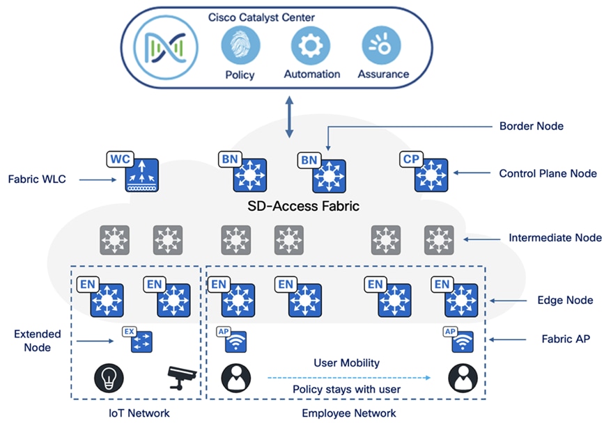
Fabric roles
A fabric role is an SD-Access software construct running on physical hardware. These software constructs are designed with modularity and flexibility in mind. For example, a device can run either a single role or multiple roles. Care should be taken to provision SD-Access fabric roles in alignment with the underlying network architecture, ensuring a distributed function approach. Separating roles across different devices provides the highest level of availability, resilience, deterministic convergence, and scalability.
The SD-Access fabric includes these roles:
● Control plane node
● Border node
● Edge node
● Intermediate node
● Fabric wireless controllers
● Fabric-mode APs
● Fabric in a box
● Extended nodes
Control plane node
SD-Access fabric control plane node combines LISP map-server and map-resolver functionalities on a single node. It maintains a database that tracks all endpoints within the fabric site, mapping them to fabric nodes. This design separates an endpoint’s IP or MAC address from its physical location (nearest router), ensuring efficient network operations.
Key functions of the control plane node:
● Host Tracking Database (HTDB):
Acts as a central repository for EID-to-RLOC bindings, where the RLOC is the Loopback 0 IP address of a fabric node. It functions similarly to a traditional LISP site, storing endpoint registrations.
● Endpoint Identifier (EID):
Identifies endpoint devices using MAC, IPv4, or IPv6 addresses in the SD-Access network.
● Map server:
Receives endpoint registrations, associates them with their corresponding RLOCs, and updates the HTDB accordingly.
● Map resolver:
Responds to queries from fabric devices, providing EID-to-RLOC mappings from the HTDB. This allows devices to determine the appropriate fabric node for forwarding traffic.
Border node
SD-Access fabric border node serves as the gateway between a fabric site and external networks, handling network virtualization interworking and the propagation of SGTs beyond the fabric.
Key functions of border nodes:
● EID subnet advertisement:
Uses Border Gateway Protocol (BGP) to advertise endpoint prefixes outside the fabric, ensuring return traffic is directed correctly.
● Fabric site exit point:
Functions as the default gateway for edge nodes using LISP PxTR (Proxy Tunnel Router). Internal border nodes can register known subnets with the control plane node.
● Network virtualization extension:
Extends segmentation beyond the fabric using VRF-lite and VRF-aware routing protocols.
● Policy mapping:
Maintains SGT information outside the fabric through SGT Exchange Protocol (SXP) or inline tagging in Cisco metadata.
● VXLAN encapsulation and de-encapsulation:
Converts external traffic into VXLAN for the fabric and removes VXLAN for outgoing traffic, acting as a bridge between the fabric and non-fabric networks.
Edge node
SD-Access fabric edge nodes function like access layer switches in a traditional campus LAN. They operate based on ingress and egress tunnel routers (xTR) in LISP and must be deployed using a Layer 3 routed access design. These edge nodes do several key functions:
● Endpoint registration:
Each edge node maintains a LISP control plane session with all control plane nodes. When an endpoint is detected, it is added to a local database called the EID-table. The edge node then sends a LISP map-register message to update the control plane’s HTDB (Host Tracking Database).
● Anycast Layer 3 gateway:
All edge nodes sharing the same EID subnet use a common IP and MAC address for seamless mobility and optimal forwarding. The anycast gateway is implemented as a Switched Virtual Interface (SVI) with a uniform MAC address across all edge nodes in the fabric.
● Layer 2 bridging:
Edge nodes handle Layer 2 traffic for endpoints within the same VLAN. They determine whether to bridge or route packets and use VXLAN Layer 2 VNIs (equivalent to VLANs) to bridge traffic to the correct destination. If traffic needs to exit the fabric, a Layer 2 border node is used.
● User-to-VN mapping:
Endpoints are assigned to VNs by associating them with VLANs linked to an SVI and VRF. This mapping ensures fabric segmentation at both the Layer 2 and Layer 3 LISP VNIs, even at the control plane level.
● AAA authentication:
Edge nodes can statically or dynamically assign endpoints to VLANs using 802.1X authentication. Acting as a Network Access Device (NAD), they collect authentication credentials, send them to an authentication server, and enforce access policies.
● VXLAN encapsulation and de-encapsulation:
When an edge node receives traffic from an endpoint (directly connected, via an extended node, or through an AP), it encapsulates it in VXLAN and forwards it across the fabric. Depending on the destination, the traffic is sent to another edge node or a border node. When encapsulated traffic arrives at an edge node, it is de-encapsulated and delivered to the endpoint. This mechanism enables endpoint mobility, allowing devices to move between edge nodes without changing their IP addresses.
Intermediate node
Intermediate nodes are part of the Layer 3 network used for interconnections among devices operating in fabric roles, such as the connections between border nodes and edge nodes. These interconnections are established in the global routing table on the devices and are collectively known as the underlay network. For example, in a three-tier campus deployment where the core switches are provisioned as border nodes and the access switches as edge nodes, the distribution switches function as the intermediate nodes.
Intermediate nodes do not require VXLAN encapsulation, de-encapsulation, LISP control plane messaging, or SGT awareness. Their primary function is to provide IP reachability and physical connectivity, while also supporting the increased MTU to accommodate larger IP packets encapsulated with fabric VXLAN information. Essentially, intermediate nodes route and transport IP traffic between devices operating in fabric roles.
Fabric wireless controllers
Both fabric wireless controllers and nonfabric wireless controllers provide AP image and configuration management, client session management, and mobility services. Fabric wireless controllers offer additional services for fabric integration, such as registering MAC addresses of wireless clients into the HTDB of the fabric control plane nodes during wireless client join events and supplying fabric edge node RLOC‑association updates to the HTDB during client roam events. Fabric integration with a wireless controller occurs on a per-SSID basis. Fabric-enabled SSID traffic is tunneled by the AP using VXLAN encapsulation to the fabric edge node, while centrally switched SSID traffic is tunneled by the AP using the Control and Provisioning of Wireless Access Points (CAPWAP) protocol to the wireless controllers. Thus, the wireless controller can operate in a hybrid or mixed mode, where some SSIDs are fabric-enabled while others are centrally switched.
● Traditional vs. SD-Access data handling:
In a traditional Cisco unified wireless network or nonfabric deployment, both control traffic and data traffic are tunneled back to the wireless controller using CAPWAP. From a CAPWAP control plane perspective, AP management traffic is generally lightweight, while client data traffic is the larger bandwidth consumer. Wireless standards have enabled progressively larger data rates for wireless clients, resulting in more client data being tunneled to the wireless controller. This requires a larger wireless controller with multiple high-bandwidth interfaces to support the increase in client traffic. In nonfabric wireless deployments, wired and wireless traffic have different enforcement points in the network. The wireless controller addresses quality of service and security when bridging the wireless traffic onto the wired network. For wired traffic, enforcement occurs at the first-hop access layer switch. This paradigm shifts entirely with SD-Access wireless. In SD-Access wireless, the CAPWAP tunnels between the wireless controllers and APs are used only for control traffic. Data traffic from wireless endpoints is tunneled to the first-hop fabric edge node, where security and policy can be applied in the same manner as for wired traffic.
● Network connectivity and wireless controller placement:
Typically, fabric wireless controllers connect to a shared services network through a distribution block or data center network that is located outside the fabric and fabric border, with the wireless controller management IP address existing in the global routing table. For wireless APs to establish a CAPWAP tunnel for wireless controller management, the APs must be in a VN with access to this external device. This means that the APs are deployed in the global routing table, and the wireless controller’s management subnet or specific prefix must be present in the Global Routing Table (GRT) within the fabric site. In the SD-Access solution, Cisco Catalyst Center configures wireless APs to reside within an overlay VN named INFRA_VN, which maps to the global routing table. This setup eliminates the need for route leaking or fusion routing (a multi-VRF device selectively sharing routing information) to establish connectivity between the wireless controllers and the APs. Each fabric site must have a wireless controller unique to that site. Most deployments place the wireless controller within the local fabric site itself, rather than across a WAN, due to latency requirements for local mode APs.
● Latency requirements and deployment considerations:
Fabric APs operate in local mode, which requires a Round-Trip Time (RTT) of 20 ms or less between the AP and the wireless controller. This typically means that the wireless controller is deployed in the same physical site as the APs. However, if this latency requirement is met through dedicated dark fiber or other very low-latency circuits between physical sites, and the wireless controllers are deployed physically elsewhere, such as in a centralized data center, the wireless controllers and APs can be in different physical locations. This deployment type, where fabric APs are located separately from their fabric wireless controllers, is commonly used in metro area networks and SD-Access for Distributed Campus environments. APs should not be deployed over WAN or other high-latency circuits from their wireless controllers in an SD-Access network. Maintaining a maximum RTT of 20 ms between these devices is crucial for performance.
Fabric-mode APs
Fabric-mode APs are Cisco Wi-Fi 7 (802.11be), Wi-Fi 6 (802.11ax) and 802.11ac Wave 2 APs associated with the fabric wireless controller that have been configured with one or more fabric-enabled SSIDs. These fabric-mode APs continue to support the same wireless media services as traditional APs, such as applying Application Visibility and Control (AVC), Quality of Service (QoS), and other wireless policies. Fabric APs establish a CAPWAP control plane tunnel to the fabric wireless controller and join as local-mode APs. They must be directly connected to the fabric edge node or extended node switch within the fabric site. For their data plane, fabric APs establish a VXLAN tunnel to their first-hop fabric edge switch, where wireless client traffic is terminated and placed on the wired network.
Fabric APs are considered special case wired hosts. Edge nodes uses the Cisco Discovery Protocol to recognize APs as these wired hosts, apply specific port configurations, and assign the APs to a unique overlay network called INFRA_VN. As wired hosts, APs have a dedicated EID space and are registered with the control plane node. This EID space is associated with the predefined INFRA_VN overlay network in the Cisco Catalyst Center UI, as shown in Figure 14. It is a common EID space (prefix space) and VN for all fabric APs within a fabric site. The assignment to this overlay VN simplifies management by using a single subnet to cover the AP infrastructure within a fabric site.
Extended nodes
SD-Access extended nodes enable the extension of the enterprise network to non-carpeted areas. Extended nodes provide a Layer 2 port extension to a fabric edge node while ensuring segmentation and applying group-based policies to the connected endpoints. Using extended nodes, organizations can extend the benefits of SD-Access such as enhanced security, simplified management, and consistent policy application to a broader range of devices and endpoints within their network.
For more information, refer to the “Extended node design” section in the Cisco Software-Defined Access Solution Design Guide.
Figure 1 highlights the key components involved in an SD-Access fabric deployment and shows their respective positions within an SD-Access network.
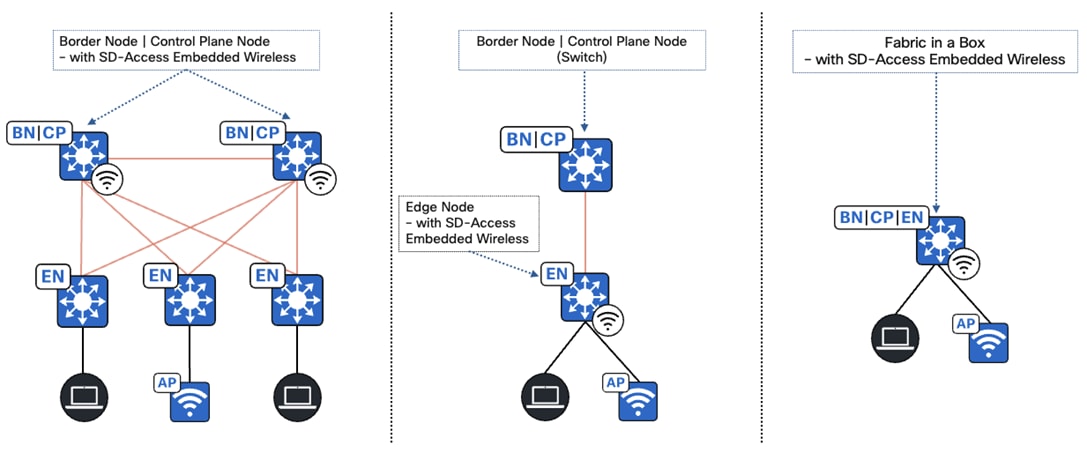
Fabric in a Box
Fabric In a Box (FIAB) integrates all the functionalities of a traditional SD-Access network such as border node, control plane node, and edge node into a single physical device. This device can be a single switch, a switch with hardware stacking capabilities, or part of a StackWise Virtual (SVL) deployment.
FIAB provides these benefits:
● Simplicity.
● Cost-effectiveness.
● Faster deployment.
● Ideal for branches and small-sized deployments.
For more information, refer to the Cisco Catalyst 9000 Platform StackWise Virtual White Paper.
SD-Access embedded wireless
For distributed branches and small campuses, wireless controller functionality can be achieved without a hardware wireless controller through the Cisco Catalyst 9800 Embedded Wireless Controller, available as a software package for Catalyst 9000 series switches.
The Catalyst 9800 Embedded Wireless Controller is supported for SD-Access deployments in three topologies:
● Cisco Catalyst 9000 Series switches function as colocated border and control plane.
● Cisco Catalyst 9000 Series switches function as an edge node when the border and control plane node are on a routing platform.
● Cisco Catalyst 9000 Series switches function as fabric consolidation.
Tech tip: All Catalyst 9000 switches support the SD-Access embedded wireless functionality with the exception of the Catalyst 9200, 9200L, 9500X and 9600 Series Switches. The embedded controller supports only fabric-mode APs used in SD-Access deployments.
Transits
Transits can connect multiple fabric sites or link a fabric site to non-fabric domains such as a data center or the Internet. Transits are a Cisco SD-Access construct that defines how Catalyst Center will automate the border node configuration for connections between fabric sites or between a fabric site and an external domain.
These are two types of transits:
● IP-based transit:
With IP-based transits, the fabric VXLAN header is removed, leaving the original native IP packet. When in native IP form, packets are forwarded using traditional routing and switching protocols between fabric sites. Unlike an SD-Access transit, an IP-based transit is provisioned with a VRF-Lite connection to an upstream peer-device. IP-based transits typically connect to a data center, WAN, or the Internet. Use an IP-based transit to connect to shared services using a VRF-aware peer.
● SD-Access transit:
An SD-Access Transit uses VXLAN encapsulation and does not rely on a VRF-Lite connection to an upstream peer. Like IP-based transits, packets are forwarded using traditional routing and switching protocols between Fabric Sites. However, unlike IP-Based Transits, an SD-Access transit is an overlay that operates on top of a WAN/MAN network, much like SD-WAN and Dynamic Multipoint VPN (DMVPN).
Here is a comparison between IP-based transit and SD-Access transit:
IP-based transit:
● Leverages existing IP infrastructure:
Uses traditional IP-based routing protocols to connect fabric sites.
● Requires VRF remapping:
VRFs and SGTs require to be remapped between sites, adding complexity.
● Suitable for existing IP networks:
This approach is ideal if you already have an established IP-based WAN infrastructure.
● Offers flexibility:
Provides more flexibility in terms of routing protocols and traffic engineering options.
SD-Access transit:
● Native SD-Access fabric:
Uses LISP, VXLAN, and CTS for intersite communication.
● Preserves SGTs:
Maintains SGTs across fabric sites, enhancing security and policy enforcement.
● Centralized control:
Uses a domain-wide control plane node for simplified management.
● Requires dedicated infrastructure:
Requires additional infrastructure for the SD-Access transit control plane.
Ensure these key considerations when using an SD-Access transit:
● Connections should accommodate the recommended MTU settings used for Cisco SD-Access in the campus network.
● IP reachability must exist between fabric sites. Specifically, a known underlay route must be present between all fabric nodes. The default route cannot be used for this purpose.
● Support for underlay SSM is necessary if multicast traffic will traverse SD-Access transit.
For more information, refer to the Cisco SD-Access.
Compatibility matrix
Catalyst Center provides coverage for Cisco enterprise switching, routing, and mobility products. See the compatibility matrix for a complete list of supported Cisco products:
● Cisco Catalyst Center Compatibility Matrix
● Cisco SD-Access Compatibility Matrix
ITES profile deployment
This section provides design guidance for the ITES sector, emphasizing its requirements and the use of Cisco SD-Access to create a network that is simple, secure, and flexible.
The topologies, use cases, and solutions discussed here focus on meeting the standard deployment options for ITES while addressing their themes and requirements.
ITES solution topology
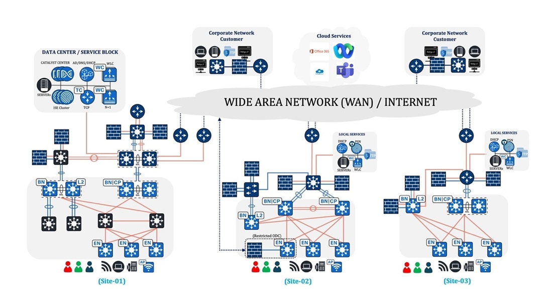
Overview of device and firewall placement in the topology:
Site-01: Large site
● Cat9600 SVL switch serves as both the border node and the control plane node.
● Cat9500 SVL switch serves as a dedicated Layer 2 border node.
● Cat9300 and 9400 switches serve as edge nodes.
● C2S/S2S firewalls functioning as gateways are connected to an aggregation switch positioned beyond the Layer 2 border.
● C2S/S2S firewalls that do not function as gateways are connected to an aggregation switch located beyond the fusion node.
Site-02: Medium site
● Cat9500 switch serves as both the border node and the control plane node.
● Cat9500 switch serves as a dedicated Layer 2 border node.
● Cat9200 and 9400 switches serve as edge nodes.
● C2S/S2S firewalls functioning as gateways are connected to an aggregation switch positioned beyond the Layer 2 border.
● C2S/S2S firewalls that do not function as gateways are connected directly to the fusion node.
Site-03: Small site
● Cat9500 SVL switch serves as both the border node and the control plane node.
● Cat9500 switch serves as a dedicated Layer 2 border node.
● Cat9300 switches serve as edge nodes.
● C2S/S2S firewalls functioning as gateways are connected directly to the Layer 2 border.
● C2S/S2S firewalls that do not function as gateways are connected directly to the fusion node.
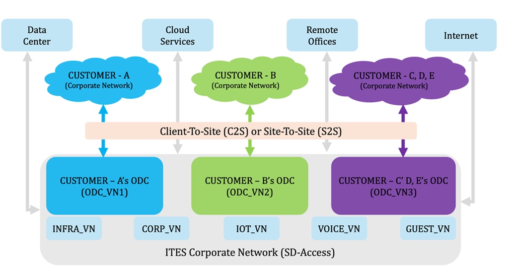
ITES logical diagram
Figure 4 outlines the network architecture of an ITES environment, depicting the connections between customer networks and ITES corporate networks. It highlights the secure and efficient data flow across various segments within an SD-Access infrastructure.
Business outcome and challenges
ITES (Information Technology Enabled Services) refers to the outsourcing of various processes and services, enabled by technology. Businesses across industries are increasingly leveraging ITES to improve efficiency, reduce costs, and enhance customer experience. However, like any business endeavors, ITES comes with its own set of challenges and potential outcomes, for example:
● Security
● Compliance
● Operational
● Financial
● Experience
Security
For an ITES company, enhancing security measures, mitigating risks, and ensuring compliance with regulatory standards can be achieved by implementing robust security protocols, conducting regular risk assessments, and adhering to industry-specific regulations and standards. Cybersecurity threats pose the greatest concern for an ITES company's Chief Information Security Officer (CISO). The rapid shift to hybrid work and the evolution of digital business services for customers have significantly increased the attack surface vectors available to cybercriminals. Unchecked, these malicious actors can exploit vulnerabilities, leading to substantial losses both financially and in terms of reputation. The CISO group regularly reviews fundamental security practices and processes.
Compliance
For an ITES company, compliance with regulatory standards is paramount to maintain trust, security, and legality in their operations. These companies are often entrusted with handling sensitive data and providing critical services to clients across various industries. Thus, adherence to compliance regulations is essential to ensure the confidentiality, integrity, and availability of data. Non-compliance not only exposes ITES companies to legal repercussions but also risks damaging their reputation and losing valuable client trust. Therefore, a proactive approach to compliance is crucial for the success and sustainability of ITES companies in today's regulatory landscape.
Operational
For ITES companies, network uptime is paramount to smooth operations and achieving business goals. Since ITES networks are mission-critical, the ultimate goal is to get as close to 100% availability as possible. Five-nines availability (99.999% uptime) represents a significant step towards this objective, allowing only 5 minutes and 16 seconds of downtime annually. Seamless and uninterrupted services are essential for ITES customer productivity and business success. By implementing automation, monitoring, load balancing, and failover mechanisms, ITES firms can achieve or even surpass the five-nines availability target.
Financial
Operational expenses are a major focus for ITES businesses. Streamline expenses and boost earnings through the automation of deployment across thousands of sites while minimizing the need for on-site network operations whenever feasible. Large-scale multisite deployments are common in the ITES sector, often encompassing hundreds of Offshore Development Centers (ODCs) distributed across extensive geographic areas. Managing such networks box-by-box or site-by-site with onsite teams poses significant challenges.
To address the complex requirements of ITES, a solution is required to quickly set up any site or ODC in any location and manage it remotely. This enables ITES organizations to maintain an efficient IT staff. Achieving this entails implementing network automation and monitoring to streamline deployment and troubleshooting procedures.
Experience
Enhance user and application experiences by strategically utilizing modern technologies that support essential business capabilities. Beyond security, compliance, and availability concerns, a network with inconsistent or slow QoS can lead to poor customer satisfaction and financial losses. In environments such as time-sensitive operations, where delays are critical, low latency and consistent QoS are crucial to meet organizational requirements.
Solutions to ITES business outcomes
This section outlines solutions to help achieve the business outcomes defined for the ITES network deployment.
Security challenges
The Information Technology Enabled Services (ITES) sector faces significant security challenges due to its complex and dynamic environment, including increased attack surfaces, data breaches, insider threats, regulatory compliance requirements, sophisticated cyber-attacks, and the security of remote work. Cisco’s SD-Access framework addresses these challenges through a comprehensive set of tools and capabilities, such as:
● Macrosegmentation
● Microsegmentation
● Policy enforcement models
● Group-based policy analytics
● Segment optimization and management
● AI endpoint analytics
● Endpoint security with zero-trust solution
● Isolation of guest users
● Enhancing security with external gateways.
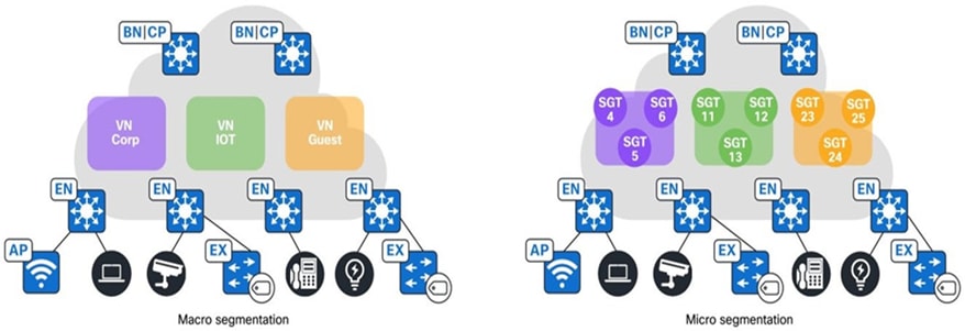
Macrosegmentation
For ITES networks, assign different virtual routing and VRFs network endpoints such as employees, monitoring devices, and guests to implement a recommended segmentation strategy. SD‑Access offers the ability to macrosegment endpoints into different VRFs, which can be configured within the network using Catalyst Center.
Here are a few examples demonstrating the implementation of VNs:
● INFRA VN:
This VN is exclusively for APs, classic and policy extended nodes for connectivity and is mapped to the global routing table.
● Employee VN:
Use this VN for regular employee access, ensuring secure and segregated connectivity for all internal users.
● Guest VN:
This VN provides internet access to visitors and guests while ensuring they cannot access the internal network.
● Monitoring VN:
Use this VN to dedicate network monitoring and management devices, ensuring they are isolated from regular user traffic.
● ODC VN:
Use this VN for employees working on client projects, ensuring secure and segregated connectivity to the client’s corporate network.
An ITES company can effectively segment and secure diverse types of traffic, enhance overall network performance and security by implementing VNs in an SD-Access network.
Microsegmentation
Microsegmentation simplifies the provisioning and management of network access control by using security groups to classify traffic and enforce policies, allowing for more granular security within SD‑Access VNs.
Typically, within a single VN, you should further segment by grouping employees based on their department or placing devices such as printers in different security groups. Traditionally, this was done by placing groups in different subnets enforced by IP ACLs. However, Cisco SD-Access provides the flexibility of microsegmentation, allowing the use of the same subnet with a user and endpoint-centric approach. Dynamic authorization assigns different SGTs based on authentication credentials and Security‑Group Access Control Lists (SGACLs) enforces these SGT-based rules.
When users connect to the network, they are authenticated using methods such as 802.1X and MAC authentication bypass (MAB). Network authorization then classifies the user’s traffic using information such as identity, LDAP group membership, location, and access type. This classification information is propagated to a network device that enforces the dynamically downloaded policy, determining whether the traffic should be allowed or denied.
For more information, refer to the Software-Defined Access Macrosegmentation Deployment Guide.
Figure 5 provides an example illustrating both macrosegmentation and microsegmentation:
Policy enforcement models
Cisco TrustSec is a security solution designed to simplify network access provisioning and management while enforcing security policies across an organization. It enables comprehensive segmentation and access control based on roles and policies rather than traditional IP-based methods, enhancing security and operational efficiency across wired and wireless environments.
In computing and network security enforcement, policy enforcement models generally fall into two categories:
● Deny-list model (default permit IP):
The default action permits IP traffic, and any restrictions must be explicitly configured using SGACLs. Use this model when there is an incomplete understanding of traffic flows within the network. It is relatively easy to implement.
● Allow-list model (default deny IP):
The default action denies IP traffic, so the required traffic must be explicitly permitted using SGACLs. Use this model when the customer has a good understanding of traffic flows within the network. This requires a detailed study of the control plane traffic, as it can block all traffic upon activation.
For more details on the policy enforcement model, refer to the Cisco ISE TrustSec Allow-List Model (Default Deny IP) with SDA.
Group-based policy analytics
High-profile cyber-attack news is driving ITES organizations to move beyond perimeter security and implement internal network segmentation. However, the lack of visibility into user and device behavior within the network makes it difficult to create effective segmentation policies. Businesses are seeking solutions to navigate this complex landscape.
Cisco offers a solution on Catalyst Center that addresses these challenges by providing Group-Based Policy Analytics (GBPA). GBPA empowers network administrators with these capabilities:
● Discover and visualize group interactions:
GBPA analyzes network traffic flows to identify how different network groups such as departments, functions, etc., communicate.
● Identify communication patterns:
GBPA pinpoints the specific ports and protocols used by different groups, providing granular insights into network behavior.
● Simplify policy creation:
GBPA streamlines the process of building effective security policies to control communication between groups based on the discovered information.
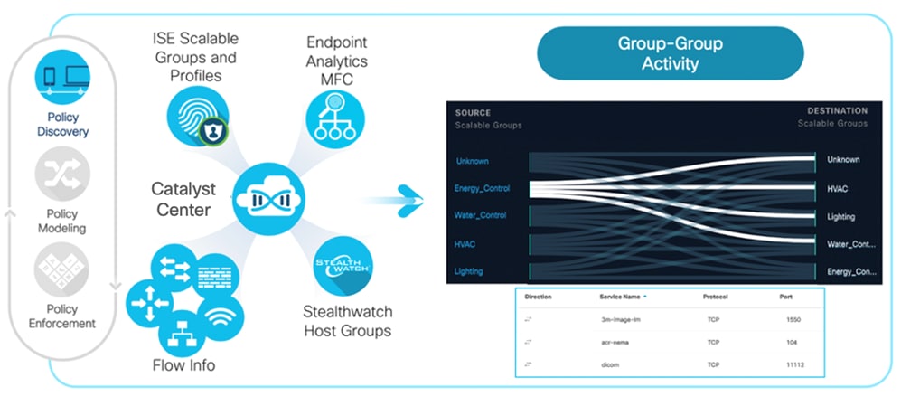
As seen in Figure 6, GBPA leverages information from these sources to create a holistic view of your network:
● Cisco ISE:
When integrated with ISE, GBPA learns about network groups defined as Scalable Groups and Profile Groups, which categorize different types of connected devices.
● Endpoint analytics:
Endpoint Analytics leverages machine learning and multifactor classification to reduce unidentified devices on the network and provides more accurate profile groups for segmentation.
● Cisco Secure Network Analytics (Optional):
Integration with Cisco Secure Network Analytics (SNA) allows GBPA to learn about Host Groups identified by SNA, further enriching network visibility.
● NetFlow data integration:
GBPA incorporates NetFlow data from network devices to provide context for group information. This combined data is then visualized through graphs and tables, enabling administrators to clearly understand network behavior based on group interactions.
GBPA empowers network administrators with network discovery, visualization, and the tools to analyze security policy requirements. This comprehensive approach leads to the creation of more effective and targeted security policies for today's dynamic threat landscape.
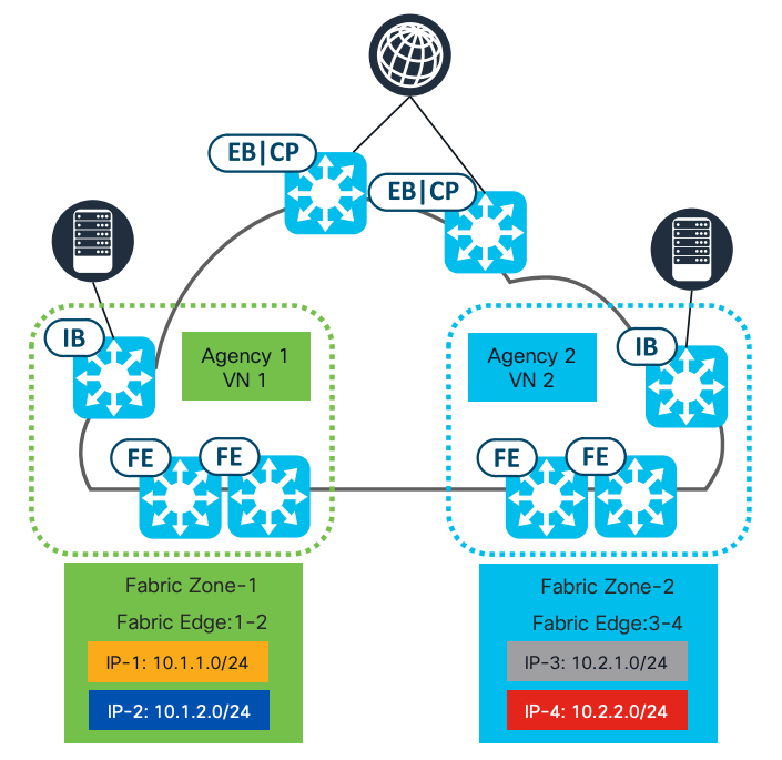
Segment optimization and management
Fabric zones are essential components in SD-Access architectures, providing a structured approach to managing, securing, and optimizing large-scale deployments.
● Manageability:
Fabric zones allow for the logical grouping of devices based on physical or logical boundaries (for example: buildings, floors, departments).
● Security:
Fabric zones enable granular control over VN and IP pool provisioning within a site.
● Scalability and performance:
By grouping devices into zones, fabric zones reduce provisioning time across fabric edge nodes.
Fabric zones provide a means to confine Layer 2 VNs and anycast gateways within specific sections of a fabric site, such as individual buildings. They are not mandatory and are confined within a fabric site, housing only edge nodes and extended nodes. In the event fabric zones are used, only designated VNs and anycast gateways (IP address pools) are allocated to the edge nodes within each fabric zone.
In the absence of fabric zones, all VNs and anycast gateways are allocated to every edge node within the fabric site. Upon relocating a design hierarchy element into a fabric zone, all existing edge nodes provisioned at or below this element will be automatically transferred into the respective fabric zone. This transition does not disrupt user traffic.
Figure 7 illustrates an example of a fabric zone configuration.
AI endpoint analytics
Cisco AI (Artificial Intelligence) Endpoint Analytics, next-generation endpoint visibility solution, provides deeper insights from your network and IT ecosystem, making all endpoints visible and searchable. It detects and reduces the number of unknown endpoints in your enterprise using these techniques:
● Deep Packet Inspection (DPI):
Gathers deeper endpoint context by scanning and understanding applications and communication protocols for IT, Building Automation, and Healthcare endpoints.
● Machine Learning (ML):
Intuitively groups endpoints with common attributes and helps IT administrators label them. These unique labels are then anonymously shared with other organizations as suggestions, assisting in reducing the number of unknown endpoints and grouping them based on new labels.
● Integrations with Cisco and third-party products:
Provides additional network and non-network context used to profile endpoints.
In summary, Cisco AI Endpoint Analytics addresses a critical challenge faced by many customers when implementing security policies: overcoming the lack of endpoint visibility, with high fidelity. It is available in Cisco Catalyst Center Release 2.1.2.x and higher as a new application. Customers with a subscription level of Cisco Catalyst Advantage and higher will have access to Cisco AI Endpoint Analytics. This technology primer will explore Cisco AI Endpoint Analytics and the benefits it offers to Cisco customers.
For more information, refer to:
● Cisco SD-Access AI Endpoint Analytics
● Cisco Catalyst Center Guide - AI Endpoint Analytics
Endpoint security with zero-trust solution
Endpoint security with zero-trust solutions in SD-Access is a comprehensive approach to network security that aims to protect endpoints, such as laptops, smartphones, and IoT devices, within a SD‑Access environment. Zero-trust principles are applied, which means that no device or user is automatically trusted, even if they are inside the network perimeter. Each device is verified and authenticated before being granted access to network resources.
Cisco SD-Access zero-trust security solution provides the capability to automate network access policies using these features:
● Endpoint visibility:
You can identify and group endpoints. You can map their interactions through traffic flow analysis and define access policies.
● Trust monitoring:
You can continuously monitor the endpoint behavior, scan for vulnerabilities, verify trustworthiness for continued access, and isolate rogue or compromised endpoints.
● Network segmentation:
You can enforce group-based access policies and secure network through multilevel segmentation.
Cisco SD-Access can enforce the secure onboarding of network devices such as APs and switches using IEEE 802.1x mechanisms. This protects the network from unauthorized device attachment by maintaining closed authentication on all edge node access ports. Switches onboarded securely using closed authentication are termed Supplicant-Based Extended Nodes (SBEN).
SBEN are provisioned as policy extended nodes by Cisco Catalyst Center to have a supplicant with EAP‑TLS authentication on their uplink to the edge node. The EAP-TLS certificate is provisioned by Cisco Catalyst Center using the Cisco Catalyst Center Certificate Authority (CA). After successful onboarding, access to the port is purely based on authentication status. If the device or port goes down, the authentication session is cleared, and traffic is not allowed on the port. When the port comes back, it goes through dot1x authentication to regain access to the Cisco SD-Access network.
Secure AP onboarding is achieved by authorizing the AP on a closed authentication port, allowing limited access to DHCP/DNS and Cisco Catalyst Center for the PnP workflow. The PnP workflow on the Cisco Catalyst Center was enhanced to enable a dot1x supplicant on the AP, which the AP uses to authenticate with Cisco ISE.
For more information, refer to the "Configure Supplicant-Based Extended Nodes" section in the Cisco Catalyst Center User Guide.
Isolation of guest users
In SD-Access, guest wireless deployment ensures robust isolation from the corporate network through the implementation of VNs and SGTs. A dedicated VN is created for guest access, and SGTs are employed to tag guest traffic and enforce granular access policies. These policies prevent guest users from accessing corporate resources and restrict their internet access to specified, permitted services. The isolation is enforced by the fabric edge nodes and border nodes, which filter and forward traffic according to the defined policies. This guarantees that guest users receive an isolated and secure connection without compromising the integrity of the corporate network.
For multi-site deployments, SD-Access leverages the multisite remote border (MSRB) to extend this secure guest wireless experience across geographically dispersed locations. The MSRB function allows guest traffic to be routed directly to the internet via the home site from the remote site, minimizing latency and optimizing bandwidth utilization. By maintaining the same VN and SGT policies across all sites, a consistent and secure guest experience is delivered, regardless of the user's location. This approach ensures that guest traffic remains isolated from the corporate network, even as it traverses multiple sites, and simplifies management by centralizing policy control within the SD-Access fabric.
Cisco Catalyst Center configures Central Web Authentication (CWA), External Web Authentication (EWA), and hotspot SSIDs on Cisco AireOS and Polaris-based Wireless LAN Controllers (Cisco Catalyst 9800 and embedded wireless on Cisco Catalyst 9000 platforms) to enable guest access flow in Cisco SD-Access network.
For more information, refer to this configuration guide:
● Cisco Catalyst Center SD-Access Guest Automation
Enhancing security with external gateways
In SD-Access, a default gateway is present on all edge nodes for each subnet in a VN within a given fabric site. Traffic destined for a remote subnet is processed by the default gateway on the edge node and then routed to the appropriate destination.
In many networks, the default gateway needs to be on an external firewall rather than on the local edge node. Firewall traffic inspection is a common security and compliance requirement in such networks. By enabling the gateway outside of the fabric functionality, the default gateway is not provisioned on the edge nodes. Instead, it can be provisioned on an external device, such as a firewall, allowing traffic to be inspected before reaching its destination.
Compliance regulations
Compliance regulations refer to the set of rules and standards that organizations must adhere to operate lawfully within a particular industry or jurisdiction. These technologies aid in ensuring compliance by automating regulatory processes, enhancing data security, and providing real-time monitoring and reporting capabilities to meet regulatory requirements effectively. Staying compliant with industry regulations can be a complex task. Cisco SD-Access offers several features that can simplify this process:
● Role-Based Access Control
● Audit logs
● Configuration compliance
● Configuration drift
Role-Based Access Control
Role-Based Access Control (RBAC) in Catalyst Center provides a way to control access to features and operations based on the roles of individual users within the organization. RBAC helps enforce the principle of least privilege, ensuring that users have access only to the resources necessary for their roles. Catalyst Center supports the flexibility to assign permissions to users based on either a local or external RADIUS/TACACS database. You can assign roles to users and also grant access to specific applications within Catalyst Center.
For more information, refer to the “Manage Users” section in the Cisco Catalyst Center Administrator Guide.
Audit logs
Audit logs refer to a record of events or actions that have occurred within the Catalyst Center application. These logs typically include details such as who did the action, what action was taken, and when it occurred. Audit logs are important for security and compliance purposes, as they help administrators track changes made to the network infrastructure, identify potential security breaches, and ensure that users are following proper procedures. By reviewing audit logs, administrators can gain insight into the activities within the Catalyst Center application and take appropriate actions as needed.
For more information, refer to the “View Audit Logs” section in the Cisco Catalyst Center Administrator Guide.
Configuration compliance
Compliance helps in identifying any intent deviation or out-of-band changes in the network that may be injected or reconfigured without affecting the original content. A network administrator can conveniently identify devices in Catalyst Center that do not meet compliance requirements for the various aspects of compliance, such as software images, PSIRT, network profiles, and so on.
You can automate compliance checks or do on demand using these schedule options:
● Automated compliance check:
Use the latest data collected from devices in Catalyst Center. This compliance check listens to the traps and notifications from various services, such as inventory and SWIM, to assess data.
● Manual compliance check:
Lets you manually trigger the compliance in Catalyst Center.
● Scheduled compliance check:
A scheduled compliance job runs every day at 11:00 pm and triggers the compliance check for devices that have not undergone a compliance check in the past seven days.
Catalyst Center currently supports these types of compliance checks:
● Flag compliance errors when running configuration on network devices differs from the startup configuration view that Catalyst Center has for the device.
● Software image compliance flag to indicate if the golden image is not running on network devices.
● Flag fabric compliance errors if the configurations deployed by the SD-Access fabric workflows were tampered with, breaching out-of-band PSIRT compliance, to alert network administrators to existing vulnerabilities in the network.
● Network compliance alerts if the devices are not running configuration per the intent called out for the given site in Catalyst Center.
For more information, refer to the “Compliance Audit for Network Devices” in the Cisco Catalyst Center User Guide.
Configuration drift
Configuration drift occurs when the actual configuration settings of network devices deviate from their intended or predefined state over time. In ITES organizations, compliance mandates often require maintaining archives of configurations for all network devices. Catalyst Center offers support for configuration drift, allowing users to track and monitor changes in device configurations. This feature enables users to review the current configuration of each device and analyze historical changes from the past month to understand how configurations have evolved over time on a specific device.
For more information, refer to the “Configuration Drift of a Devices” in the Cisco Catalyst Center User Guide.
Operational efficiency
Operational efficiency is vital for ITES businesses, directly enhancing productivity, cost-effectiveness, and service quality. This efficiency enables them to maximize employee output, streamline digital transformation efforts, and enhance their reputation and brand value. SD-Access addresses these key aspects of operational efficiency:
● High availability
● System resiliency
● Reports
● Efficient troubleshooting
High availability
High availability (HA) is a critical component that ensures systems and applications remain operational and accessible to users with minimal interruption, even during technical setbacks such as hardware failures or software glitches. Here's an overview of achieving HA for these components:
● Disaster recovery
● Resilient network architecture
● Fallback segments
Disaster recovery
ITES organizations have a low tolerance for management, control, or data plane failure. Catalyst Center supports both intracluster and intercluster resiliency. The Disaster Recovery implementation in Catalyst Center consists of three components: the main site, the recovery site, and the witness site. At any given time, the main and recovery sites operate in either active or standby roles. The active site manages your network, while the standby site maintains a continuously updated copy of the active site's data and managed services. Whenever an active site goes down, Catalyst Center automatically initiates a failover, completing the tasks necessary to designate the former standby site as the new active site.
For more information, refer to the “Implement Disaster Recovery” section in the Cisco Catalyst Center Administrator Guide.
Resilient network architecture
Resilient network architecture in SD-Access is designed to provide a highly available and reliable network infrastructure, ensuring that critical services remain operational even in the face of disruptions.
● Similar to Virtual Switching System (VSS), SVL simplifies Layer 2 operations by combining two physical switches into a single logical switch at the control and management plane level. This can remove the requirement for spanning tree and first hop redundancy protocols, and their related configurations.
● With Layer 3 routed access, the boundary between Layer 2 and Layer 3 shifts from the distribution layer to the access layer. This eliminates the need for the distribution and collapsed core layers to handle Layer 2 adjacency and redundancy.
In ITES networks, alongside traditional resilience methods like stacking and SVL, regional hubs and campus headquarters often need protection from building failures to ensure continuous connectivity to data centers for critical applications.
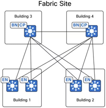
Cisco SD-Access provides a flexible deployment architecture that allows fabric borders to be positioned in different physical sites while integrating them under a single fabric site. As depicted in the figure, Buildings 1 through 4 belong to the same fabric site, with the colocated border nodes and control plane nodes located in different buildings. Cisco SD-Access offers the flexibility to designate priorities to these border node deployments. This allows for the prioritization of a border node or its exclusive use as the active border for traffic. In the event of a building failure, the border node in the alternate building can seamlessly assume all traffic from the edge nodes.
Fallback segments
In Cisco SD-Access, there is support for a Critical VLAN feature, which ensures that endpoints maintain a minimum level of network connectivity even when they lose connectivity to their ISE server due to outages like a WAN outage. For clients that have already been onboarded, if the connection to the ISE Policy Service Node is lost, the system pauses periodic re-authorization to prevent disruptions in the authentication path from affecting the data plane. For clients that have not yet been onboarded, the Critical VLAN feature assigns them to a specific VLAN if connectivity to ISE is lost, providing them with limited network access.
These Critical VLANs can use micro-segmentation to enforce policies in the absence of ISE, but to achieve this, assign a security group during the provisioning of the anycast gateway for the critical VLAN such as VLAN-SGT mapping and configure the appropriate policy matrix to be downloaded onto the switches. In summary, Critical VLAN in SD-Access ensures that even when devices cannot authenticate properly, they are not entirely disconnected from the network but are given limited access for remediation and troubleshooting purposes.
System resiliency
To ensure system resiliency, it is important to implement HA and redundancy solutions for critical components of the network infrastructure. Here is an overview of how to achieve this for these components:
● Catalyst Center HA
● ISE HA
● Cisco Wireless LAN Controller redundancy
Catalyst Center HA
Catalyst Center's HA is a feature designed to minimize downtime and increase network resilience. It achieves this by ensuring that critical services remain available in the event of hardware or software failures. HA in Catalyst Center typically involves deploying redundant hardware and software configurations to provide seamless failover and continuous operation. This helps organizations maintain network stability and reliability, even during unexpected events.
For more information, refer to Cisco Catalyst Center High Availability Guide.
ISE HA
Cisco ISE can be deployed in two main configurations:
● Standalone deployment:
In a standalone deployment, a single ISE node serves all the necessary functions, including administration, policy services, and monitoring. This configuration is suitable for smaller networks where a single node can handle the workload and redundancy is not a critical requirement
● Distributed deployment:
In a distributed deployment, ISE nodes are distributed across multiple physical or virtual machines to provide scalability, redundancy, and HA. This configuration is suitable for larger networks where scalability and redundancy are important.
Each deployment option has its own advantages and is chosen based on the specific requirements of the network in terms of scalability, redundancy, and performance. To support failover and to improve performance, you can set up a deployment with multiple Cisco ISE nodes in a distributed fashion.
For more information, refer to the "Distributed Deployment Scenarios" in the Cisco Identity Services Engine Installation Guide.
Cisco Wireless LAN Controller redundancy
Cisco Wireless LAN Controller redundancy is essential for maintaining continuous wireless network services. In an HA pair setup, two wireless controllers are configured as a pair. One wireless controller functions as the primary (active) controller, managing all wireless clients and traffic, while the other serves as the secondary (standby) controller. The secondary controller stays synchronized with the primary controller's configuration and state.
If the primary controller encounters an issue, the secondary controller seamlessly takes over, ensuring uninterrupted wireless service. This redundancy feature significantly improves the reliability of wireless networks, providing failover capabilities in the event of wireless controller hardware or software failures. Consequently, users experience minimal disruption and maintain connectivity to the wireless network.
For more information, refer to the Cisco Catalyst 9800 Series Wireless Controllers High Availability SSO Deployment Guide.
Reports
The Catalyst Center Reports feature provides a comprehensive suite of tools for deriving actionable insights into your network's operational efficiency. This feature enables data generation in multiple formats, with flexible scheduling and configuration options, allowing for tailored customization to meet your specific operational needs.
The Reports feature supports various use cases that include:
● Capacity planning:
Understanding device utilization within your network.
● Pattern change analysis:
Tracking changes in usage patterns, including clients, devices, bands, and applications.
● Operational reporting:
Reviewing reports on network operations, such as upgrade completions and provisioning failures.
● Network health assessment:
Evaluating the overall health of your network through detailed reports.
By leveraging Catalyst Center's reporting capabilities, you can significantly enhance your network's operational efficiency, ensuring a smooth-running, high-performing network environment.
For more information, refer to the “Reports” section in the Cisco Catalyst Center Platform User Guide.
Efficient troubleshooting
Efficient troubleshooting is a critical component to support business operations for ITES customers. Catalyst Center offers comprehensive debugging ability features designed to meet these needs effectively. These features empower IT administrators to quickly identify, diagnose, and resolve Catalyst Center issues, ensuring continuous and optimal performance of the network infrastructure. These tools help with troubleshooting:
● Validation Tool:
Before Catalyst Center 2.3.5.x, the Audit and Upgrade Readiness Analyzer (AURA) tool assessed the upgrade readiness of a cluster. With the restricted shell fully implemented in 2.3.5.x, most of the AURA upgrade checks are now implemented in Catalyst Center. The Validation Tool tests both Catalyst Center appliance hardware and connected external systems and identifies any issues that need to be addressed before they seriously impact your network.
◦ Validate Cisco DNA Center Upgrade Readiness
◦ Use the System Analyzer Tool
● System Analyzer:
To address troubleshooting needs, the System Analyzer tool provides efficient log file retrieval. The System Analyzer does comprehensive assessments and diagnostics to ensure the optimal functioning and reliability of Catalyst Center and its connected network components. By leveraging the System Analyzer capabilities for monitoring, diagnostics, and performance optimization, organizations can enhance operational efficiency, ensure compliance with security standards, and deliver reliable ITES services.
Overall, the Catalyst Center Validation Tool and System Analyzer are invaluable assets for ITES network administrators. These tools promote proactive maintenance, efficient troubleshooting, and enhanced network stability, significantly boosting operational efficiency for ITES delivery.
Financial efficiency
Reducing operational expenses and increasing earnings are major priorities for ITES businesses. By automating the deployment and monitoring of large-scale, multisite networks, ITES organizations can significantly reduce operational expenses, streamline processes, and maintain efficient IT operations. This approach enables the management of complex networks with minimal manual intervention, enhancing overall productivity and profitability.
Here are some of the approaches adopted for achieving financial efficiency in ITES organizations:
● Automation and monitoring
● IP address management integration
● IT service management integration
● SD-Access extension
Automation and monitoring
Automation and monitoring are essential components of modern IT infrastructure management. Automation can include tasks such as software deployment, configuration management, system provisioning, and workflow orchestration. By automating repetitive and time-consuming tasks, organizations can improve efficiency, reduce errors, and free up human resources to focus on more strategic activities. Monitoring, on the other hand, involves continuously observing and analyzing the performance and health of IT systems, networks, applications, and services.
Here is an overview of how to implement these strategies for these components:
● LAN automation
● Plug and Play and Return Material Authorization
● Software image management
● Intelligent capture
● Assurance and visibility
LAN automation
LAN automation in Catalyst Center is a feature designed to simplify the deployment and management of network infrastructure by automating the configuration and provisioning of network devices. This automation reduces the complexity and potential for errors associated with manual configuration, resulting in more efficient and reliable network operations.
Cisco LAN automation provides these key benefits:
● Zero-touch provisioning:
Network devices are dynamically discovered, onboarded, and automated from their factory-default state to fully integrated in the network.
● End-to-end topology:
Dynamic discovery of new network systems and their physical connectivity can be modeled and programmed. These new systems can be automated with Layer 3 IP addressing and routing protocols to dynamically build end-to-end routing topologies.
● Resilience:
LAN automation integrates system and network configuration parameters that optimize forwarding topologies and redundancy. LAN automation enables system-level redundancy and automates best practices to enable best-in-class resiliency during planned or unplanned network outages.
● Security:
Cisco-recommended network access and infrastructure protection parameters are automated, providing security from the initial deployment.
● Compliance:
LAN automation helps eliminate human errors, misconfiguration, and inconsistent rules and settings that drain IT resources. During new system onboarding, LAN automation provides compliance across the network infrastructure by automating globally managed parameters from Catalyst Center.
For more information, refer to the Cisco Catalyst Center SD-Access LAN Automation Deployment Guide.
Plug and Play and Return Material Authorization
Catalyst Center features Plug and Play (PnP) functionality, which simplifies the deployment of Cisco Catalyst switches, routers, and wireless APs. With PnP, network administrators can easily onboard new devices to the network without the need for manual configuration. Devices with PnP capability can automatically download the required software image and configuration from a PnP server, such as Catalyst Center, making the deployment process faster and more efficient.
Catalyst Center provides support for Return Material Authorization (RMA) processes. In case of hardware failure or replacement, the RMA feature allows administrators to easily manage the return and replacement of faulty devices. This includes generating RMA requests, tracking the status of RMAs, and managing the replacement process through a centralized interface. Overall, the PnP and RMA features in Catalyst Center help streamline device deployment and replacement processes, reducing complexity and enhancing network management efficiency.
For more information, refer to the Network Device Onboarding for Cisco Catalyst Center Deployment Guide.
Software image management
Catalyst Center's Software Image Management (SWIM) feature simplifies and automates the process of managing software images across Catalyst switches, routers, and wireless devices in the network. Network administrators who wish to automate the upgrade of a Catalyst 9000 series switch at a branch or campus can use the Catalyst Center SWIM solution.
Catalyst Center stores all unique software images according to image type and version for the devices in your network. It allows you to view, import, and delete software images and push them to your network's devices. The software upgrade can be optimized by decoupling software distribution and activation to minimize downtime within the maintenance window. Overall, SWIM enhances operational efficiency, reduces downtime, and helps ensure network security and compliance by simplifying and automating the management of software images across Catalyst devices.
For more information, refer to the SWIM Deployment Guide.
Intelligent Capture
Catalyst Center Intelligent Capture (iCap) is a powerful feature designed to enhance network troubleshooting and performance monitoring. It leverages advanced analytics and machine learning to provide deep insights into network traffic and client behaviors. iCap provides support for a direct communication link between Catalyst Center and APs, so each of the APs can communicate with Catalyst Center directly. Using this channel, Catalyst Center can receive packet capture (PCAP) data, AP and client statistics, and spectrum data. With the direct link from the AP to Catalyst Center through gRPC, iCap allows you to access data from APs that is not available from wireless controllers.
For more information, refer to the Cisco Intelligent Capture Deployment Guide.
Assurance and visibility
Catalyst Center manages your network by automating network devices and services but also provides network assurance and analytic capabilities. Catalyst Center collects telemetry from network devices, Cisco ISE, users, endpoints, applications, and other integrations across the network. Catalyst Center Network Analytics correlates data from various sources to help administrators or operators to offer comprehensive network insights into:
● Device 360 and Client 360:
View device or client connectivity, which includes information on topology, throughput, and latency from various times and different applications.
● Network time travel:
Ability to go back in time and refer to the cause of a network issue.
● Application experience:
Provide unparalleled visibility and performance control on the applications critical to your core business on a per-user basis.
● Network analytics:
Provide recommended corrective actions for found issues in the network. These actions can involve guided remediation, where the engine specifies steps for a network administrator to do.
For more information, refer to the Cisco Catalyst Assurance.
IP address management integration
IP address management (IPAM) integration in Catalyst Center streamlines the process of managing IP addresses within a network. This integration provides a centralized platform to automate and simplify IP address allocation, tracking, and management. In SD-Access deployments, IPAM integration provides Catalyst Center access to existing IP address scopes. When configuring new IP address pools in Catalyst Center, it automatically updates the IPAM server, reducing the IP address management tasks.
Two third-party integration modules are included in Catalyst Center, one for IPAM provider Infoblox and one for Bluecat. Other IPAM providers may be configured for use with Catalyst Center by providing an IPAM provider REST API service that meets the Catalyst Center IPAM provider specification.
For more information, refer to Configure an IP Address Manager.
IT Service Management integration
IT Service Management (ITSM) refers to the implementation and management of quality IT services that meet the needs of a business. ServiceNow is a popular ITSM platform that provides a suite of applications to help organizations automate and streamline their IT services.
Catalyst Center and ServiceNow integration supports these capabilities:
● Integrating Catalyst Center into ITSM processes of incident, event, change, and problem management.
● Integrating Catalyst Center into ITSM approval and preapproval chains.
● Integrating Catalyst Center with formal change and maintenance window schedules.
The scope of the integration is mainly to check your network for assurance and maintenance issues and for events requiring software image updates for compliance, security, or any other operational triggers. Details about these issues are then published to an ITSM (ServiceNow) system or any REST endpoint.
For more information, refer to the Cisco Catalyst Center ITSM Integration Guide.
SD-Access extension
SD-Access extension is a critical capability that allows organizations to extend the reach of their SD‑Access fabric, ensuring consistent policy enforcement, enhanced security, simplified management, and improved network performance across a broader range of environments and devices.
An extended node connects to the SD-Access in Layer 2 mode, facilitating the connection of IoT endpoints but does not support fabric technology. Using Catalyst Center, the extended node can be onboarded from a factory reset state through the PnP method, enabling security controls on the extended network and enforcing fabric policies for endpoints connected to the extended node.
To implement SD-Access extension, enterprise administrators can deploy extended nodes, which are available in three different types:
● Extended node (EX):
The extended node is a Layer 2 switch that connects to a fabric edge node in a Cisco SD-Access network. It provides connectivity for IoT endpoints and other devices that do not support full SD-Access capabilities. Extended nodes are typically managed and configured through a centralized controller like Catalyst Center. They rely on the fabric edge for advanced network functions like LISP, VXLAN, and SGACL enforcement.
● Policy extended node (PEN):
The policy extended node is a specific type of extended node that offers additional capabilities. It can do 802.1X/MAB authentication, dynamically assign VLANs and SGTs to endpoints, and enforce SGACLs. This type of node provides a more granular level of policy control compared to a standard extended node, allowing for more flexible network segmentation and security.
● SBEN:
The SBEN is an extended node that undergoes a stricter onboarding process. It requires an IEEE 802.1X supplicant configuration and completes a full authentication and authorization process before being allowed into the SD-Access network. This approach enhances security by ensuring that only authorized devices can access the network. SBENs are often used in environments with heightened security requirements.
Key points to remember:
● Extended nodes provide connectivity for endpoints that cannot directly participate in SD-Access.
● PEN offer enhanced policy enforcement capabilities.
● SBEN implement stricter security measures through 802.1X authentication.
Figure 9 illustrates the enterprise network using extended node (EX), policy extended node (PEN), and SBEN.
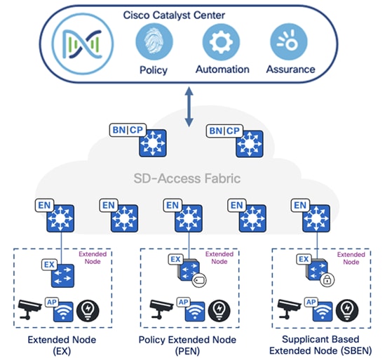
● For more information, refer to the "Extended node design" section of the Cisco SD-Access Solution Design Guide.
● For more information about extended nodes and PEN, refer to the Connected Communities Infrastructure - General Solution Design Guide.
Experience improvement
Enhancing user and customer experiences through strategic use of modern technologies involves prioritizing QoS, leveraging application visibility, and implementing video streaming, particularly in environments where performance directly impacts business operations and customer satisfaction. In today's competitive landscape, prioritizing QoS is not merely an option but a necessity for delivering exceptional user and customer experiences.
Here is an overview of strategies for enhancing these areas:
● QoS
● Application visibility
● Video streaming across sites
QoS
QoS refers to a network's capability to prioritize or differentiate service for selected types of network traffic. Configuring QoS ensures that network resources are utilized efficiently while meeting business objectives, such as ensuring enterprise-grade voice quality or delivering a high Quality of Experience (QoE) for video. Catalyst Center facilitates QoS configuration in your network through application policies.
These policies include these core parameters:
● Application sets:
Groups of applications with similar network traffic requirements. Each application set is categorized into business relevance groups (business relevant, default, or business irrelevant) that determine the priority of their traffic. QoS parameters for each group are defined according to Cisco Validated Design (CVD), and adjustments can be made to align with specific business goals.
● Site scope:
Defines the scope to which an application policy applies. For example, a wired policy applies to all wired devices within the specified site scope, while a wireless policy applies to devices using a specific Service Set Identifier (SSID) within the defined scope.
Application visibility
Application visibility is a feature that allows network administrators to see which applications are running on their network, monitor their performance, and understand how network resources are being utilized. This is crucial for maintaining optimal network performance, ensuring security, and improving the user experience.
Catalyst Center empowers you to manage and gain insights into applications traversing your network. This includes identifying built-in applications, custom applications, and categorizing network traffic. The application visibility service, hosted as an application stack within Catalyst Center, enables the Controller-Based Application Recognition (CBAR) function on a specific device to classify thousands of networks, home-grown applications, and network traffic.
Application visibility is achieved through a combination of deep packet inspection, flow analysis, and application recognition technologies, providing a comprehensive view of network activity and application performance. By implementing CBAR, organizations can ensure that their critical applications perform optimally, enhancing overall productivity and user satisfaction.
You can install these packages:
● Application policy:
Allows you to automate QoS policies across LAN, WAN, and wireless within your campus and branch.
● Application registry:
Allows you to view, manage, and create applications and application sets.
● Application visibility service:
Provides application classification using Network-Based Application Recognition (NBAR) and CBAR techniques.
Video streaming across sites
An ITES organization needs to conduct regular employee training sessions across multiple branch offices located in different regions. These training sessions include live video broadcasts of presentations, demonstrations, and interactive Q&A sessions. To efficiently distribute the video content to all branches simultaneously without overloading the network, the organization utilizes multicast technology.
Such multicast data can be streamed from various sources, including regional data centers and corporate data centers. The Cisco SD-Access architecture provides the flexibility for end-to-end seamless multicast data traffic to flow from anywhere within the larger enterprise network to any location globally. Cisco SD‑Access supports both headend replication and native multicast modes, offering the flexibility to assign Multicast RP (Rendezvous Points) nodes either within the SD-Access fabric or externally.
SD-Access supports two different transport methods for forwarding multicast traffic: one uses the overlay, referred to as Headend Replication, and the other uses the Underlay, known as Native Multicast.
● Headend replication:
Headend replication (or ingress replication) is done either by the multicast first-hop router (FHR) when the multicast source is in the fabric overlay, or by the border nodes when the source is outside the fabric site.
● Native Multicast:
Native Multicast does not require the ingress fabric node to do unicast replication. Instead, the entire underlay, including intermediate nodes, is used to handle the replication. To support Native Multicast, the first-hop routers (FHRs), last-hop routers (LHRs), and all network infrastructure components between them must be enabled.
By leveraging multicast technology within the SD-Access framework, the ITES organization can effectively conduct large-scale employee training sessions, enhancing communication and learning across all branch offices.
Network deployment options
These sections describe deployment options for an ITES network.
Fabric site reference models
In deployments with physical locations, you can use different templates for each of the different site types such as a large branch, a regional hub, headquarters, or small remote office. The underlying design challenge is to look at the existing network deployment and wiring and propose a method to layer SD‑Access fabric sites in these areas. This process can be simplified and streamlined by creating templates of the reference models. The templates help in understanding the common site designs by offering reference categories based on the multidimensional design elements along with the endpoint count to provide design guidelines for sites of similar size.
Each fabric site includes a supporting set of control plane nodes, edge nodes, border nodes, and wireless LAN controllers, sized appropriately from the listed categories. ISE PSN are also distributed across the sites to meet survivability requirements.
Common types of fabric site reference models include:
● FIAB site
● Small site
● Medium site
● Large site
Tech tip: These reference models offer valuable guidance. Adjustments may be necessary based on your specific network requirements and constraints. To ensure optimal deployment of your SD-Access fabric, we recommend that you consult with a network design professional.
For more information, refer to the Cisco SD-Access Solution Design Guide.
FIAB site reference model
The FIAB site reference model is designed for smaller university campuses or remote sites, typically supporting fewer than 1000 endpoints. The central component of this design is a switch stack or SVL, operating in all three fabric roles: control plane node, border node, and edge node. In switch stack FIAB deployment, SD-Access embedded wireless is commonly used to provide site-local wireless controller functionality. The site may also include an ISE PSN, depending on the WAN or internet circuit and latency.
Refer to Table 1 for guidelines on similar site design sizes. These numbers serve as general recommendations and may not represent exact limits for specific devices used in this site size.
Table 1. FIAB site guideline (limits may be different)
| Network element |
Scale |
| Endpoints, target fewer than |
1000 |
| Control plane nodes |
1 |
| External border nodes |
1 |
| APs, target fewer than |
50 |
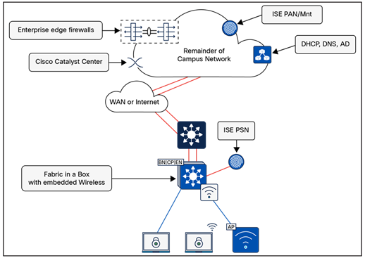
FIAB site consideration:
● Due to the smaller number of endpoints and the resulting lower impact, HA and site survivability are not common requirements for a Fabric in a Box design. With all reference designs, site‑local services such as DHCP, DNS, wireless controllers, and ISE can enhance resiliency and survivability, though this increases complexity and requires additional equipment, such as a services block.
● HA in this design is achieved through StackWise-480 or SVL, both of which combine multiple physical switches into a single logical switch. If a chassis-based switch is used, redundancy is ensured through dual supervisors and power supplies.
● Wireless controllers can be deployed as physical units directly connected to the FIAB or as an embedded Catalyst 9800 controller. When using the embedded Catalyst 9800 with a switch stack or redundant supervisor, AP and client Stateful Switchover (SSO) are provided automatically.
Small site reference model
The small site reference model applies to a single building with multiple wiring closets or multiple buildings and typically supports fewer than 10,000 endpoints. The physical network is usually a two-tier design, with a collapsed core/distribution layer and an access layer.
Refer to Table 2 for general design guidelines for similar site sizes. These numbers serve as reference points and may not represent exact limits for specific devices used in such designs.
Table 2. Small site guidelines (limits may be different)
| Network element |
Scale |
| Endpoints, target fewer than |
10,000 |
| Fabric nodes, target fewer than |
100 |
| Control plane nodes |
2 |
| External border nodes |
2 |
| APs, target fewer than |
500 |
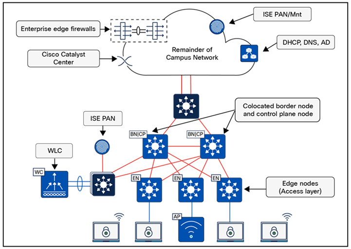
Small site considerations:
● For smaller deployments, an SD-Access fabric site is typically implemented using a two-tier design. In a small site, high availability is achieved by colocating the border and control plane node functionalities on the collapsed core switches and deploying them as a pair. To ensure resiliency and provide alternative forwarding paths in both the overlay and underlay, the collapsed core switches should be directly connected via a crosslink.
● The client and AP count necessitate the use of dedicated wireless controller. To establish highly available links for the wireless controller through physical connectivity, a services block is deployed. The wireless controllers connect to the services block switch via Layer 2 port channels, ensuring redundant interfaces. The services block, which consists of either a switch stack or SVL, connects to both collapsed core switches through Layer 3 routed links. If DHCP, DNS, and other shared services are site-local, the services block may be deployed as a VRF-aware peer.
Medium site reference model
The medium site reference model applies to a building with multiple wiring closets or multiple buildings and is designed to support fewer than 50,000 endpoints. The physical network typically follows a three-tier architecture, consisting of core, distribution, and access layers. The border and control plane node functions can be colocated or deployed on separate devices.
Refer to Table 3 for general design guidelines for sites of this scale. These numbers serve as recommendations and may not represent exact limits for specific network devices. To support the maximum endpoint capacity, a large Cisco Catalyst Center appliance is required, and in some cases, an extra-large appliance may be necessary.
Table 3. Medium site guidelines (limits may be different)
| Network element |
Scale |
| Endpoints, target fewer than |
50,000 |
| Fabric nodes, target fewer than |
500 |
| Control plane nodes (limit of 2 for FEW/SD-Access Wireless) |
2 to 6 |
| External border nodes |
2 |
| APs, target fewer than |
2500 |
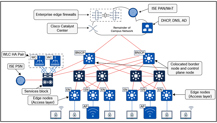
Medium site considerations:
● In a medium site, for both resiliency and alternative forwarding paths in the overlay and underlay, all devices within a given layer (except for the access layer) should be crosslinked to each other. Multiple distribution blocks do not need to be cross-connected to each other, but they should be cross‑connected to all distribution switches within a block. If dedicated control plane nodes are used, they are typically connected to the core switches to ensure high availability for any edge node across various distribution blocks. For optimal forwarding and redundancy, they should be connected to both core switches. If interfaces and fiber are available, they may also be crosslinked to each other, though this is not a strict requirement.
● Physical wireless controllers should be deployed to support the wireless user scale. To enable HA, a wireless controller HA-SSO pair is deployed with redundant physical connectivity to a services block using Layer 2 port channels. The services block is typically implemented with fixed-configuration switches operating as SVL and connected to the core through Layer 3 routed links. This services block may function as a VRF-aware peer if DHCP, DNS, and other shared services are site-local.
Large site reference model
The large site reference model applies to a building with multiple wiring closets or multiple buildings. The physical network typically follows a three-tier architecture (core, distribution, and access) and is designed to support up to 100,000 endpoints.
Refer to Table 4 for general design guidelines for sites of this scale. These numbers serve as reference points and may not correspond to specific device limitations within a given design. Supporting the maximum endpoint capacity requires, at minimum, an extra-large Cisco Catalyst Center appliance and may necessitate a three-node cluster of extra-large Catalyst Center appliances. The Cisco Catalyst Center data sheet provides details on the scalability of various networking infrastructure devices used to implement an SD-Access fabric site.
Table 4. Large site guidelines (limits may be different)
| Network element |
Scale |
| Endpoints, target fewer than |
50,000 |
| Fabric nodes, target fewer than |
500 |
| Control plane nodes (limit of 2 for FEW/SD-Access Wireless) |
2 to 6 |
| Border nodes (2 as internal and 2 as external) * In highly exceptional design scenarios, there may be multiple pairs of internal border nodes. |
2 to 4* |
| External border nodes |
2 |
| APs, target fewer than |
2500 |
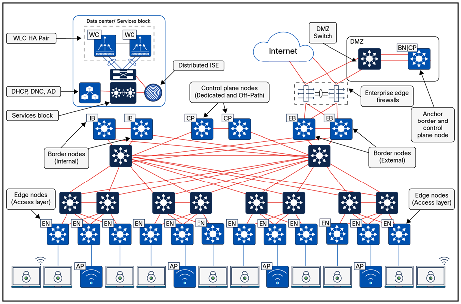
Large site considerations:
● Cisco Catalyst Center and the primary ISE PSN are typically deployed at a large site location.
● Control plane nodes and border nodes should be dedicated devices deployed in redundant pairs. Dedicated control plane nodes should connect to each core switch to ensure resiliency and provide redundant forwarding paths. If interfaces and fiber are available, crosslinking the control plane nodes is recommended, though not required, as it offers an additional underlay forwarding path.
● One or more wireless controller HA-SSO pairs are deployed with redundant physical connectivity to a services block using Layer 2 port channels. The services block is typically part of the on-premises data center network.
● Dedicated internal border nodes are sometimes used to connect the fabric site to the data center core, while dedicated external border nodes are used to connect the site to the MAN, WAN, and internet. We recommend that you deploy the least number of border nodes that meet network design requirements, because as the quantity of border nodes increases so does the SD-Access administrative effort and routing complexity. Dedicated redundant routing infrastructure and firewalls are used to connect this site to external resources, and border nodes fully mesh to this infrastructure and to each other.
● The large site may contain the demilitarized zone (DMZ) where the anchored fabric border and control plane nodes for guest wireless are deployed.
SD-Access for the distributed campus reference model
SD-Access for distributed campus is a solution that connects multiple independent fabric sites while maintaining security policy constructs (VRFs and SGTs) across these sites. Control plane signaling via the LISP protocol, along with fabric VXLAN encapsulation, is used between fabric sites. This ensures that macrosegmentation and microsegmentation policy constructs (VRFs and SGTs, respectively) are preserved. As a result, the network remains address-agnostic, enforcing end-to-end policies based on group membership.
In Figure 14, each fabric site is connected via a Metro Ethernet (Metro-E) private circuit. This deployment represents a large enterprise campus with multiple dispersed buildings within the same geographic area, where each building operates as an independent fabric site. The border nodes connected to this circuit are configured as external borders, colocated with a control plane node. IGP peering occurs across the circuit to establish IP reachability between the loopback interfaces (RLOCs) of the devices. The Metro-E circuit functions as the SD-Access transit between fabric sites.
The headquarters has direct internet access, while Fabric Site 1 connects to the data center, where shared services are hosted. Internal border nodes at Fabric Site 1 import (register) data center prefixes into the overlay space, enabling VNs in each fabric site to access these services. For internet-bound traffic, packets are forwarded back to the headquarters, where they pass through a common security stack before egressing to the internet. The transit control plane nodes are deployed in their own area, accessible through the SD-Access transit Metro-E network, though not in the direct forwarding path between fabric sites.
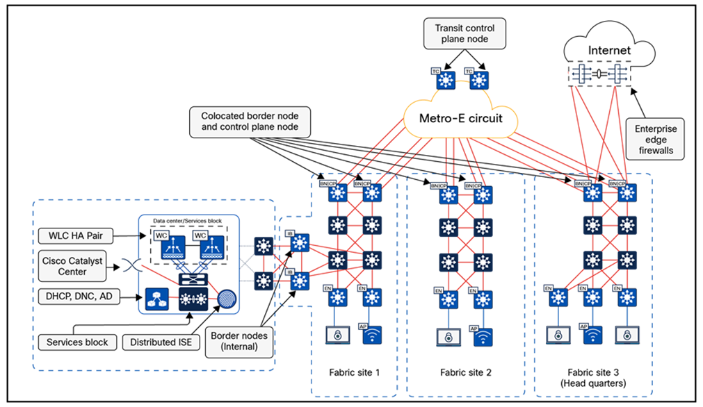
Distributed campus considerations:
● The core components enabling the distributed campus solution are the SD-Access transit and the transit control plane nodes. These architectural constructs are used exclusively in distributed campus deployments. The SD-Access transit serves as the physical network connection between fabric sites within the same city, on the same WAN, or across buildings in a large enterprise campus.
Tech tip: For wide-area deployment using a standard 1500-byte MTU, you can configure a smaller tcp adjust‑mss value such as 1250 on the client and AP-facing SVIs. If the UDP application uses an MTU value larger than the tcp adjust-mss value, adjust the MTU value on the UDP application server. We also recommend that you permit ICMP Type 3, Code 4 end-to-end throughout the network to allow requisite application control communication to take place for non-TCP MTU reduction.
Wireless design
Designing wireless solutions within Cisco's SD-Access framework in a university setting involves configuring and integrating multiple components to ensure seamless operation and management. Universities implementing an SD-Access fabric for their wired network have two options for incorporating wireless access:
● SD-Access wireless architecture
● Cisco Unified Wireless Network Wireless Over-the-Top
SD-Access wireless architecture
Cisco SD-Access provides a unique differentiator by integrating the wireless control plane with the overlay control plane of the wired world. Cisco SD-Access wireless offers a centralized control and management plane via the wireless controller with a distributed data plane providing the best of both worlds: centralized and distributed wireless designs.
The wireless controller integrates with the control plane node, registering endpoints as they are onboarded and updating their location as they roam. This is the first instance where there is synergy between the wireless and the wired control planes. This unique integration of wired and wireless brings several benefits to network users and the operations teams that support them:
● Simplification:
Networks can have a single subnet for both wired and wireless clients.
● Consistency of policy:
Wired policies are extended to wireless traffic, with both enforced at the edge node.
● Improved performance:
Wireless roams are Layer 2 and do not require any form of anchoring.
● Distributed data plane:
Enables higher overall wireless throughput compared to centrally switched wireless architectures.
Figure 15 depicts the control plane and data plane traffic flow in Cisco SD-Access wireless
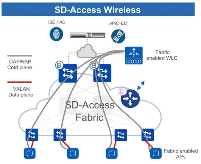
Cisco unified wireless network wireless over-the-top
Cisco SD-Access offers the flexibility to support a centralized wireless deployment known as wireless Over-the-Top (OTT). This support is crucial for several scenarios, such as:
● Existing Cisco wireless controllers and APs that are not SD-Access wireless-capable.
● Presence of third-party wireless devices in the network.
● Asymmetric migration pace between wired and wireless networks.
In wireless OTT deployments, wireless control, management, and data plane traffic travel through the fabric in a CAPWAP tunnel between the APs and wireless controller. This CAPWAP tunnel leverages the Cisco SD-Access fabric as a transport medium. While other vendors’ wireless equipment may use different tunnelling protocols, the concept of using the SD-Access fabric as a transport remains the same.
Figure 16 illustrates the flow of control plane and data plane traffic in wireless OTT.
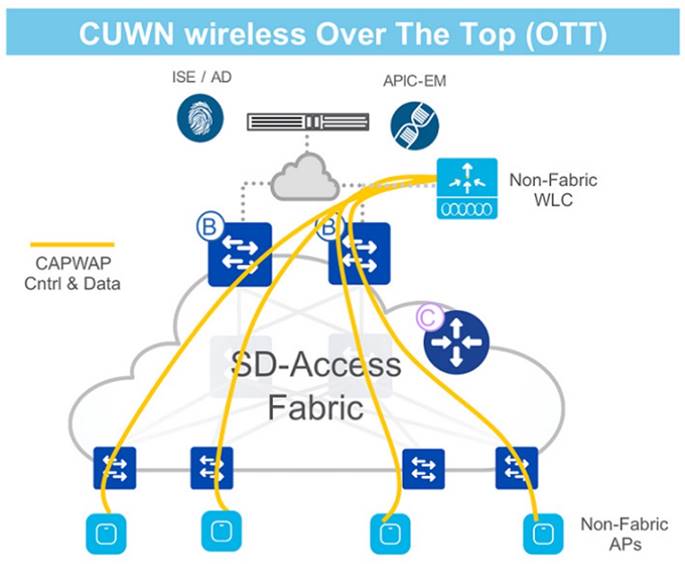
For more information, refer to the Cisco SD-Access Wireless Design and Cisco Wireless Design and Deployment Guide.
Multisite remote border
Multisite remote border (MSRB) centralizes the routing of untrusted traffic within the fabric network to a designated location such as a firewall or DMZ. For example, in a scenario where a guest VN spans multiple sites, all guest traffic can be directed through a remote border located at the DMZ, effectively isolating it from enterprise traffic.
In a multisite network deployment, a designated MSRB manages traffic to and from a specific VN extended across multiple sites. This configuration enables the deployment of a VN across multiple fabric sites while maintaining a unified subnet across these locations. Consistently maintaining subnets across multiple fabric sites helps optimize IP address use. It establishes a centralized entry and exit point for that VN, providing several advantages:
● Centralized control:
You can designate a common border switch, called the anchor border, to handle all traffic for a particular VN across various sites. This simplifies management and policy enforcement.
● Subnet consistency:
Multisite remote border enables you to use the same subnet for the VN across all sites. This eliminates the need to manage different subnets at each location, saving IP address space and simplifying configuration.
● Traffic isolation:
MSRB is particularly useful for isolating untrusted traffic, such as guest Wi-Fi. All guest traffic across different sites can be tunneled to a central location, like a DMZ, for security purposes.
Here are some common terms that are used in the context of a MSRB:
● Anchor VN:
A VN that exists across multiple fabric sites in a network. The associated IP subnet and segment are common across these multiple sites.
● Anchor site:
The fabric site that hosts the common border and control plane for an anchor VN. The anchor site handles the ingress and egress traffic for the anchor VN.
● Anchoring sites:
Fabric sites other than the anchor site where the anchor VN is deployed.
● Anchor border node or MSRB:
The fabric border node at the anchor site that provides the ingress and egress location for traffic to and from the anchor VN.
● Anchor control plane node:
The fabric control plane node at the anchor site that accepts registrations and responds to requests for endpoints in the anchor VN.
In essence, MSRB simplifies network management, enhances security for isolated traffic, and optimizes IP address usage in Cisco SD-Access deployments with multiple sites.
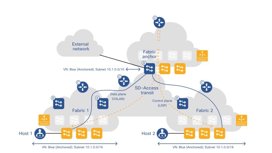
For more information, refer to the LISP VXLAN Fabric Configuration Guide.
Tech tip: It is crucial to consider the maximum transmission unit (MTU) across the entire path to accommodate the additional 50-byte VXLAN header overhead. This is particularly important as the reachability of the anchor site border node may involve traversing multiple IP networks.
LISP Publish and Subscribe design
LISP Publish and Subscribe (Pub/Sub) model is a significant enhancement to traditional LISP architecture. It streamlines the distribution of endpoint location information across the network, ensuring that all nodes receive timely and accurate data. With its efficiency, scalability, and ability to manage dynamic environments, the LISP Pub/Sub model is a crucial component in modern, large-scale network designs.
LISP Pub/Sub design eliminates the need for an additional protocol to register the LISP site registration table to control plane nodes in the fabric. LISP Pub/Sub feature is fully automated through Catalyst Center, which simplifies the deployment of an SD-Access fabric and removes the need for manual routing configuration.
LISP Pub/Sub architecture is a building block for other features and capabilities, such as:
● LISP dynamic default border node
● LISP backup internet
● LISP affinity-ID
● LISP extranet
LISP Pub/Sub uses a publish and subscribe model for routing information. Edge nodes subscribe to the default route, which includes the next-hop IP addresses of both border nodes. If a border node loses its upstream connection (and BGP peering), the default route is removed from the routing table for the affected VNs. The border node then updates the control plane to signal that it can no longer serve as the default route. As a result, the control plane informs all edge nodes subscribed to the default route, ensuring they stop using the failed route and instead rely on the default route toward the remaining active border node. This approach eliminates the need for BGP peering per VRF/VN between border nodes to maintain routing redundancy, thereby reducing manual configuration.
Deployment considerations:
● LISP/BGP fabric sites and LISP Pub/Sub fabric sites cannot co-exist with the same SD-Access Transit Control Plane Nodes.
● Migration from one to another is not supported yet,
● LISP Pub/Sub is recommended only for new network implementations.
For guidelines and recommendations on building a new greenfield deployment of an SD-Access fabric that addresses the challenges and use cases of a finance network, these sections explain the SD‑Access fabric components and the benefits SD-Access solutions offer in addressing ITES requirements and challenges.
Greenfield SD-Access networks can be established by incorporating infrastructure components, interconnecting them, and using Cisco Catalyst Center along with Cisco PnP and LAN automation to automate the provisioning of the network architecture from scratch. However, migrating to an existing network requires additional planning.
Some key considerations include:
● Does the network require reconfiguration into a Layer 3 routed access model?
● Do the components in the network support the desired scale for the target SD-Access topologies, or do the hardware platforms and software need to be upgraded?
● Is the organization ready for changes in IP addressing and DHCP scope management?
● What is the strategy for integrating new overlays with common services (for example: internet, DNS/DHCP, data center applications)?
● Are SGTs or dynamic ACLs already implemented, and where are the policy enforcement points? If SGTs and multiple overlays are used to segment and virtualize within the fabric, what requirements exist for extending them beyond the fabric? Is infrastructure in place to support Cisco TrustSec, VRF-lite, MPLS, or other technologies necessary to extend and support the segmentation and virtualization?
● Can wireless coverage within a roaming domain be upgraded at a single point in time, or does the network need to rely on over-the-top strategies?
Migration strategies
There are three main approaches for migrating an existing network to SD-Access:
● Parallel:
In this approach, an SD-Access network is established alongside the existing brownfield network. Switches are transferred from the brownfield network to the SD-Access network by physically connecting cables. This method simplifies change management and rollback. However, it requires additional rack space, power, and cabling infrastructure beyond the current setup of the brownfield network.
● Incremental:
This strategy involves migrating a traditional switch from the brownfield network and converting it into an SD-Access fabric edge node. The Layer 2 border handoff, discussed later, facilitates this gradual migration. This approach is ideal for networks with existing equipment that can support SD-Access or for environments with constraints like limited space and power.
● Hybrid:
The hybrid approach combines elements of both the parallel and incremental strategies. For instance, a new pair of core switches is configured as border nodes, control plane nodes are added and configured, and the brownfield access switches are progressively converted into SD-Access fabric edge nodes.
For complete guidance and different options to migrate existing traditional networks to Cisco SD-Access, refer to the “Migration to Cisco SD-Access” chapter in the Cisco Software-Defined Access for Industry Verticals.
Fabric wireless migration
Imagine a sample network within a building consisting of two floors, with its SSID managed by a wireless controller on campus. When migrating to fabric wireless, it is important to understand that seamless roaming will not be available between the existing SSID and the fabric SSID to which users will be migrated. APs connect to access switches and establish CAPWAP tunnels to the centralized wireless controller, handling all wireless management, control, and data traffic.
To integrate wireless into the Cisco SD-Access fabric, start by creating a wired fabric within the existing building network. The wired fabric can be deployed using any of the standard models described earlier: parallel, incremental, or hybrid. Once the access switch to which the AP is connected becomes a fabric edge, users can still connect to the existing SSID and be centrally switched. This allows the wireless network to function over the fabric without significantly impacting existing wireless services during the wired network migration.
A brownfield wireless controller is supported when transitioning to fabric, but it must comply with the SD‑Access compatibility matrix regarding Cisco IOS XE images and platforms. When discovered via Cisco Catalyst Center, the system will recognize the wireless controller’s existing configuration without modifying it.
The migration to fabric wireless can be performed in phases, with the smallest migration unit being a floor within the site hierarchy. Administrators can also migrate an entire building or area, depending on the environment. By creating a wireless network profile, configuring the SSID as fabric-enabled, and assigning it to a specific floor, you can gradually transition the existing SSID from OTT to fabric‑enabled. This phased approach ensures a smooth and controlled migration. When all floors, buildings, or areas are mapped to the fabric-based SSID, the transition to fabric-enabled wireless is complete, at which point segmentation policies can be defined.
A key consideration during migration is the lack of seamless roaming between SSIDs operating in OTT mode and those in fabric mode. It is crucial to define an IP pool that does not overlap with the OTT SSID during the transition. If you have an existing wireless controller, you can reuse it to manage both a fabric site and traditional wireless networks. However, after a wireless controller is converted to manage a fabric site, it can oversee only a single fabric site alongside multiple traditional wireless sites.
Layer 2 border handoff
The Layer 2 border handoff facilitates seamless communication between an SD-Access network and a traditional network by providing an overlay service that allows hosts in both environments to interact as if they were on the same Layer 2 domain. This feature is crucial when transitioning from a traditional network to an SD-Access network. It enables endpoints in the traditional network to remain in place while connectivity with SD-Access endpoints is tested, without requiring re-IP addressing. Migration can then proceed either through a parallel approach, which involves physically relocating cables, or an incremental method by converting a traditional access switch into an SD-Access fabric edge node.
With the Layer 2 border handoff, both the fabric site and the traditional network VLAN segment can share the same subnet. Communication is facilitated through a border node that performs VLAN translation or VLAN extension between the fabric and non-fabric environments. Cisco Catalyst Center automates the LISP control plane configuration, VLAN translation, SVI setup, and trunk port connections to the traditional network on the border node.
Multicast traffic is supported across the Layer 2 handoff, ensuring multicast communication between the traditional and SD-Access networks. The multicast forwarding mechanism functions consistently across the Layer 2 border node, just as it does within the fabric. Meanwhile, the traditional network continues to handle multicast packets using standard Layer 2 flooding techniques.
For operational technology (OT), Internet of Things (IoT), and building management systems (BMS) migrating to SD-Access, the Layer 2 border handoff can be combined with Layer 2 flooding. This supports Ethernet broadcast-based wake-on-LAN functionality between the fabric site and the traditional network, enabling OT and BMS systems (typically reliant on broadcast communication) to transition gradually into the fabric.
Deployment models and topology
The traditional network switches can be connected to a single border node with a Layer 2 handoff. A traditional network switch should not be multihomed to multiple border nodes. Dual homing, however, is supported using link aggregation. Multichassis EtherChannel (MEC) is supported to a single border if the traditional network switches are operating in a multibox, single logical box construct such as a hardware switch stack or SVL. Redundancy for the border node itself can be provided through hardware stacking or SVL.
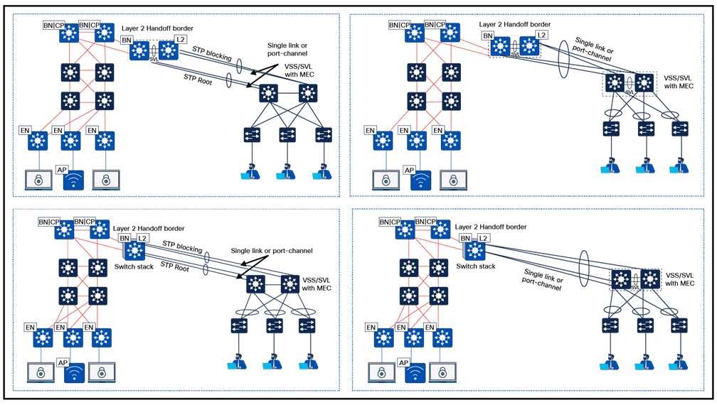
Virtual private network for offshore development center deployment
For a secure ODC in an ITES organization, a reliable Virtual Private Network (VPN) is crucial for safe connectivity between remote teams, data centers, and client networks. It encrypts data to safeguard against cyber threats and ensures compliance with security regulations. Depending on the requirements, an ITES organization chooses from these VPN types:
● Site-to-site VPN
● Client-to-site VPN
Site-to-site VPN
Site-to-site VPN is a type of VPN setup that creates a secure connection between two or more geographically separate offices or physical locations of the same organization. This connection, often referred to as a VPN tunnel, allows for the secure transmission of data and resources across a public network, such as the internet, as if the sites were connected by a private network.
The site-to-site VPN is typically established between network gateways, such as routers or firewalls, that are configured to encrypt and decrypt traffic entering and exiting the sites. This setup is commonly used by businesses to ensure that communication between their offices is secure and cannot be intercepted by unauthorized parties.
Client-to-site VPN
Client-to-site VPN, also known as a Remote Access VPN, is a type of VPN that allows individual users to connect to a remote network, such as their workplace's network, from any location. This is achieved through VPN client software installed on the user's device, which establishes a secure connection to the VPN server located at the remote site.
When connected, the user's device becomes a part of the remote network, allowing access to network resources as if the user were physically present within the network's local environment. This type of VPN is commonly used by remote workers, travelers, or anyone needing secure access to their organization's network from an external location.
In summary, both site-to-site and client-to-site VPNs use encryption and other security mechanisms to ensure that data transmitted over the public internet remains confidential and protected from unauthorized access.
Validated solution use cases
These sections describe some of the important use cases validated for ITES that serve as trusted templates, empowering organizations to build their IT infrastructure, ensuring that these designs have undergone thorough testing and are customized to meet their specific business needs.
Day-zero and day-1 network bring up use cases
● Bring up network infrastructure and integrate all features for greenfield campus.
● Automate and simplify network device and fabric provisioning.
● Monitor inventory and manage network devices using Catalyst Center.
● Integrate with Cisco ISE for authentication and authorization of device and client.
● Manage and deploy wireless controllers and APs using Catalyst Center.
● Onboard devices via plug and play for network devices and APs.
● Manage network settings for multiple sites using Cisco Catalyst for shared services.
● Deploy SD-Access multisite campus and manage traffic across campus.
Day-n network operations use cases
● Upgrade multiple devices, such as switches, routers, and wireless controllers using Catalyst Center.
● Onboard new floors to existing fabric sites.
● Onboard new fabric nodes with wired and wireless clients.
● Replace brownfield APs from Wave2 to 11 Ax.
● Add small new sites using FIAB with an embedded wireless controller.
● Add small new fabric sites with another Flex OTT deployment.
● Do day-n credential changes such as, device password changes and network device updates.
● Allow VLAN on the Layer 2 and Layer 3 handoff link using a template.
Tech tip: The template must be reprovisioned after any operation that triggers the "switchport mode trunk" and “switchport trunk allowed vlan all” configuration for the uplink port.
Segmentation and policy use cases
● Implement virtual networks across the organization to achieve consistent macro segmentation.
● Use group-based access policy for micro segmentation within a virtual network using SGTs.
● Ensure secure onboarding of wired and wireless clients using authentication.
● Enforce policy at different entry and exit traffic points in the fabric.
● Operational scenarios that include the addition of new segments and group-based access policies for devices and users.
Security use cases
● Apply and use trusted CA FQDN-based certificates with Catalyst Center.
● Create granular role-based users with external AAA authentication and use audit logging to check Catalyst Center activities.
● Monitor audit policy changes, deployment of policy changes, and status of these deployments.
SD-Access wireless use cases
● Onboard wireless clients using enterprise SSID for branch employees and users.
● Provide guest wireless access for users at branches using a CWA portal.
● Deploy wireless infrastructure with Catalyst 9800 Series Wireless Controller in HA mode and an embedded wireless LAN controller.
● Enforce guest SSID traffic policies on the firewall using multisite remote border.
Robustness use cases
● Recovery from device or link failure automatically with minimal impact on existing applications, traffic, and users.
● Catalyst Center in three-node HA mode. In case of services or node failure in Catalyst Center, the system should recover without user intervention.
● Cisco ISE distributed nodes failover with PSN, pxGrid node failover.
● Cisco Catalyst wireless LAN controller and APs failover.
● Failover scenarios with link and network device failure within the fabric.
● Back up Catalyst Center controller configuration and data either, one time or on schedule.
● Restore backup on a new Cisco Catalyst cluster and verify the ability to manage the devices.
● Longevity with churn in the network, policy, and device connectivity.
Monitoring and troubleshooting with assurance and analytics use cases
● Monitor the state of the network, wired users, and wireless users from a unified interface.
● Monitor severe, critical, and other ongoing issues with the network and devices and follow the suggested actions in assurance to resolve the issues.
● Obtain a comprehensive view of individual devices, wired user, or wireless user and retrieve detailed information.
● Track detailed application data usage by users using application visibility.
Performance and scale use cases
● Multi-dimensional scale configuration with all solutions integrated and check for stability of the network.
ITES ODC deployment models
Site-to-site ODC with a dedicated firewall and gateway outside the fabric
Business requirements:
● Establish an ODC using Cisco SD-Access.
● Ensure that all traffic transits through the firewall and is logged for auditing and compliance.
● Ensure secure data transfer between networks.
● Restrict ODC users' access to systems within their respective ODC.
● Implement a dedicated firewall for the ODC.
Technical requirements:
● Provision the Cisco SD-Access network using Catalyst Center.
● Implement Layer 2 VNs with a gateway outside of the fabric.
● Configure a site-to-site VPN for secure data transfer.
● Use macro (VN) or micro (SGT) segmentation to isolate ODC users and systems.
● Configure the firewall interface to manage traffic from the dedicated ODC.
Procedure 1.
Step 1. Using an appropriate VLAN ID, configure a Layer 2 VN and then assign it to a site.
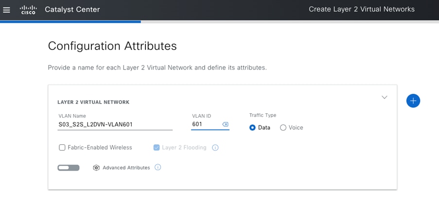
Step 2. Configure Layer 2 handoff on the dedicated border node. Enable the VLANs that you can access from the Layer 2 VNs with a gateway outside of the fabric.
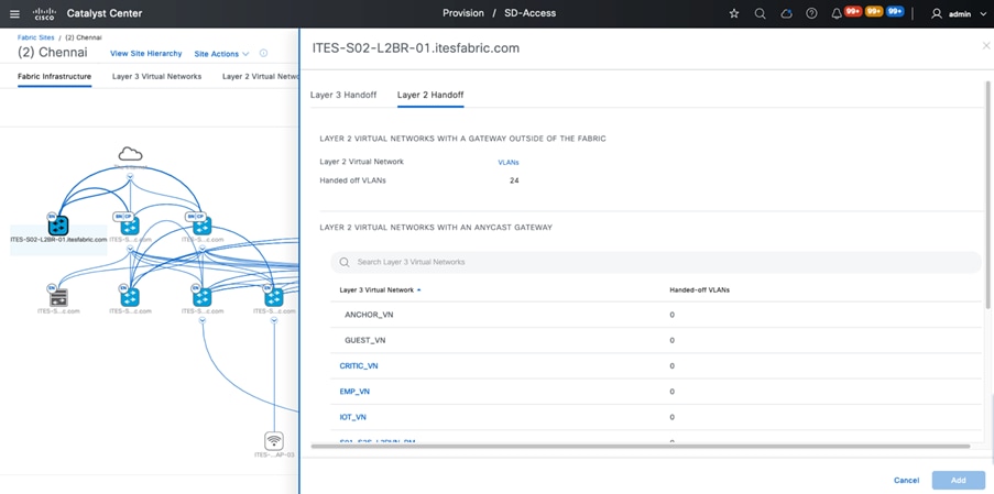
Tech tip: The uplink port on the Layer 2 border node facing the firewall is configured as a trunk, either as a standalone interface or part of a port channel.
Step 3. Enable end-to-end communication on the firewall. At a minimum, you'll need to configure these items:
- Inside interface (specifying a physical interface or subinterface as the ODC’s client gateway)
- Outside interface
- Firewall policies
- Routing for reachability
- Site-to-Site VPN
Step 4. Configure Cisco ISE to ensure proper authentication and authorization for both ODC and corporate users.
Step 5. If the allow-list (default deny IP) is enabled, choose one of these options. Also, ensure that the correct policy matrix is configured for the source and destination security tags.
- Establish an SXP session between Cisco ISE and the Layer 2 border node to obtain the destination addresses security tags.
- Manually configure the subnet-to-SGT mapping.
Step 6. After authentication completes successfully, the end user should have access to all authorized resources.
After a successful deployment, the traffic flow between the ODC and the client’s network can be seen in Figure 21.
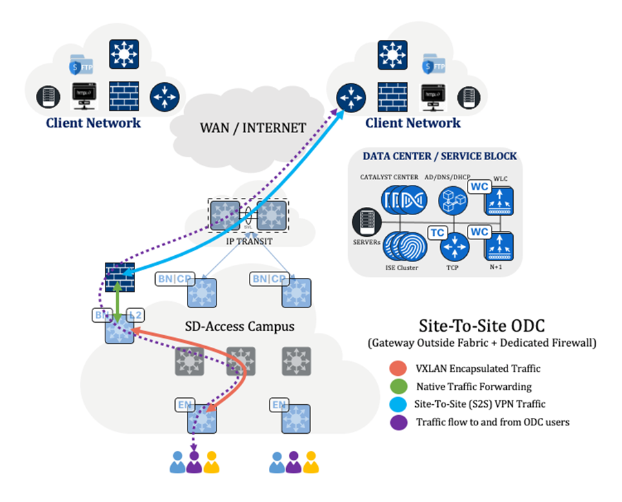
Note: Refer to the legend and arrows, which indicate the flow of traffic.
Site-to-site ODC with a shared firewall and gateway outside the fabric
Business requirements:
● Establish an ODC using Cisco SD-Access.
● Ensure that all traffic transits through the firewall and is logged for auditing and compliance.
● Ensure secure data transfer between networks.
● Restrict ODC users' access to systems within their respective ODC.
● Use the same firewall for multiple ODCs.
Technical requirements:
● Provision the Cisco SD-Access network using Catalyst Center.
● Implement Layer 2 VNs with a gateway outside of the fabric.
● Configure a site-to-site VPN for secure data transfer.
● Use macro (VN) or micro (SGT) segmentation to isolate ODC users and systems.
● Configure the firewall interface to handle traffic from each ODC separately.
Procedure 2.
Step 1. Using an appropriate VLAN ID, configure a Layer 2 VN and then assign it to a site.
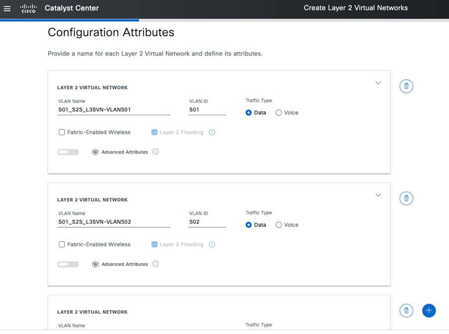
Step 2. Configure Layer 2 handoff on the dedicated border node. Enable the VLANs that you can access from the Layer 2 VNs with a gateway outside of the fabric area.
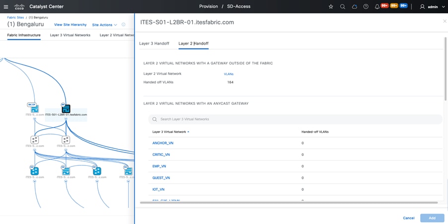
Step 3. Enable end-to-end communication on the firewall. At a minimum, you'll need to configure these items:
- Inside interface (specifying a physical interface or subinterface as the ODC’s client gateway).
- Outside interface
- Firewall policies
- Routing for reachability
- Site-to-site VPN
Step 4. Configure Cisco ISE to ensure proper authentication and authorization for both ODC and corporate users.
Step 5. If the allow-list (default deny IP) is enabled, choose one of these options. Also, ensure that the correct policy matrix is configured for the source and destination security tags.
- Establish an SXP session between Cisco ISE and the Layer 2 border node to obtain the destination addresses security tags.
- Manually configure the subnet-to-SGT mapping.
Step 6. After authentication completes successfully, the end user should have access to all authorized resources.
After a successful deployment, the traffic flow between the ODC and the client’s network can be seen in Figure 24.
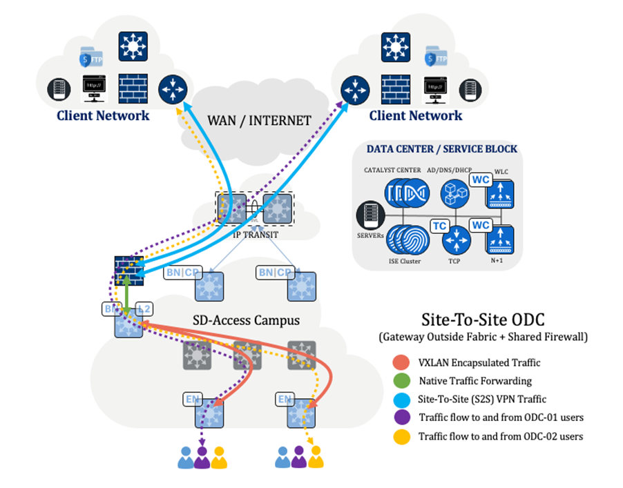
Note: Refer to the legend and arrows, which indicate the flow of traffic.
Client-to-site ODC with a dedicated firewall and gateway outside the fabric
Business requirements:
● Establish an ODC using Cisco SD-Access.
● Set up a firewall to act as the client’s gateway and log all traffic for auditing and compliance.
● Use a VPN client to securely connect to the client network.
● Restrict ODC users' access to systems within their respective ODC.
● Implement a dedicated firewall for the ODC.
Technical requirements:
● Provision the Cisco SD-Access network using Catalyst Center.
● Implement Layer 2 VNs with a gateway outside of the fabric.
● Install and configure a VPN client on ODC users' laptops and desktops.
● Use macro (VN) or micro (SGT) segmentation to isolate ODC users and systems.
● Configure the firewall to manage traffic from the dedicated ODC.
Procedure 3.
Step 1. Using an appropriate VLAN ID, configure a Layer 2 VN and then assign it to a site.
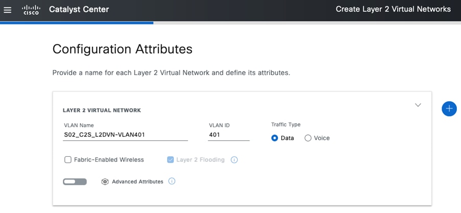
Step 2. Configure a Layer 2 handoff on the dedicated border node. Enable the VLANs that you can access from the Layer 2 VN with a gateway outside of the fabric area.
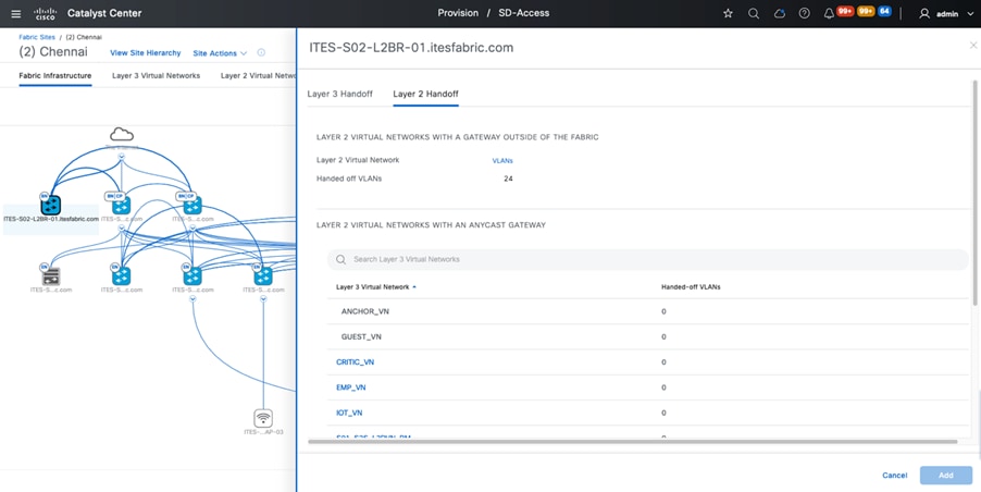
Tech tip: The uplink port on the Layer 2 border node facing the firewall is configured as a trunk, either as a standalone interface or part of a port channel.
Step 3. Enable end-to-end communication on the firewall. At a minimum, you'll need to configure these items:
- Inside interface (specifying a physical interface or subinterface as the ODC’s client gateway)
- Outside interface
- Firewall policies
- Routing for reachability
Step 4. Configure Cisco ISE to ensure proper authentication and authorization for both ODC and corporate users.
Step 5. If the allow-list (default deny IP) is enabled, choose one of these options. Also, ensure that the correct policy matrix is configured for the source and destination security tags:
- Establish an SXP session between Cisco ISE and the Layer 2 border node to obtain the destination addresses security tags.
- Manually configure the subnet-to-SGT mapping.
Step 6. After authentication completes successfully, the end user should have access to all authorized resources.
After a successful deployment, the traffic flow between the ODC and the client’s network can be seen in Figure 27.
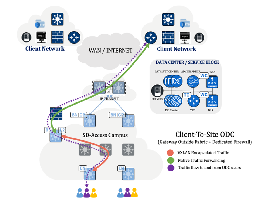
Note: Refer to the legend and arrows, which indicate the flow of traffic.
Client-to-site ODC with a shared firewall and gateway outside of the fabric
Business requirements:
● Establish an ODC using Cisco SD-Access.
● Set up a firewall to act as the client’s gateway and log all traffic for auditing and compliance.
● Use a VPN client to securely connect to the client network.
● Restrict ODC users' access to systems within their respective ODC.
● Use the same firewall for multiple ODCs.
Technical requirements:
● Provision the Cisco SD-Access network using Catalyst Center.
● Implement Layer 2 VNs with a gateway outside of the fabric.
● Install and configure a VPN client on ODC users' laptops and desktops.
● Use macro (VN) or micro (SGT) segmentation to isolate ODC users and systems.
● Configure the firewall interface to handle traffic from each ODC separately.
Procedure 4.
Step 1. Using an appropriate VLAN ID, configure a Layer 2 VN and then assign it to a site.
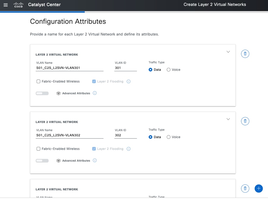
Step 2. Configure a Layer 2 handoff on the dedicated border node. Enable the VLANs that you can access from the Layer 2 VN with a gateway outside of the fabric area.
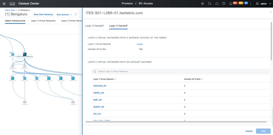
Tech tip: The uplink port on the Layer 2 border node facing the firewall is configured as a trunk, either as a standalone interface or part of a port channel.
Step 3. Enable end-to-end communication on the firewall. At a minimum, you'll need to configure these items:
- Inside interface (specifying a physical interface or subinterface as the ODC’s client gateway)
- Outside interface
- Firewall policies
- Routing for reachability
Step 4. Configure Cisco ISE to ensure proper authentication and authorization for both ODC and corporate users.
Step 5. If the allow-list (default deny IP) is enabled, choose one of these options. Also, ensure that the correct policy matrix is configured for the source and destination security tags.
- Establish an SXP session between Cisco ISE and the Layer 2 border node to obtain the destination addresses' security tags.
- Manually configure the subnet-to-SGT mapping.
Step 6. After authentication completes successfully, the end user should have access to all authorized resources.
After a successful deployment, the traffic flow between the ODC and the client’s network can be seen in Figure 30.
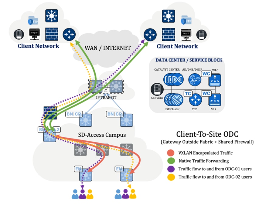
Note: Refer to the legend and arrows, which indicate the flow of traffic.
Site-to-site ODC with a dedicated firewall and anycast gateway
Business requirements:
● Establish an ODC using Cisco SD-Access.
● Ensure that all traffic transits through the firewall and is logged for auditing and compliance.
● Ensure the secure transfer of data between networks.
● Restrict ODC users' access to systems within their respective ODC.
● Implement a dedicated firewall for the ODC.
Technical requirements:
● Provision the Cisco SD-Access network using Catalyst Center.
● Redirect all traffic from the fusion device to the firewall and then forward it to the destination.
● Configure a site-to-site VPN for secure data transfer.
● Use macro (VN) or micro (SGT) segmentation to isolate ODC users and systems.
● Configure the firewall interface to manage traffic from the dedicated ODC.
Procedure 5.
Step 1. Configure a Layer 3 VN at the site and then provision the required anycast gateway.
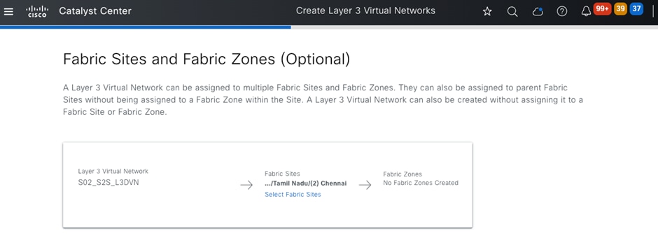
Step 2. Configure Layer 3 handoff on the border nodes for the newly added VN, then ensure that the eBGP sessions are up.
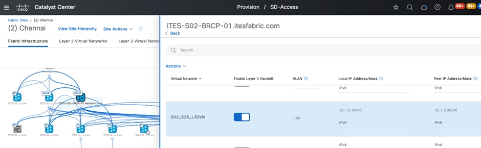
Step 3. Enable end-to-end communication on the firewall. At a minimum, you'll need to configure these items:
- Inside interface (specifying a physical interface or subinterface as the ODC’s client gateway)
- Outside interface
- Firewall policies
- Routing for reachability
- Site-to-site VPN
Step 4. Configure Cisco ISE to ensure proper authentication and authorization for both ODC and corporate users.
Step 5. If the allow-list (Default Deny IP) is enabled, choose one of these options. Also, ensure that the correct policy matrix is configured for the source and destination security tags.
- Establish a VRF-aware SXP session between Cisco ISE and the VN's Layer 3 border node to obtain the destination addresses' security tags.
- Manually configure the subnet-to-SGT mapping.
Note: Configure the VN traffic that traverses the firewall to allow TCP bypass specifically for SXP communications between the Cisco ISE server and Layer 3 border nodes.
Step 6. After authentication completes successfully, the end user should have access to all authorized resources.
After a successful deployment, the traffic flow between the ODC and the client’s network can be seen in Figure 33.
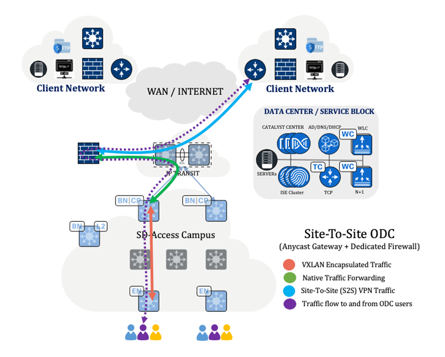
Note: Refer to the legend and arrows, which indicate the flow of traffic.
Site-to-site ODC with a shared firewall and anycast gateway
Business requirements:
● Establish an ODC using Cisco SD-Access.
● Ensure that all traffic transits through the firewall and is logged for auditing and compliance.
● Ensure the secure transfer of data between networks.
● Restrict ODC users' access to systems within their respective ODC.
● Use the same firewall for multiple ODCs.
Technical requirements:
● Provision the Cisco SD-Access network using Catalyst Center.
● Redirect all traffic from the fusion device to the firewall and then forward it to the destination.
● Configure a site-to-site VPN for secure data transfer.
● Use macro (VN) or micro (SGT) segmentation to isolate ODC users and systems.
● Configure the firewall interface to handle traffic from each ODC individually.
Procedure 6.
Step 1. Configure a Layer 3 VN at the site and then provision the required anycast gateways.
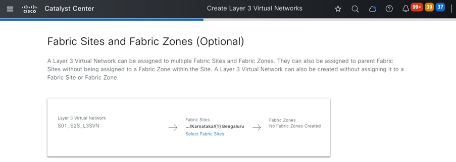
Step 2. Configure Layer 3 handoff on the border nodes for the newly added VN, then ensure that the eBGP sessions are up.
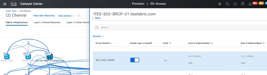
Step 3. Enable end-to-end communication on the firewall. At a minimum, you'll need to configure these items:
- Inside interface (specifying a physical interface or subinterface as the ODC’s client gateway)
- Outside interface
- Firewall policies
- Routing for reachability
- Site-to-site VPN
Step 4. Configure Cisco ISE to ensure proper authentication and authorization for both ODC and corporate users.
Step 5. If the allow-list (Default Deny IP) is enabled, choose one of these options. Also, ensure that the correct policy matrix is configured for the source and destination security tags.
- Establish a VRF-aware SXP session between Cisco ISE and the VN's Layer 3 border node to obtain the destination addresses' security tags.
- Manually configure the subnet-to-SGT mapping.
Note: Configure the VN traffic that traverses the firewall to allow TCP bypass specifically for SXP communications between the Cisco ISE server and Layer 3 border nodes.
Step 6. After authentication completes successfully, the end user should have access to all authorized resources.
After a successful deployment, the traffic flow between the ODC and the client’s network can be seen in Figure 36.
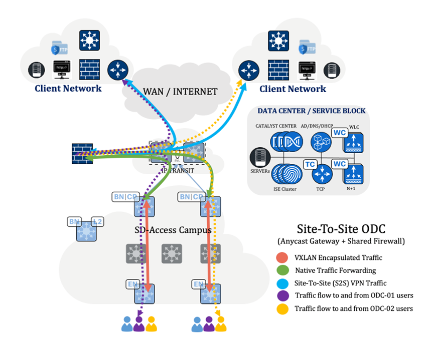
Note: Refer to the legend and arrows, which indicate the flow of traffic.
Client-to-site ODC with a dedicated firewall and anycast gateway
Business requirements:
● Establish an ODC using Cisco SD-Access.
● Ensure that all traffic transits through the firewall and is logged for auditing and compliance.
● Use a VPN client to securely connect to the client network.
● Restrict ODC users' access to systems within their respective ODC.
● Implement a dedicated firewall for the ODC.
Technical requirements:
● Provision the Cisco SD-Access network using Catalyst Center.
● Redirect all traffic from the fusion device to the firewall and then forward it to the destination.
● Install and configure a VPN client on ODC users' laptops and desktops.
● Use macro (VN) or micro (SGT) segmentation to isolate ODC users and systems.
● Configure the firewall interface to manage traffic from the dedicated ODC.
Procedure 7.
Step 1. Configure a Layer 3 VN at the site and then provision the required anycast gateway.
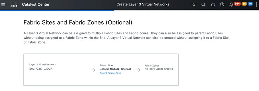
Step 2. Configure the Layer 3 handoff on the border nodes for the newly added VN, then ensure that the eBGP sessions are up.
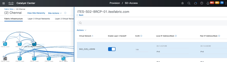
Step 3. Enable end-to-end communication on the firewall. At a minimum, you'll need to configure these items:
- Inside interface (specifying a physical interface or subinterface as the ODC’s client gateway)
- Outside interface
- Firewall policies
- Routing for reachability
Step 4. Configure Cisco ISE to ensure proper authentication and authorization for both ODC and corporate users.
Step 5. If the allow-list (Default Deny IP) is enabled, choose one of these options. Also, ensure that the correct policy matrix is configured for the source and destination security tags.
- Establish a VRF-aware SXP session between Cisco ISE and the VN's Layer 3 border node to obtain the destination addresses' security tags.
- Manually configure the subnet-to-SGT mapping.
Note: Configure the VN traffic that traverses the firewall to allow TCP bypass specifically for SXP communications between the Cisco ISE server and Layer 3 border nodes.
Step 6. After authentication completes successfully, the end user should have access to all authorized resources.
After a successful deployment, the traffic flow between the ODC and the client’s network can be seen in Figure 39.
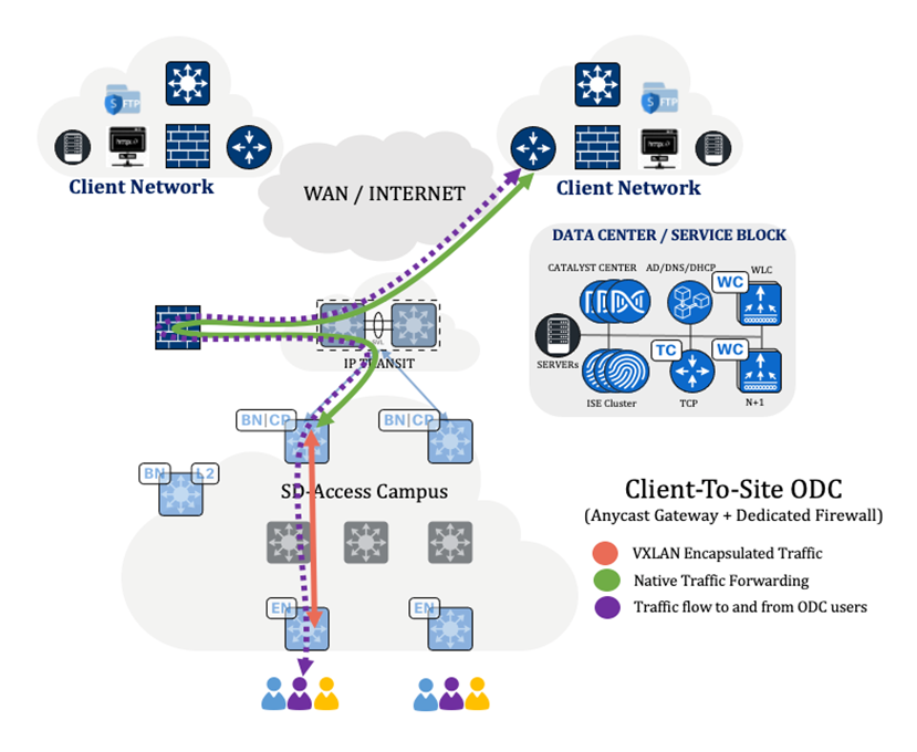
Note: Refer to the legend and arrows, which indicate the flow of traffic.
Client-to-Site ODC with a shared firewall and anycast gateway
Business requirements:
● Establish an ODC using Cisco SD-Access.
● Ensure that all traffic transits through the firewall and is logged for auditing and compliance.
● Use a VPN client to securely connect to the client network.
● Restrict ODC users' access to systems within their respective ODC.
● Use the same firewall for multiple ODCs.
Technical requirements:
● Provision the Cisco SD-Access network using Catalyst Center.
● Redirect all traffic from the fusion device to the firewall and then forward it to the destination.
● Install and configure a VPN client on ODC users' laptops and desktops.
● Use macro (VN) or micro (SGT) segmentation to isolate ODC users and systems.
● Configure the firewall interface to handle traffic from each ODC separately.
Procedure 8.
Step 1. Configure a Layer 3 VN at the site and then provision the required anycast gateway.
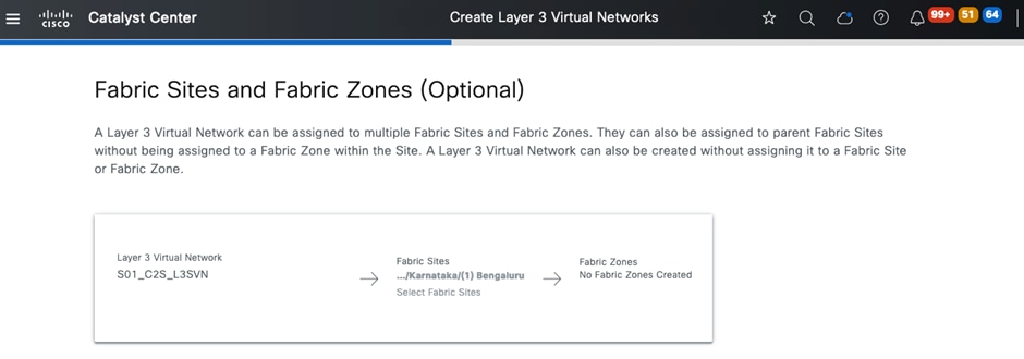
Step 2. Configure Layer 3 handoff on the border nodes for the newly added VN, then ensure that the eBGP sessions are up.
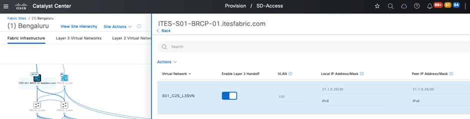
Step 3. Enable end-to-end communication on the firewall. At a minimum, you'll need to configure these items:
- Inside interface (specifying a physical interface or subinterface as the ODC’s client gateway)
- Outside interface
- Firewall policies
- Routing for reachability
- Site-to-Site VPN
Step 4. Configure Cisco ISE to ensure proper authentication and authorization for both ODC and corporate users.
Step 5. If the allow-list (Default Deny IP) is enabled, choose one of these options. Also, ensure that the correct policy matrix is configured for the source and destination security tags.
- Establish a VRF-aware SXP session between Cisco ISE and the VN's Layer 3 border node to obtain the destination addresses' security tags.
- Manually configure the subnet-to-SGT mapping.
Note: Configure the VN traffic that traverses the firewall to allow TCP bypass specifically for SXP communications between the Cisco ISE server and Layer 3 border nodes.
Step 6. After authentication completes successfully, the end user should have access to all authorized resources.
After a successful deployment, the traffic flow between the ODC and the client’s network can be seen in Figure 42.
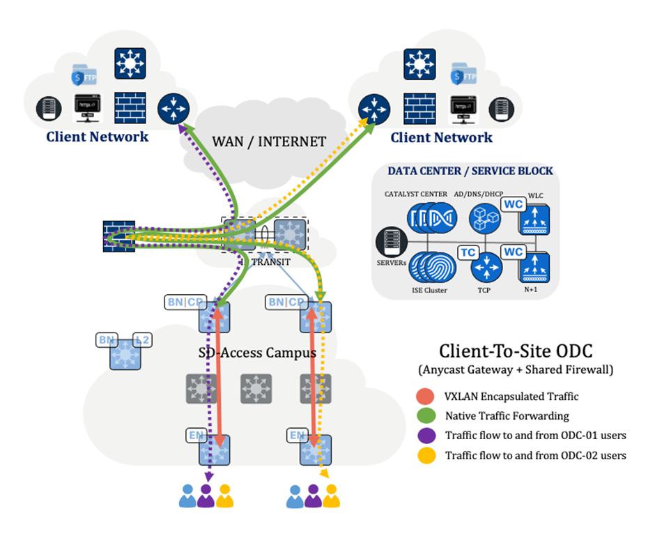
Note: Refer to the legend and arrows, which indicate the flow of traffic.
Site-to-site ODC with a dedicated firewall connected to the edge and acting as a gateway
Business requirements:
● Establish an ODC using Cisco SD-Access.
● Set up a firewall to act as the client’s gateway and log all traffic for auditing and compliance.
● Confirm that the dedicated firewall is directly connected to the fabric edge node.
● Ensure the secure transfer of data between networks.
● Restrict ODC users' access to systems within their respective ODC.
● Implement a dedicated firewall for the ODC.
Technical requirements:
● Provision the Cisco SD-Access network using Catalyst Center.
● Provision a Layer 2 VN and add it to the fabric zone.
● Ensure that all ODC users and systems, as well as the firewall, are connected on the edge node within the fabric zone. The port connected to the firewall must be configured as a trunk port.
● Configure a site-to-site VPN for secure data transfer.
● Use macro (VN) or micro (SGT) segmentation to isolate ODC users and systems.
● Configure the firewall interface to manage traffic from the dedicated ODC.
Procedure 9.
Step 1. Enable the fabric zone for the site, where the ODC users, systems, and firewall are connected to the edge node.
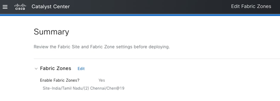
Step 2. Create a Layer 2 VN with an appropriate VLAN ID. Then assign the VN to both the fabric site and fabric zone.
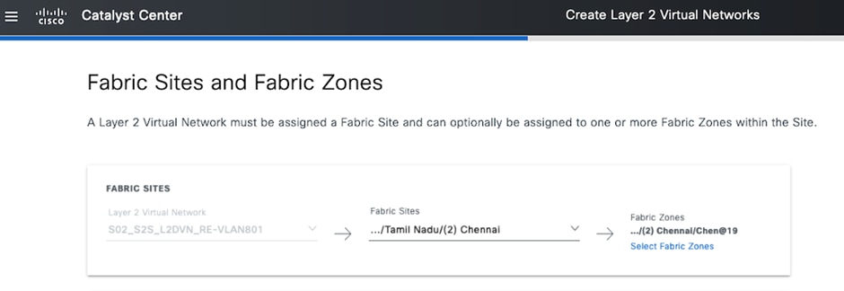
Step 3. Configure the port connected to the firewall on the edge node as a trunk port.
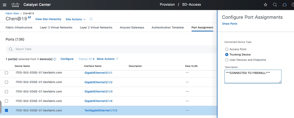
Step 4. Enable end-to-end communication on the firewall. At a minimum, you'll need to configure these items:
- Inside interface (specifying a physical interface or subinterface as the ODC’s client gateway)
- Outside interface
- Firewall policies
- Routing for reachability
- Site-to-site VPN
Step 5. Configure Cisco ISE to ensure proper authentication and authorization for both ODC and corporate users.
Step 6. If the allow-list (default deny IP) is enabled, choose one of these options. Also, ensure that the correct policy matrix is configured for the source and destination security tags.
- Establish a VRF-aware SXP session between Cisco ISE and the VN's Layer 3 border node to obtain the destination addresses' security tags.
- Manually configure the subnet-to-SGT mapping
Note: Configure the VN traffic that traverses the firewall to allow TCP bypass specifically for SXP communications between the Cisco ISE server and Layer 3 border nodes.
Step 7. After authentication completes successfully, the end user should have access to all authorized resources.
After a successful deployment, the traffic flow between the ODC and the client’s network can be seen in Figure 46.
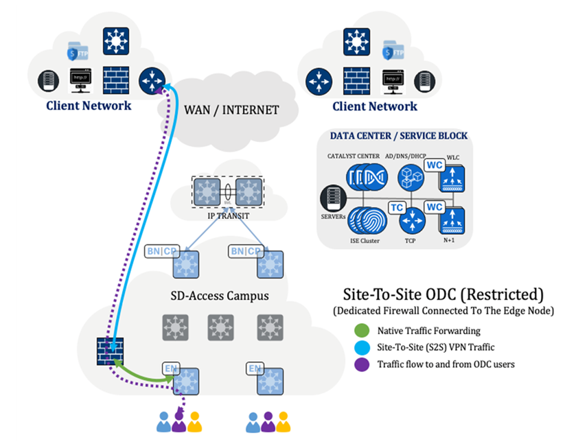
Note: Refer to the legend and arrows, which indicate the flow of traffic.
Client-to-site ODC with a dedicated firewall connected to the edge and acting as gateway
Business requirements:
● Establish an ODC using Cisco SD-Access.
● Ensure the dedicated firewall is directly connected to the fabric edge node.
● Set up a firewall to act as the client’s gateway and log all traffic for auditing and compliance.
● Use a VPN client to securely connect to the client network.
● Restrict ODC users' access to systems within their respective ODC.
● Implement a dedicated firewall for the ODC.
Technical requirements:
● Provision the Cisco SD-Access network using Catalyst Center.
● Provision a Layer 2 VN and add it to the fabric zone.
● Ensure that all ODC users, systems, and the firewall are connected to the edge node within the fabric zone. The port connected to the firewall must be configured as a trunk port.
● Install and configure a VPN client on ODC users' laptops and desktops.
● Use macro (VN) or micro (SGT) segmentation to isolate ODC users and systems.
● Configure the firewall to manage traffic from the dedicated ODC.
Procedure 10.
Step 1. Enable the fabric zone for the site, where ODC users, systems, and the firewall are connected to the edge node.
Step 2. Create a Layer 2 VN with an appropriate VLAN ID. Then assign the VN to both the fabric site and fabric zone.
Step 3. Configure the port connected to the firewall on the edge node as a trunk port.
Step 4. Enable end-to-end communication on the firewall. At a minimum, you'll need to configure these items:
- Inside interface (specifying a physical interface or subinterface as the ODC’s client gateway)
- Outside interface
- Firewall policies
- Routing for reachability
Step 5. Configure Cisco ISE to ensure proper authentication and authorization for both ODC and corporate users.
Step 6. If the allow-list (Default Deny IP) is enabled, choose one of the following options. Also, ensure that the correct policy matrix is configured for the source and destination security tags.
- Establish a VRF-aware SXP session between Cisco ISE and the VN's Layer 3 border node to obtain the destination addresses' security tags.
- Manually configure the subnet-to-SGT mapping.
Note: Configure the VN traffic that traverses the firewall to allow TCP bypass specifically for SXP communications between the Cisco ISE server and Layer 3 border nodes.
Step 7. After authentication completes successfully, the end user should have access to all authorized resources.
After a successful deployment, the traffic flow between the ODC and the client’s network can be seen in Figure 50.
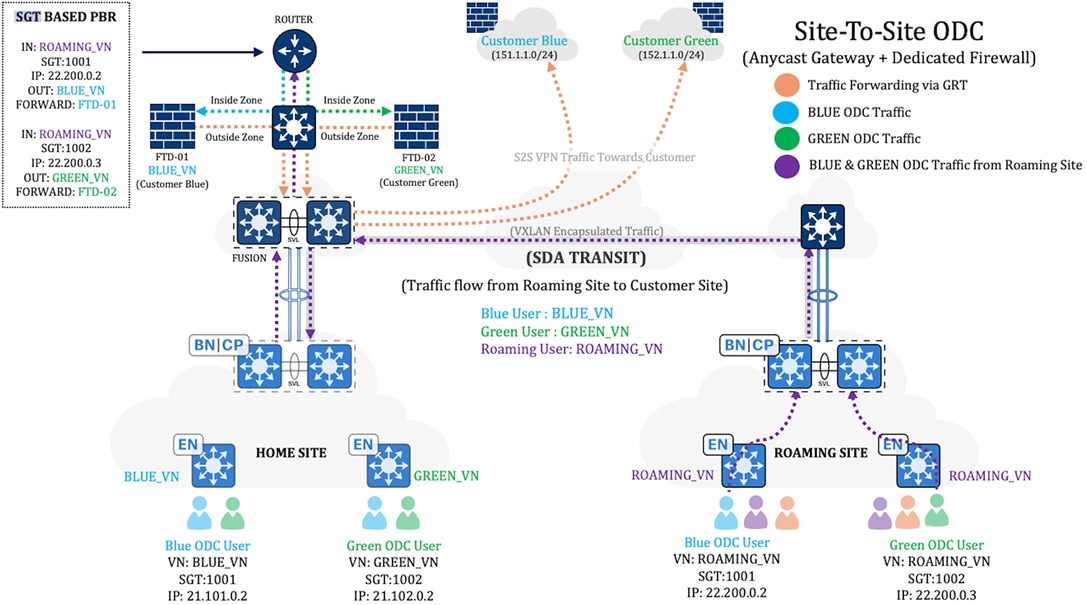
Note: Refer to the legend and arrows, which indicate the flow of traffic.
Location agnostic access for site-to-site ODC with dedicated firewall and anycast gateway
Business requirements:
● Return To Office (RTO) Requirements for ITES Customers:
◦ ODC client location is abstracted, enabling work from any ITES site.
◦ Client traffic must be classified and tunneled to the home location for exit.
● Existing site-to-site ODC users should be able to work from any ITES site.
● ODC users should only have access to systems within their respective ODC, regardless of their location.
● Utilize the existing dedicated firewall for the site-to-site ODC at the home location.
Technical requirements:
● Provision a Layer 3 VN for site-agnostic clients, which will be referred to as 'roaming VN' throughout the document.
● Deploy an anycast gateway under the roaming VN at all necessary remote sites, excluding the home site.
● Install a router to implement SGT-based Policy-Based Routing (PBR) for roaming VN traffic.
● Configure the ISE to ensure proper authentication and authorization for roaming users.
● Use Macro (VN) or Micro (SGT) segmentation for the isolation of ODC users and systems.
● Update the existing firewall policies and site-to-site VPN configuration to accommodate the newly added subnet for roaming users.
Tech tip: A roaming VN is typically a virtual network that facilitates seamless connectivity and mobility across different geographical locations. It enables users to maintain consistent network access and services as they move between sites. The roaming VN is crucial for ensuring that a user's experience remains uninterrupted and secure, regardless of their physical location within the ITES infrastructure.
Prerequisite:
● Multisite SD-Access using a LISP Pub/Sub transit.
● A router to do SGT-based PBR.
● Site-to-site ODC with a dedicated firewall at the home site.
Procedure 11.
Step 1. Provision a Layer 3 VN for location agnostic clients, known as roaming VN, and deploy it to all necessary remote sites connected via SD-Access Transit (in other words, LISP Pub/Sub), including the home site.
Step 2. Deploy an anycast gateway under the roaming VN at all necessary remote sites, excluding the home site. Then, do the Layer 3 handoff at the home site for traffic exit.
Step 3. Install a router at the home location to implement SGT based PBR. See to the topology in Figure 51 for the router placement.
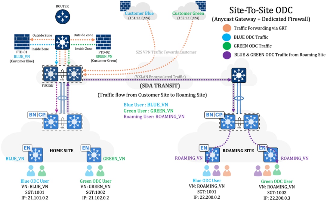
Step 4. To ensure proper authentication and authorization for roaming users when onboarding from the roaming site, configure the ISE according to these steps:
i. Create a location under the Network Device Group on the ISE for each roaming site.
ii. Update the location of existing Network Access Devices (NADs) and assign them to the respective location.
iii. Configure the authorization profiles and authorization policies for onboarding roaming users.
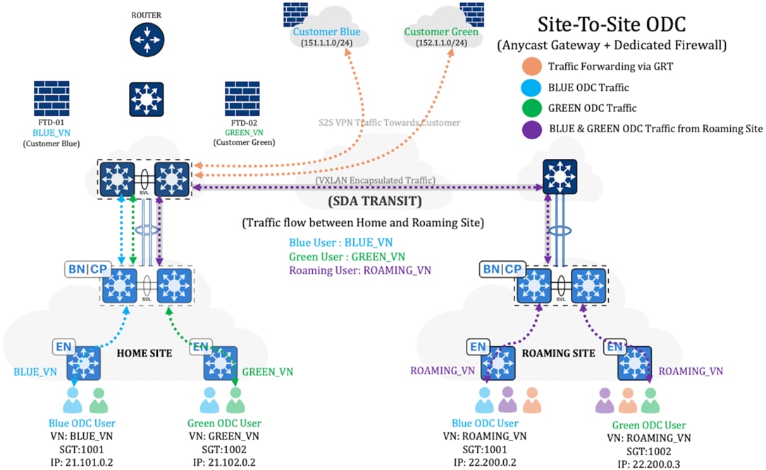
Tech tip: To ensure that the appropriate attributes are matched before authenticating end users, the policy for roaming users is positioned above the policy for home users.
Step 5. Update the existing Site-to-Site Firewall Policy to permit traffic from the roaming VN subnet. Additionally, include the roaming VN subnet as a protected network for the Site-to-Site VPN and update the NAT policies accordingly.
Step 6. Configure the routing for traffic destined for the customer site:
- Traffic from the site-to-site ODC user at the home site destined for the customer network should be forwarded to the dedicated firewall of that ODC.
- Traffic from the site-to-site ODC user at the roaming site (in other words, roaming VN traffic) destined for the customer network should be directed to the router, where SGT-based PBR ensures it is routed to the appropriate firewall.
Note: Confirm that the roaming client’s tag is preserved all the way to the steering router.

Note: Refer to the legend and arrows, which indicate the flow of traffic.
The summary of traffic flow from the roaming site to the customer site in the topology described in Figure 53 includes:
● Roaming client traffic (in other words, purple flow) from the roaming site is forwarded to the router through the home site’s border node and fusion.
● Router then does SGT-based PBR, forwarding ingress traffic with SGT 1001 to the inside zone of the customer blue firewall (in other words, FTD-01) and traffic with SGT 1002 to the inside zone of the customer green firewall (in other words, FTD-02).
Step 7. Configure the routing for traffic destined for the roaming site accordingly:
- Configure the Site-to-Site ODC firewall to forward return traffic, or traffic initiated from the customer site and intended for the roaming site, to the fusion node.
- Configure VRF route leaking on the fusion node to enable the Site-to-Site ODC VN to learn about the roaming subnets and vice versa.

Note: Refer to the legend and arrows, which indicate the flow of traffic.
The summary of traffic flow from the customer site to the roaming site in the topology described in Figure 54 includes:
● Traffic originating from the customer site and destined for blue ODC and green ODC clients at the roaming site is first received by the customer's dedicated firewall, which then forwards it to the fusion node.
● The fusion node passes this traffic to the roaming VN at the home site’s border node, which subsequently directs it to the roaming site.
Step 8. Communication between site-to-site ODC users onboarded from the home site and the roaming site should function properly as part of the route exchange, provided that the home site offers internet access to other sites through Cisco SD-Access. If this is not the case, you'll need to do these tasks:
- Make the roaming VN on the home site’s border node aware of the site-to-site ODC subnet.
- Import its routes into the LISP instance.

Note: Refer to the legend and arrows, which indicate the flow of traffic.
Step 9. If the allow-list (default deny IP) is enabled, choose one of the following options. Also, ensure that the correct policy matrix is configured for the source and destination security tags.
- Establish a VRF-aware SXP session between Cisco ISE and the VN's Layer 3 border node to obtain the destination addresses' security tags.
- Manually configure the subnet-to-SGT mapping.
Hardware and software specifications
The ITES vertical has been tested with the hardware and software specified in the table. For a comprehensive list of hardware supported by the Cisco SD-Access solution, refer to the Cisco Software Defined Access Compatibility Matrix.
| Hardware or software component |
Supported software version |
|
| Catalyst Center Appliance (Part Number: DN3-HW-APL-XL) |
2.3.7.9 |
2.3.7.10 |
| Identity Services Engine (ISE) |
3.3 Patch 4 |
3.4 Patch 3 |
| Control Plane Node |
17.12.4b, 17.15.2a |
17.12.4b, 17.15.2a |
| Fabric Border Node |
17.9.6a, 17.12.5, 17.15.3 |
17.12.6, 17.15.4d, 17.18.3 |
| Fabric Edge Node Cisco Catalyst 9200, 9300, and 9400 Series switches |
17.9.6a, 17.12.5, 17.15.3 |
17.12.6, 17.15.4d, 17.18.3 |
| Wireless Controller |
17.12.5, 17.9.6 |
17.12.6, 17.15.4d, 17.18.3 |
| Cisco Secure Firewall Management Center (FMC): |
7.4.2 |
7.4.2 |
| Cisco Secure Firewall Threat Defense (FTD) |
7.4.2 |
7.4.2 |
Multidimensional scale numbers
| Category |
Value |
| Devices in inventory (includes routers, switches, and wireless controllers) |
5000 |
| Number of fabric sites |
100 |
| Number of buildings and floors |
4000 |
| Number of IP pools per site |
1000 |
| Number of VNs per site |
128 |
| Number of wireless controllers per site |
2 with HA |
| Number of APs (fabric and nonfabric) |
8000 |
| Number of SGTs |
4000 |
| Number of group-based policies |
12,000 |
| Number of endpoints |
100,000 (30% wired and 70% wireless) |
| Route-map entries (match & set)—for SGT-based policy-based routing (PBR) |
125 |
Note: The officially supported scales are outlined in this data sheet, while the data provided here has been validated in the lab.
Network as Code (NaC) for efficient deployments:
The ITES network deployments embrace a Network as Code (NaC) approach, ensuring consistent, scalable, and repeatable configurations for ITES infrastructure. By leveraging Ansible Playbooks specifically developed for Cisco Catalyst Center-based deployments, we fully automate the entire deployment lifecycle. This includes everything from provisioning and initial configuration to final validation, which significantly reduces manual effort and the potential for human error. This enhances operational efficiency, accelerates change implementation, and aligns with modern DevOps principles for agile network management.
To learn more about our network automation practices, we encourage you to explore our automation repository. It features practical examples, reusable Ansible Playbooks tailored for ITES network deployments, and proven best practices designed to support scalable, efficient network operations. Visit the repository to gain deeper insights and begin your automation journey with confidence.
For more details, please refer to following repository.
https://github.com/DNACENSolutions/NetworkasCode_CVPs
https://github.com/DNACENSolutions/NetworkasCode_CVPs/tree/main/nac_ites_sda
Links to relevant Cisco documentation
● Cisco SD-Access Solution Design Guide (CVD)
● Catalyst Center User Role Permissions
● Release Notes for Cisco Catalyst Center
● Cisco Catalyst Center Security Best Practices Guide
● Software Defined Access (SD-Access) Provisioning Best Practice Guide