Enable ISE TrustSec Allow-List Model (Default Deny IP) With SDA
Available Languages
Download Options
Bias-Free Language
The documentation set for this product strives to use bias-free language. For the purposes of this documentation set, bias-free is defined as language that does not imply discrimination based on age, disability, gender, racial identity, ethnic identity, sexual orientation, socioeconomic status, and intersectionality. Exceptions may be present in the documentation due to language that is hardcoded in the user interfaces of the product software, language used based on RFP documentation, or language that is used by a referenced third-party product. Learn more about how Cisco is using Inclusive Language.
Contents
Introduction
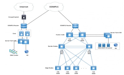
This document describes how to enable the allow-list (Default Deny IP) model of TrustSec in Software Defined Access (SDA). This document involves multiple technology and components which include Identity Services Engine (ISE), Digital Network Architecture Center (DNAC), and switches (Border and Edge).
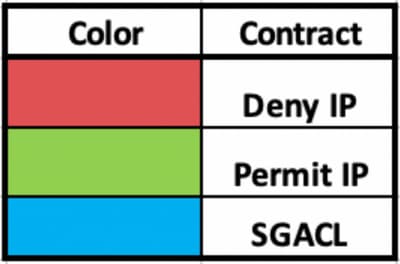
There are two TrustSec models available:
- Deny-List Model (Default Permit IP) - In this model, the default action is Permit IP and any restrictions must be explicitly configured with the use of Security Group Access Lists (SGACLs). This is generally used when you do not have a complete understanding of traffic flows within their network. This model is fairly easy to implement.
- Allow-List Model (Default Deny IP) - In this model, the default action is Deny IP and hence the required traffic must be explicitly permitted with the use of SGACLs. This is generally used when you have a fair understanding of the kind of traffic flows within their network. This model requires a detailed study of the control plane traffic as well as it has the potential to block ALL traffic, the moment it is enabled.
Prerequisites
Requirements
Cisco recommends that you have knowledge of these topics:
- Dot1x/MAC Authentication Bypass (MAB)
- Cisco TrustSec (CTS)
- Security exchange Protocol (SXP)
- Web proxy
- Firewall concepts
- DNAC
Components Used
The information in this document is based on these software and hardware versions:
- 9300 Edge and 9500 Border Nodes (switches) with Cisco IOS® Release 16.9.3
- DNAC 1.3.0.5
- ISE 2.6 patch 3 (Two Nodes - Redundant Deployment)
- DNAC and ISE are integrated
- Border and Edge nodes are provisioned by DNAC
- The SXP tunnel is established from ISE (Speaker) to both border nodes (Listener)
- IP address pools are added to host onboarding
The information in this document was created from the devices in a specific lab environment. All of the devices used in this document started with a cleared (default) configuration. If your network is live, ensure that you understand the potential impact of any command.
Configure
Network Diagram
Configuration
These are the steps to enable Allow-List Model (Default Deny IP):
- Change Switches Security Group Tag (SGT) from Unknown to TrustSec Devices.
- Disable CTS Role-based enforcement.
- IP-SGT Mapping on Border and Edge switches using DNAC Template.
- Fallback SGACL using DNAC Template.
- Enable Allow-List (Default Deny IP) in trustsec Matrix.
- Create SGT for Endpoint/Users.
- Create SGACL for Endpoint/Users (For Production Overlay Traffic).
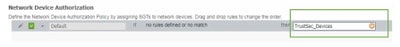
Step 1. Change Switches SGT from Unknown to TrustSec Devices.
By default, unknown SGT is configured for network device authorization. Changing it to TrustSec Device SGT gives more visibility and helps to create SGACL specific for Switch initiated traffic.
Navigate to Work Centres > TrustSec > Trustsec Policy > Network Device Authorization and then change it to Trustsec_Devices from Unknown.
Step 2. Disable CTS Role-Based Enforcement.
- Once Allow-List model (Default Deny) is in place, all the traffic is blocked in the fabric, which includes underlay multicast and broadcast traffic such as Intermediate System-to-Intermediate System (IS-IS), Bidirectional Forwarding Detection (BFD), and Secure Shell (SSH) traffic.
- All the TenGig ports that connect to the fabric edge as well the border must be configured with this command. With this in place, traffic initiated from this interface and that comes to this interface is not subject to enforcement.
Interface tengigabitethernet 1/0/1

no cts role-based enforcement
Note: This can be completed with the use of a range template in DNAC for simplicity. Otherwise, for every switch, it is required to be completed manually during provisioning. The next code snippet shows how to do it via a DNAC template.
interface range $uplink1

no cts role-based enforcement
For more information on DNAC templates, refer to this URL for the document.
Step 3. IP-SGT Mapping on Border and Edge Switches with DNAC Template.
The idea is for Local IP-SGT mapping is to be available on the switches even if all ISEs go down. This ensures Underlay is up and connectivity to the critical resources are intact.
The first step is to bind critical services to an SGT. For example, Basic_Network_Services/1000. Some of these services include:
- Underlay/ISIS Subnet
- ISE/DNAC
- Monitoring Tool
- AP's Subnet in case of OTT
- Terminal Server
- Critical Services - for example, IP Phone
An example is shown here:
cts role-based sgt-map <ISE/DNAC Subnet> sgt 1000

cts role-based sgt-map  sgt 2

cts role-based sgt-map <Wireless OTT Infra> sgt 1000

cts role-based sgt-map <Underlay OTT AP Subnet> sgt 2

cts role-based sgt-map <Monitoring Tool IP> sgt 1000

cts role-based sgt-map vrf CORP_VN <Voice Gateway and CUCM Subnet> sgt 1000
Step 4. Fallback SGACL with DNAC Template.
An SGT mapping is of no use until a relevant SGACL is created using the SGT, and hence our next step would be to create an SGACL that acts as a local Fallback in case ISE nodes go down (when ISE services are down, SXP tunnel goes down and hence SGACLs and IP SGT mapping is not downloaded dynamically).
This configuration is pushed to all Edge and border nodes.
Fallback Role-based ACL/Contract:>
ip access-list role-based FALLBACK

permit ip
TrustSec Devices to TrustSec Devices:
cts role-based permissions from 2 to 2 FALLBACK
Above SGACL Ensure communication within Fabric switches and underlay IP’s
TrustSec Devices to SGT 1000:
cts role-based permissions from 2 to 1000 FALLBACK
Above SGACL Ensure communication from switches and Access points to ISE, DNAC, WLC and Monitoring Tools
SGT 1000 to TrustSec Devices:
cts role-based permissions from 1000 to 2 FALLBACK
Above SGACL Ensure communication from Access points to ISE, DNAC, WLC and Monitoring Tools to switches
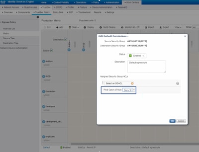
Step 5. Enable Allow-List Model (Default Deny) in TrustSec Matrix.
The requirement is to deny most traffic on the network and permit a lesser extent. Then fewer policies are needed if you use default deny with explicit permit rules.
Navigate to Work Centres > Trustsec > TrustSec Policy > Matrix > Default and change it to Deny All in final catch rule.
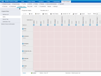
Note: This image represents (All Columns are in Red by default), Default Deny has been enabled and only selective traffic can be allowed after SGACL creation.
Step 6. Create SGT for Endpoint/Users.
In SDA Environment, New SGT must only be created from DNAC GUI as there are numerous cases of database corruption due to the mismatch of the SGT database in ISE/DNAC.
In order to Create SGT, log in to DNAC > Policy > Group-Based Access Control > Scalable Groups > Add Groups, a Page Redirects you to ISE Scalable Group, click Add, enter the SGT name and Save it.
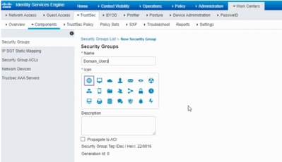
The same SGT reflects in DNAC through PxGrid integration. This is the same procedure for all future SGT creation.
Step 7. Create SGACL for Endpoints/Users (For Production Overlay Traffic).
In SDA Environment, New SGT can only be created from the DNAC GUI.
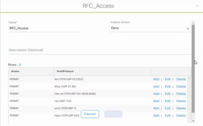
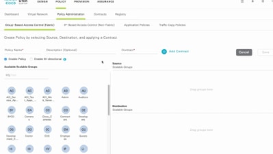
Policy Name: Domain_Users_Access

Contract : Permit

Enable Policy :√

Enable Bi-Directional :√

Source SGT : Domain Users (Drag from Available Security Group)

Destination SGT: Domain_Users, Basic_Network_Services, DC_Subnet, Unknown (Drag from Available Security Group)


Policy Name: RFC_Access

Contract : RFC_Access (This Contract contains limited ports)

Enable Policy :√

Enable Bi-Directional :√

Source SGT : Domain Users (Drag from Available Security Group)

Destination SGT: RFC1918 (Drag from Available Security Group)
In order to create a Contract, log in to DNAC and navigate to Policy > Contracts > Add Contracts > Add required protocol and then click Save.
In order to create a Contract, log in to DNAC and navigate to Policy > Group-Based Access Control > Group-Based-Access-Policies > Add Policies > Create policy (with the given information) now click Save and then Deploy.
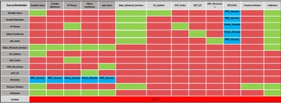
Once SGACL/Contract is configured from DNAC, it automatically reflects in ISE. here is an exapmle of one way matrx view for a sgt.

SGACL Matrix, as shown in this image, is an example view for Allow-list (Default Deny) model.
Verify
Use this section to confirm that your configuration works properly.
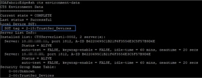
Network Device SGT
In order to verify the switches SGT received by ISE, run this command: show cts environmental-data
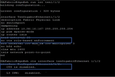
Enforcement on Uplink Ports
In order to verify enforcement on the uplink interface, enter these commands:
- show run interface <uplink>
- show cts interface <uplink interface>
Local IP-SGT Mapping
In order to verify locally configured IP-SGT mappings, enter this command: sh cts role-based sgt-map all

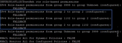
Local FALLBACK SGACL
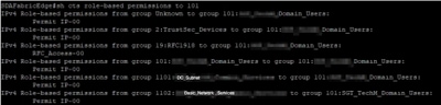
In order to verify FALLBACK SGACL, run this command: sh cts role-based permission
Note: SGACL pushed by ISE has a priority over local SGACL.
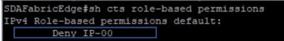
Allow-List (Default Deny) Enablement on Fabric Switches
In order to verify Allow-list (Default Deny) model, enter this command: sh cts role-based permission
SGACL for Endpoint Connected to Fabric
In order to verify downloaded SGACL from ISE, run this command: sh cts role-based permission
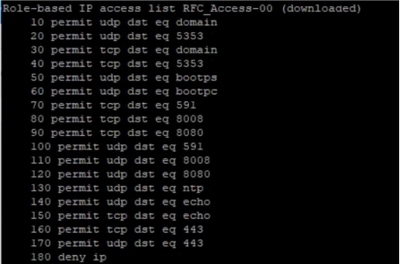
Verify Contract created by DNAC
In order to verify downloaded SGACL from ISE, run this command: show access-list <ACL/Contract Name>

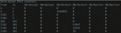
Underlay SGACL Counter on Fabric Switches
In order to verify SGACL policy hits, run this command: Show cts role-based counter
Troubleshoot
This section provides information you can use to troubleshoot your configuration.
Issue 1. In Case Both the ISE Nodes are Down. ( Only if Border node are used as north-south enforcement point)
In case both the ISE nodes are down, IP-to-SGT mapping received by ISE is removed on border nodes and all the DGT's are tagged as unknown, and all the user sessions that exist stops after 5-6 minutes.
Note: This issue is applicable only when sgt (xxxx) -> unknown (0) SGACL access is limited to DHCP, DNS, and web proxy port.
Solution:
- Created an SGT (ex. RFC1918).
- Push RFC private IP range to both the border.
- Limit the access to DHCP, DNS and web proxy from sgt (xxxx) --> RFC1918
- Create/modify sgacl sgt (xxxx) --> unknown with Permit IP contract.
Now if both the ise nodes go down, SGACL sgt-->unknown hits, and the session that exists are intact.
Issue 2. IP-Phone One-Way Voice or No Voice.
Extension to IP conversion happened on SIP and actual voice communication happen over RTP between IP to IP. CUCM and Voice Gateway were added to DGT_Voice.
Solution:
- Same location or east-west voice communication can be enabled by allowing traffic from IP_Phone --> IP_Phone.
- The rest of the location can be allowed by the Permitting RTP protocol range in DGT RFC1918. The same range can be allowed for IP_Phone --> Unknown.
Issue 3. Critical VLAN Endpoint has No Network Access.
DNAC provisions switch with critical VLAN for Data and as per the configuration, all new connections during ISE outage get Critical VLAN and SGT 3999. The Default Deny in trustsec policy restricts the new connection to access any network resources.
Solution:
Push SGACL for Critical SGT on All Edge and Border switches using DNAC Template
cts role-based permissions from 0 to 3999 FALLBACK

cts role-based permissions from 3999 to 0 FALLBACK
These commands are added to the configuration section.
Note: All the commands can be combined into a single template and can be pushed during provisioning.
Issue 4. Packet Drop-in Critical VLAN.
Once the machine is in critical VLAN due to ISE nodes down, there is a packet drop in every 3-4 minutes (Max 10 drops observed) for all the endpoints in critical VLAN.
Observations: Authentication counters increasing when servers are DEAD. Clients try to authenticate with PSN when servers were marked DEAD.
Solution/Workaround:
Ideally, there cannot be any auth request from an endpoint if ISE PSN nodes are down.
Push this command in under radius server with DNAC:
automate-tester username auto-test probe-on
With this command in the switch, it sends periodic test authentication messages to the RADIUS server. It looks for a RADIUS response from the server. A success message is not necessary - a failed authentication suffices because it shows that the server is alive.
Additional Information
DNAC Final Template:
interface range $uplink1

no cts role-based enforcement

! .

cts role-based sgt-map <ISE Primary IP> sgt 1102

cts role-based sgt-map <Underlay Subnet> sgt 2

cts role-based sgt-map <Wireless OTT Subnet>sgt 1102

cts role-based sgt-map <DNAC IP> sgt 1102

cts role-based sgt-map <SXP Subnet> sgt 2

cts role-based sgt-map <Network Monitoring Tool IP> sgt 1102

cts role-based sgt-map vrf CORP_VN <Voice Gateway Subnet> sgt 1102

!

ip access-list role-based FALLBACK

permit ip

!

cts role-based permissions from 2 to 1102 FALLBACK

cts role-based permissions from 1102 to 2 FALLBACK

cts role-based permissions from 2 to 2 FALLBACK

cts role-based permissions from 0 to 3999 FALLBACK

cts role-based permissions from 3999 to 0 FALLBACK
Note: All uplink interfaces in edge nodes are configured without enforcement and assumption is that uplink connects to border node only. On Border nodes, uplink interfaces towards edge nodes need to configure without enforcement and that has to be done manually.
Revision History
| Revision | Publish Date | Comments |
|---|---|---|
1.0 |
08-May-2020
|
Initial Release |
Contributed by
- Nitesh KalalCisco Advance Services
 Feedback
Contact Cisco
- Open a Support Case

- (Requires a Cisco Service Contract)