
Cisco Catalyst Center Security Best Practices Guide
Security hardening overview
Deploy Catalyst Center securely. Catalyst Center is a critical part of your enterprise network.
This article explains the best practices for ensuring a secure deployment. Review security considerations for Catalyst Center in your network infrastructure, and take the recommended actions to reduce security risks.
 Note
Note- This content is updated regularly whenever there are new security enhancements in Catalyst Center.
- This content is release-agnostic. Screenshots and procedures reflect the latest UI. If you use an earlier version of Catalyst Center and notice differences in screenshots or workflows, refer to the Cisco Catalyst Center Administrator Guide for that version.
Catalyst Center hardening steps
Catalyst Center provides many security features for itself, for the hosts and network devices that it monitors and manages. Understand the security features clearly and configure them correctly. Follow these security recommendations:
- Deploy Catalyst Center in a private internal network and behind a firewall that does not expose Catalyst Center to an untrusted network, such as the internet.
- Connect interfaces of Catalyst Center to your separate management and enterprise networks. This ensures isolation between services used to administer Catalyst Center and those used to communicate with network devices
- If deploying Catalyst Center in a three-node cluster setup, verify that the cluster interfaces are connected in an isolated network.
- Upgrade Catalyst Center promptly with critical upgrades, including security patches, after a patch announcement. Refer to the Cisco Catalyst Center Upgrade Guide.
- Restrict the remote URLs accessed by Catalyst Center using an HTTPS proxy server. Catalyst Center is configured to access the internet to download software updates, licenses, and device software, as well as provide up-to-date map information and user feedback. Internet connections for these purposes are mandatory. However, provide connections securely through an HTTPS proxy server. For more information, refer to Secure internet access to required internet URLs and fully qualified domain names.
- Restrict the ingress and egress management and enterprise network connections to and from Catalyst Center using a firewall. Restrict access by allowing known IPs and blocking connections to unused ports.
- Replace the self-signed server certificate from Catalyst Center with one signed by your internal certificate authority (CA)
- If possible, disable SFTP Compatibility Mode in your network environment. This mode allows legacy network devices to connect to Catalyst Center using older cipher suites. For more information, refer to Enable or disable SFTP compatibility mode.
- Disable the browser-based appliance configuration wizard, which comes with a self-signed certificate. For more information, refer to Browser-based appliance configuration wizard.
- Upgrade the minimum TLS version. Catalyst Center comes with TLSv1.1 and TLSv1.2 enabled by default. We recommend that you set the minimum TLS version to 1.2 in your network environment. For more information, refer to Change the minimum TLS version and enable RC4-SHA (not secure).
User role considerations
Users are assigned roles that define their access to specific functions.
Catalyst Center supports these user roles:
- Administrator (SUPER-ADMIN-ROLE): Users with this role have full access to all Catalyst Center functions. They can create other user profiles with various roles, including roles like the SUPER-ADMIN-ROLE. Restrict the number of users with this role.
- Network Administrator (NETWORK-ADMIN-ROLE): Users with this role have full access to all the network-related Catalyst Center functions. However, they do not have access to system-related functions, such as backup and restore.
- Observer (OBSERVER-ROLE): Users with this role have view-only access to Catalyst Center functions. Users with the observer role cannot access functions to configure or control Catalyst Center or manage the devices
In addition to the preconfigured user roles, Catalyst Center also supports the creation of user roles with a custom fine-grained access policy. Such user roles allow the creation of custom roles to permit or restrict user access to certain Catalyst Center functions and sites. For more information, refer to "Configure site-based, role-based access control" in the Cisco Catalyst Center Administrator Guide.
NoteCatalyst Center can use Cisco Identity Services Engine (ISE) or other authentication, authorization, and accounting (AAA) servers for user authentication. For more information, refer to "Configure authentication and policy servers" in the Cisco Catalyst Center Administrator Guide.
Secure your Catalyst Center deployment
Catalyst Center provides many security features for itself and for the hosts and network devices that it monitors and manages. Place Catalyst Center and Cisco ISE behind a firewall in a local data center (head of campus) or a remote data center as shown in the figure.
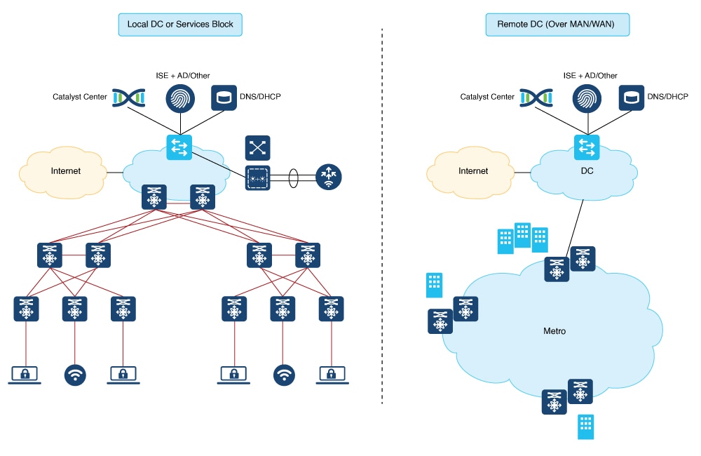
Configure specific ports on the firewall for GUI access to Catalyst Center and enable interaction with network devices. Catalyst Center integrates with the cloud to meet latency requirements and is distributed globally.
Communication ports
For a description of the ports that Catalyst Center uses for communication, refer to these topics in the “Plan the Deployment” chapter of the Cisco Catalyst Center Installation Guide:
- Communication ports
- HTTP port 80 exception list
- Disaster recovery ports
Enable Catalyst Center disaster recovery
Catalyst Center provides a mechanism to recover from a Catalyst Center cluster loss (or a data center loss) and maintain operational continuity. The Disaster Recovery application facilitates recovery by replicating essential data from the main Catalyst Center cluster to a secondary, standby cluster.
Security recommendation: We recommend that you enable Catalyst Center's Disaster Recovery Service to recover from a Catalyst Center cluster loss (or a data center loss) and maintain operational continuity.
The Catalyst Center recovery cluster contains all the essential data such as Mongodb, Postgresql, credentials and certificates, and file service replicated from the main Catalyst Center cluster. It takes control in case the main Catalyst Center cluster is lost. For more information, refer to "Set up disaster recovery" in the Cisco Catalyst Center Administrator Guide.
NoteDisaster recovery uses IPsec tunneling to secure network traffic between the main, recovery, and witness systems. Authentication to set up the IPsec tunneling between disaster recovery systems is done through certificate-based methods using OpenSSL certificates.
For the key-exchange phase of the IPsec protocol, IPsec tunneling uses the secure and robust IKE2 protocol.
Use a separate certificate (as from the Catalyst Center system certificate for HTTPS connections) for disaster recovery. For more information, refer to "Add the disaster recovery certificate" in the Cisco Catalyst Center Administrator Guide.
Check the disaster recovery certificate requirement
If you plan to use disaster recovery, import the certificate that the disaster recovery system will use for intracluster communications. For a description of how to do so, refer to "Add the disaster recovery certificate" in the Cisco Catalyst Center Administrator Guide.
Note- Ensure that all IP addresses, such as the Enterprise port virtual IP address, and fully qualified domain names (FQDN), used by both the main and recovery sites, are included in this certificate. Also ensure that digitalSignature is specified for the certificate keyUsage parameter.
- For a description of how to generate a third-party certificate, refer to Generate a certificate request using OpenSSL.
Select one of these tasks based on whether you are using an FQDN-only certificate for Disaster Recovery:
-
If you are using an FQDN-only certificate: Use the same cluster_hostname—that is, the FQDN for Catalyst Center (set in the Catalyst Center configuration wizard)—in both the main and recovery clusters, as well as Disaster Recovery's VIP. Certificate subject alternative names (alt_names sections) look similar to this example:
[alt_names] DNS.1 = FQDN-of-Catalyst-Center -
If you are not using an FQDN-only certificate: Use different cluster_hostnames—that is, the FQDNs for Catalyst Center in an enterprise network (set in the Catalyst Center configuration wizard)—in both the main and recovery clusters. Certificate subject alternative names (alt_names sections) look similar to this example:
[alt_names]
DNS.1 = FQDN-of-Catalyst-Center-Main
DNS.2 = FQDN-of-Catalyst-Center-Recovery
NoteIf you plan to use PnP, refer to Check the PnP certificate requirement.
Secure internet access to required internet URLs and fully qualified domain names
Security recommendation: We recommend that you allow secure access only to URLs and Fully Qualified Domain Names that are required by Catalyst Center, through an HTTPS proxy.
For more information, refer to "Required internet URLs and fully qualified domain names" and "Provide secure access to the internet" in the latest Cisco Catalyst Center Appliance Installation Guide.
Secure the management interface
If you are using Cisco Integrated Management Controller (IMC), secure the out-of-band management interface (Cisco IMC) account on the Catalyst Center appliance. Change the default password of the admin account to a stronger value as per the password policy. Refer to "Enable browser access to Cisco IMC" in the Cisco Catalyst Center Appliance Installation Guide and "Configure external authentication" in the Cisco Catalyst Center Administrator Guide.
NoteYou must secure the password of Maglev CLI users with super admin access. For details, refer to "Configure the primary node" in the Cisco Catalyst Center Administrator Guide.
Rate limit IP traffic to an interface
Security recommendation: We recommend that you rate limit the incoming IP traffic to Catalyst Center from your network devices.
By default, Catalyst Center does not rate limit IP traffic to its interfaces. However, we recommend that you rate limit the incoming IP traffic from either a specific source IP or all the traffic to a Catalyst Center interface. This limiting helps in protecting against DoS/DDoS attacks from internal network threats.
Before you begin
You must have root shell access privileges to do this procedure. To obtain root shell access, contact the Cisco TAC. For more information, refer to "About restricted shell" in the Cisco Catalyst Center Administrator Guide.
Step 1 | Using an SSH client, log in to the Catalyst Center appliance with the IP address that you specified using the configuration wizard. The IP address that you must enter for the SSH client is the one you configured for the network adapter. This IP address connects the appliance to the external network. |
Step 2 | When prompted, enter your username and password for SSH access. |
Step 3 | Enter this command to restrict the incoming traffic from a specific source: If you don’t enter a specific IP address, the full interface becomes throttled. The mandatory interface name limits the input transmission rate for all classes of traffic that are based on user-defined criteria. |
Step 4 | Log out of the Catalyst Center appliance. |
Change the minimum TLS version and enable RC4-SHA (not secure)
Security recommendation: Upgrade the minimum TLS version to TLSv1.2 for incoming TLS connections to Catalyst Center.
Northbound REST API requests from an external network, include northbound REST API-based apps, browsers, and network devices connecting to Catalyst Center using HTTPS. The Transport Layer Security (TLS) protocol makes such requests secure.
By default, Catalyst Center supports TLSv1.1 and TLSv1.2, but does not support RC4 ciphers for SSL/TLS connections. Since RC4 ciphers have well-known weaknesses, we recommend that you upgrade the minimum TLS version to TLSv1.2 if your network devices support it.
Catalyst Center provides a configuration option to downgrade the minimum TLS version and enable RC4-SHA. You can use this option if your network devices under Catalyst Center control cannot support the existing minimum TLS version (TLSv1.1) or ciphers. For security reasons, however, we recommend that you do not downgrade Catalyst Center TLS version or enable RC4-SHA ciphers.
To change the TLS version or enable RC4-SHA for Catalyst Center, log in to the corresponding appliance and use the CLI.
NoteBefore you begin
You must have maglev SSH access privileges to do this procedure.
NoteStep 1 | Using an SSH client, log in to the Catalyst Center appliance with the IP address that you specified using the configuration wizard. The IP address to enter for the SSH client is the IP address that you configured for the network adapter. This IP address connects the appliance to the external network. |
Step 2 | When prompted, enter your username and password for SSH access. |
Step 3 | Enter this command to check the TLS version currently enabled on the cluster. Here is an example: |
Step 4 | If you want to change the TLS version on the cluster, enter these commands. For example, you can change the current TLS version to an earlier version if your network devices under Catalyst Center control cannot support the existing TLS version. This example shows how to change from TLS Version 1.1 to 1.0: This example shows how to change from TLS Version 1.1 to 1.2 (only allowed if you haven't enabled RC4-SHA): TLS Version 1.2 cannot be set as the minimum version if RC4-SHA ciphers are enabled. |
Step 5 | If you want to change the TLS version for streaming telemetry connections between Catalyst Center and Catalyst 9000 devices (via the TCP 25103 port), enter this command. For example, you can change the current TLS version if the network devices that Catalyst Center manages can support TLS version 1.2. This example shows how to change from TLS Version 1.1 to 1.2: |
Step 6 | Enter this command to enable RC4-SHA on a cluster (not secure; proceed only if needed). Enabling RC4-SHA ciphers is not supported when TLS Version 1.2 is the minimum version. This example shows TLS version 1.2 is not enabled:
|
Step 7 | Enter the command at the prompt to confirm that TLS and RC4-SHA are configured. Here is an example: If RC4 and TLS minimum versions are set, they are listed in the env: of the magctl service display kong command. If these values are not set, they do not appear in the env:. |
Step 8 | To disable the RC4-SHA ciphers that you enabled previously, enter this command on the cluster: |
Step 9 | Log out of the Catalyst Center appliance. |
Use of OCSP and CRL for HTTPS connections by Catalyst Center
Catalyst Center uses Online Certificate Status Protocol (OCSP) and Certificate Revocation List (CRL) to confirm that a remote certificate is not revoked.
Step 1 | Catalyst Center checks for OCSP. If a valid OCSP URI or URL is present in the Authority Information Access (AIA) field of the certificate, Catalyst Center sends an OCSP request to the URI or URL to validate its revocation status.
|
Step 2 | Catalyst Center checks for CRL. If the certificate includes the CRL Distribute Points field, and that field has at least one entry with a valid CRL URI or URL, Catalyst Center downloads the CRL from the URI or URL, and validates the certificate against the downloaded CRL.
NoteCatalyst Center supports HTTP-type CRL. In the certificate, define OCSP, or in the CRL Distribution Points field, list HTTP CRL before Lightweight Directory Access Protocol (LDAP) CRL. Unless OCSP or HTTP CRL is available, Catalyst Center won't do the revocation check as it does not support LDAP/AD. To understand the sequence of how the CRL Distribution Points are checked, refer to CRL Distribution Points in the Internet X.509 Public Key Infrastructure Certificate and Certificate Revocation List (CRL) Profile. |
Manage credentials and passwords
Cluster password
Catalyst Center supports cluster formation with three nodes. For efficiency and security, we recommend these actions:
- You must create the cluster with dedicated interfaces for connecting to the enterprise network, forming an intracluster network, and connecting to a dedicated management network.
- The intracluster network is an isolated Layer 2 segment and not connected or routed through any other network segments.
- Use unique passwords for Cisco IMC or SSH across the Catalyst Center cluster members.
SSH or maglev password recovery
You must secure the SSH password. Share the SSH password only with the super admin. Catalyst Center does not provide the functionality to recover the SSH password.
SSH account lockout and recovery
After six consecutive failed login attempts over SSH, the maglev account is locked for five minutes. Login attempts with the correct password will fail and be counted as a failed login during this period. The account is unlocked for SSH login after five minutes of no activity. The console login for Cisco IMC remains active. The administrator can enable SSH login during the lockout period, by executing this command in the Linux shell:
sudo pam_tally2 --resetWeb UI password recovery
If a web UI user's password is lost, the password can be reset using the command-line shell, which requires SSH or console access. Refer to "Reset a forgotten password" in the Cisco Catalyst Center Administrator Guide.
Password encryption
By default, Catalyst Center's pluggable authentication module (PAM) uses the SHA-512 hashing algorithm to store and hash local user account passwords (the strongest method available for UNIX-based systems). No user-configurable action is available for Catalyst Center's password encryption mechanism.
Logs and database management
System logs are available to the operating system administrator user with escalated privileges (sudo access). The application logs are stored in Elasticsearch, and can be accessed through the web UI after authentication. The databases are protected by credentials, which are randomly generated during installation, and securely passed to the applications that need database access. No user-configurable action is available to change these settings.
Communication protocol payload encryption
In clustered mode, Catalyst Center nodes communicate with each other through the intracluster network. No separate encryption is applied to the intracluster traffic. It is important to keep the intracluster network isolated.
NoteServices that exchange sensitive data among themselves use HTTPS.
Change the GUI user and Linux user password
Security recommendation: Regularly change your Catalyst Center GUI user passwords and the Linux user's (maglev) password.
Step 1 | To change the Linux user's password:
|
Step 2 | To change the GUI user password:: NoteOnly you can change the password that you enter to log in to Catalyst Center. Even users with administrator privileges cannot change your password. If an administrator has to change a user's password, they must delete and re-add the user, using a new password.
|
Manage certificates
Default certificates
Security recommendation: We recommend that you replace the default Catalyst Center Transport Layer Security certificate with a certificate that is signed by your internal certificate authority.
By default, Catalyst Center uses self-signed certificates. Catalyst Center manages the devices using the devices' self-signed certificates, unless otherwise deployed. We strongly recommend that you use a certificate that is signed by your internal certificate authority during deployment.
Note- Changing the Catalyst Center certificate from either self-signed to certificate-signed by your internal CA or from root CA to subordinate CA reprovisions Catalyst Center-managed devices with the new trustpoint CA. The reprovisioning is initiated automatically; in Catalyst Center 2.3.7 and later, the network admin might need to approve the change. Until the device reprovision is complete, the device can’t authenticate a new TLS/HTTPS connection to Catalyst Center, which means the device cannot do SWIM operations, send Assurance telemetry, obtain configurations over PnP, and so on. As a result, we strongly recommend that you upgrade certificates before you begin the deployment.
- In the case of an FQDN-only certificate deployment, the device will be provisioned by Catalyst Center to use the cluster hostname (FQDN) to reach Catalyst Center, hence the DNS architecture must ensure that the FQDN can be resolved by the devices to the interface VIP or IP of the cluster.
Certificate and private key support
Catalyst Center supports the Certificate Authority Management feature, which is used to authenticate sessions (HTTPS). These sessions use commonly recognized trusted agents that are called CAs. Catalyst Center uses the Certificate Authority Management feature to import, store, and manage X.509 certificates from your internal CA. The imported certificate becomes an identity certificate for Catalyst Center, and Catalyst Center presents this certificate to its clients for authentication. The clients are the northbound API applications and network devices.
You can import these files (in either the PEM or PKCS file format) using the Catalyst Center GUI:
- X.509 certificate
- Private key
NoteFor the private key, Catalyst Center supports the import of RSA keys. Keep the private key secure in your own key management system. The private key must have a minimum modulus size of 2048 bits.
You must obtain a valid X.509 certificate and private key issued by your internal CA. The certificate must correspond to a private key in your possession before importing the files. After importing the files, the security functionality that is based on the X.509 certificate and private key is automatically activated. Catalyst Center presents the certificate to any device or application that requests it. Northbound API applications and network devices can use these credentials to establish a trust relationship with Catalyst Center.
NoteAvoid using and importing a self-signed certificate to Catalyst Center. Import a valid X.509 certificate from your internal CA. Replace the default self-signed certificate with one signed by your internal CA to ensure proper Plug and Play functionality
Catalyst Center supports only one imported X.509 certificate and private key at a time. When you import a second certificate and private key, the latter overwrites the first (existing) imported certificate and private key values.
Certificate chain support
Catalyst Center can import certificates and private keys through its GUI. Sometimes subordinate certificates are involved in a certificate chain, leading to the signed certificate that is to be imported into Catalyst Center. In such a case, append both the subordinate certificates and the root certificate of these subordinate CAs into a single file to be imported. Append these certificates in the same order as the actual chain of certification.
These certificates must be pasted together into a single PEM file. Review the certificate subject name and issuer to ensure that the correct certificates are imported and the correct order is maintained. Ensure that all the certificates in the chain are pasted together.
-
Signed Catalyst Center certificate: Its Subject field includes common name=<FQDN of Catalyst Center>, and the issuer has the common name (CN) of the issuing authority.
Note
If you install a third-party certificate, ensure that the certificate specifies all the DNS names (including the Catalyst Center FQDN) that are used to access Catalyst Center in the alt_names section. For more information, refer to Generate a certificate request using OpenSSL.
- Issuing (subordinate) CA certificate that issues the Catalyst Center certificate: Its Subject field has CN of the (subordinate) CA that issues the Catalyst Center certificate, and the issuer is that of the root CA.
- Next issuing (root/subordinate CA) certificate that issues the subordinate CA certificate: Its Subject field is the root CA, and the issuer has the same value as the Subject field. If they are not the same, you must append the next issuer, and so on.
Update the Catalyst Center server certificate
Catalyst Center allows you to import and store an X.509 certificate from your certificate authority (CA) and private key that's generated by Catalyst Center. These can be used to create a secure and trusted environment between Catalyst Center, northbound API applications, and network devices. You can import a certificate and a private key on the System Certificates window.
To update the Catalyst Center server certificate:
- Generate a Certificate Signing Request (CSR).
- Submit the CSR to your CA to get a signed certificate.
- Import the signed certificate and its chain into Catalyst Center.
This procedure uses Microsoft Active Directory Certificate Services as an example CA. If you use a different CA, adapt the steps accordingly.
Before you begin
You must obtain a valid X.509 certificate from your internal CA that corresponds to your private key.
Step 1 | From the main menu, choose . This window displays information about Catalyst Center server certificates and provides actions to manage those certificates. The System Certificates table displays this information for each certificate:
| |||||||||||||||
Step 2 | Click + New Certificate Request (CSR). This + New Certificate Request (CSR) link is enabled when you generate the CSR for the first time. If you don't want to use the existing CSR, delete the existing request.
NoteIf you are using an older version of Catalyst Center, click Replace Certificate. The Generate New CSR link displays when you are generating the CSR for the first time. Otherwise, the Download existing CSR link displays. For more information, refer to the Cisco Catalyst Center Administrator Guide. | |||||||||||||||
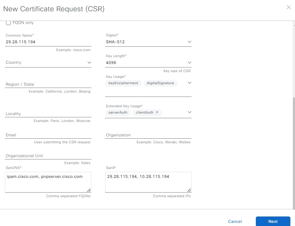
Step 3 | In the New Certificate Request (CSR) slide-in pane, create the CSR.
| |||||||||||||||
Step 4 | In the Certificate Signing Request slide-in pane, download a copy of the CSR.
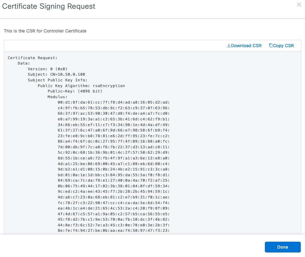 | |||||||||||||||
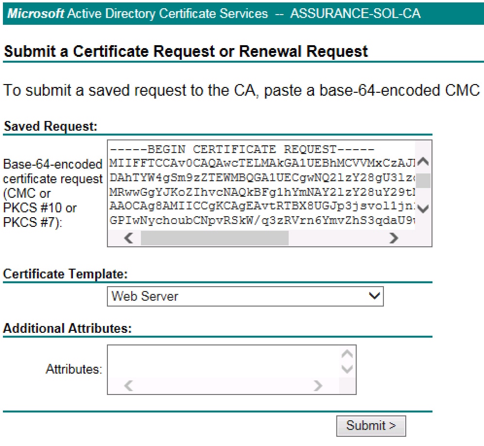
Step 5 | Submit a certificate request to the CA and download the issuer CA chain from the CA. For example, you can submit a certificate request using Microsoft Active Directory Certificate Services by following these steps.
| |||||||||||||||
Step 6 | Confirm that the certificate issuer provided the certificate full chain (server and CA) in p7b. When in doubt, complete these steps to examine and assemble the chain:
| |||||||||||||||
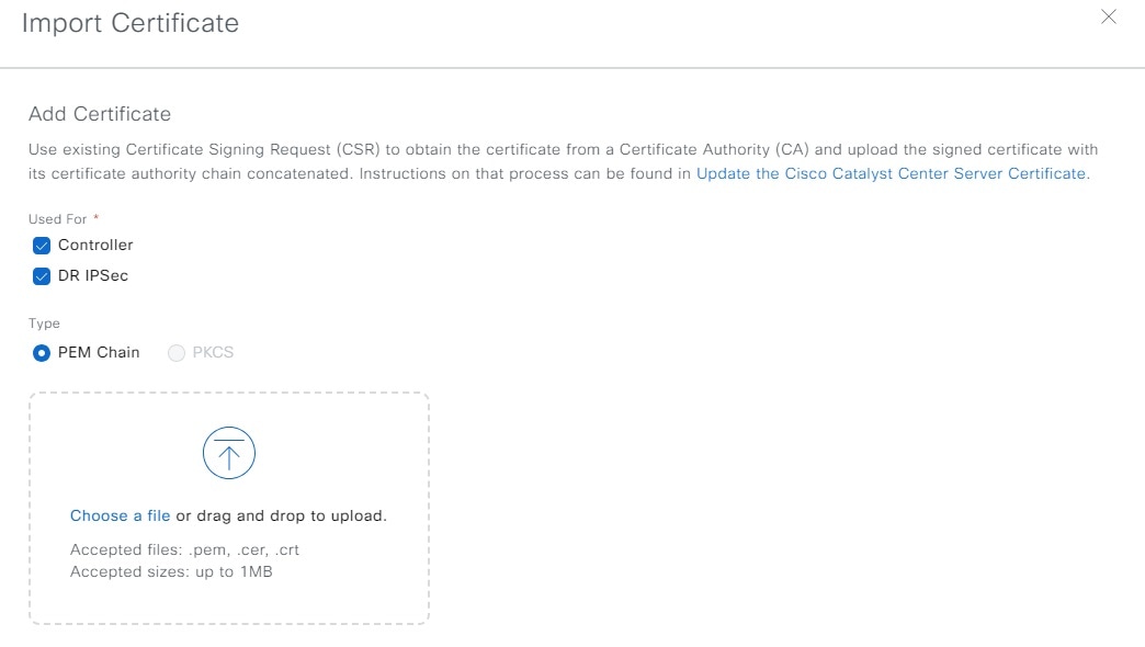
Step 7 | On the Catalyst Center GUI, in the + System Certificates window, click + Import Certificate. | |||||||||||||||
Step 8 | In the Import Certificate slide-in pane, import the signed certificate with its certificate signed authority chain concatenated into Catalyst Center.
| |||||||||||||||
Step 9 | After logging back in to Catalyst Center, go to the System Certificates window to view the updated certificate data. Under User For, click the hyperlinked text for the updated certificate to view a slide-in pane with information about the issuer, CA, and valid dates. |
Generate a certificate request using OpenSSL
OpenSSL is often used to create certificate signing requests (CSR) and private keys. There's an OpenSSL version for most platforms, including Windows, Linux, and Mac. Using OpenSSL, you will generate a certificate on your computer and then upload it to Catalyst Center. Before you complete this procedure, install the OpenSSL version that is specific to your platform.
Note- Whenever you need to update Catalyst Center's server certificate and private key, we recommend that you complete the steps described in Update the Catalyst Center server certificate. If you prefer a CLI-based procedure, complete the steps described in this topic.
- Refer to this URL for a description of the most commonly used OpenSSL commands: https://www.sslshopper.com/article-most-common-openssl-commands.html.
Step 1 | Ensure that the Catalyst Center hostname (FQDN) is set during Catalyst Center configuration by entering the maglev cluster network display command (requires root privileges): If the cluster_hostname output field is empty or is not what you want, add or change the Catalyst Center hostname (FQDN) by entering the sudo maglev-config update command, as shown in this example. You must have root privileges to run this command. Click Next until you reach the step titled MAGLEV CLUSTER DETAILS containing the input prompt Cluster's hostname. Set the hostname to the desired Catalyst Center FQDN. Click Next and Proceed until Catalyst Center is reconfigured with the new FQDN. |
Step 2 | Using a text editor, create a configuration file named openssl.cnf.
|
Step 3 | Enter this command to create a private key. Adjust the key length to 2048 if required by your certificate authority admin team. |
Step 4 | After populating the fields in the openssl.cnf file, use the private key that you created in the preceding step to generate the Certificate Signing Request: |
Step 5 | Verify the Certificate Signing Request content and ensure the DNS names are correctly populated in the subjectAltName field. |
Step 6 | Copy the Certificate Signing Request and paste it to a CA, for example, MS CA: 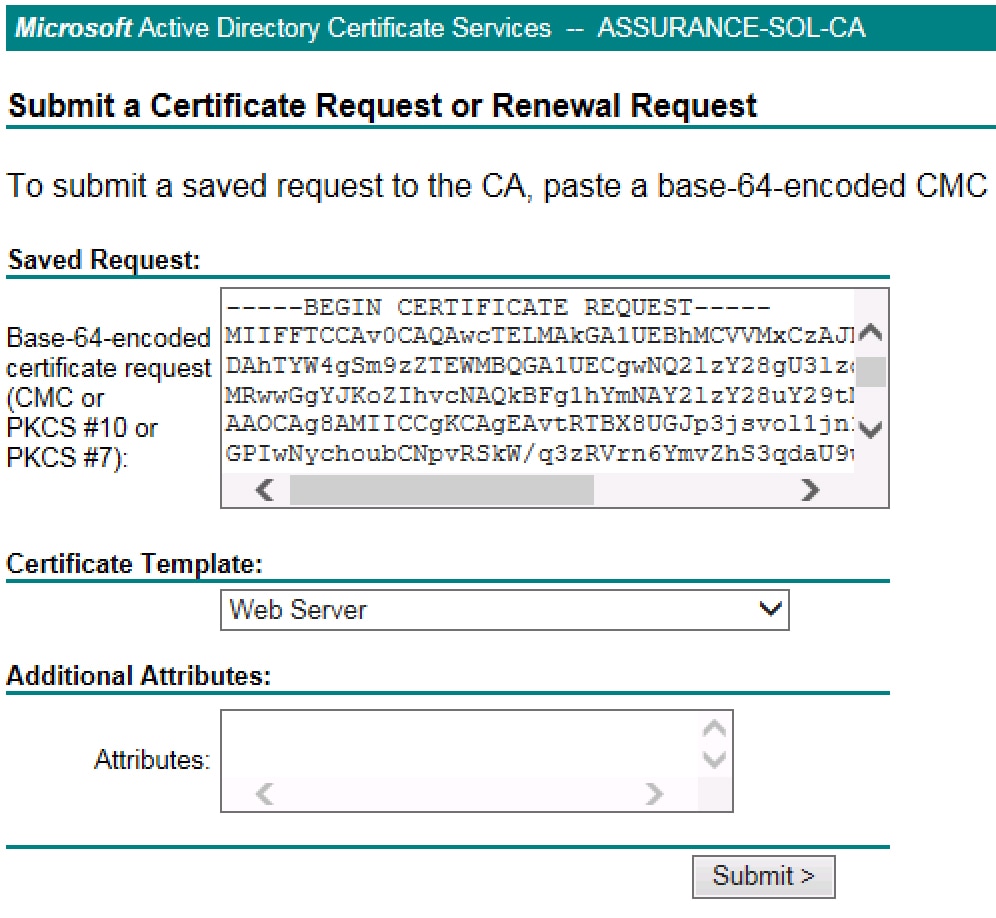
Ensure that the certificate template you select is configured for both client and server authentication, as illustrated in the extendedKeyUsage line in Step 2's openssl.cnf file example. |
Step 7 | Proceed to gather the issued certificate and its issuer CA chain. |
Step 8 | If the certificate issuer provides the certificate full chain (server and CA) in p7b, do these steps:
|
Step 9 | If the certificate issuer provides the certificate and its issuer CA chain in loose files, do these steps:
|
Step 10 | Import the csr.key and server-cert-chain.pem files to Catalyst Center:
|
Certificate configuration considerations
When creating the openssl.cnf configuration file for your Catalyst Center deployment, keep these considerations in mind:
- Pay close attention to the alt_names section, which must contain all DNS names (including the Catalyst Center FQDN) that are used to access Catalyst Center, either by a web browser or by an automated process such as PnP or Cisco ISE.
-
The alt_names section must contain Catalyst Center's FQDN (
DNS.1 = FQDN-of-Catalyst-Center) as the first DNS entry, and must match the Catalyst Center hostname (FQDN) that is set during Catalyst Center configuration through the configuration wizard (in the Cluster's hostname input field). You cannot add a wildcard DNS entry in place of Catalyst Center's FQDN, but you can use a wildcard in subsequent DNS entries in the alt-names section (for PnP and other DNS entries). For example, *.domain.com is a valid entry. Catalyst Center currently supports only one hostname (FQDN) for all interfaces. - Adjust default_bits and default_md if your certificate authority admin team requires 2048/sha256 instead.
- Specify values for every field in the req_distinguished_name and alt_names sections. The only exception is the OU field, which is optional. Omit the OU field if your certificate authority admin team does not require it.
- The emailAddress field is optional; omit it if your certificate authority admin team does not require it.
- In the extendedKeyUsage extension, the serverAuth attribute is mandatory. The clientAuth attribute is optional and only needed if you plan to use this certificate to connect to pxGrid in the Advanced Settings when adding the Cisco ISE server.
- If you are importing a self-signed certificate (not recommended), it must contain the X.509 Basic Constraints "CA:TRUE" extension, and the keyUsage extension must include keyCertSign.
- The less than symbol "<" that is vulnerable to cross site scripting (XSS) attack is not allowed in certificate fields.
Sample configuration files
Refer to this example of openssl.cnf configuration file and make the changes necessary to suit your deployment.
ImportantEnsure that digitalSignature is specified for the certificate's keyUsage parameter.
Example of openssl.cnf with IP or FQDN
req_extensions = v3_req
distinguished_name = req_distinguished_name
default_bits = 4096
default_md = sha512
prompt = no
[req_distinguished_name]
C = <two-letter-country-code>
ST = <state-or-province>
L = <city>
O = <company-name>
OU = MyDivision
CN = FQDN-of-Catalyst-Center
emailAddress = responsible-user@mycompany.tld

[ v3_req ]
basicConstraints = CA:FALSE
keyUsage = digitalSignature, keyEncipherment
extendedKeyUsage=serverAuth,clientAuth
subjectAltName = @alt_names
[alt_names]
DNS.1 = FQDN-of-Catalyst-Center
DNS.2 = pnpserver.DomainAssignedByDHCPDuringPnP.tld
DNS.3 = *.domain.com
PKI certificate authority
To establish an HTTPS connection with Catalyst Center, you must use its server CA to confirm its identity and complete authentication. In addition to the server CA, Catalyst Center also makes use of a public key infrastructure (PKI) CA (configured as either a root or subordinate CA) to establish client connections. When you use the PKI CA, choose a different realm trust (signing CA) than the one associated with Catalyst Center’s server CA.
Change the role of the certificate authority from root to subordinate
The device CA, a private CA that is provided by Catalyst Center, manages the certificates and keys that are used to establish and secure server-client connections. To change the role of the device CA from a root CA to a subordinate CA, complete this procedure.
You can change the role of the private (internal) Catalyst Center CA from a root CA to a subordinate CA using the Certificate Authority window in the GUI. When making this change:
- If you want to have Catalyst Center act as a subordinate CA, ensure that you have a root CA, for example, Microsoft CA, and agree to use its certificate.
- As long as the subordinate CA is not fully configured, Catalyst Center continues to operate as an internal root CA.
-
Generate a Certificate Signing Request file for Catalyst Center and ensure it is manually signed by your external root CA, as described in this procedure.
Note
Catalyst Center continues to run as an internal root CA during this time period.
- After the Certificate Signing Request is signed by the external root CA, this signed file must be imported back into Catalyst Center using the GUI (as described in this procedure). After the import, Catalyst Center initializes itself as the subordinate CA and provides all the existing functionalities of a subordinate CA.
- When you switch a CA's role from root to subordinate, the old CA is retired and the new subordinate CA's PKI chain takes over. The revocation list is published by a CA, and after the CA is retired, revocation is moot since trust cannot be established. If your organization's policy mandates that unused certificates are revoked first, you can revoke the certificate from the GUI's Device Certificates window before switching the CA's role from root to subordinate. Device controllability (enabled by default) will automatically update the device with a new certificate chain, sourced from the subordinate CA. New telemetry connections would only authenticate with this new certificate chain, which aligns with the trusted subordinate CA on the authenticator side.
- The subordinate CA certificate lifetime displayed in the GUI is read directly from the certificate and is not calculated using the system time. Therefore, if you install a certificate with a lifespan of 1 year today and look at it in the GUI the same time next year, the GUI will still show that the certificate has a 1-year lifetime.
- The subordinate CA certificate must be in PEM or DER format only.
- The subordinate CA does not interact with the higher CAs; therefore, it is not aware of revocation, if any, of the certificates at a higher level. Because of this, any information about certificate revocation is also not communicated from the subordinate CA to the network devices. Because the subordinate CA does not have this information, all the network devices use only the subordinate CA as the CRL Distribution Points (CDP) source.
- Consider that if you use EAP-Transport Level Security (EAP-TLS) authentication for AP profiles in Plug and Play (PnP), you cannot use a subordinate CA. You can only use a root CA.
Before you begin
You must have a copy of the root CA certificate.
Step 1 | From the main menu, choose . |
Step 2 | Click the CA Management tab. |
Step 3 | Review the existing root or subordinate CA certificate configuration information from the GUI:
|
Step 4 | In the CA Management tab, click Enable SubCA Mode button. |
Step 5 | Review the warnings that display: For example,
|
Step 6 | Click OK to proceed. |
Step 7 | Drag and drop your root CA certificate into the Import External Root CA Certificate Chain field and click Upload. The root CA certificate is uploaded into Catalyst Center and used to generate a Certificate Signing Request. After the upload process finishes, a |
Step 8 | Click Next. Catalyst Center generates and displays the Certificate Signing Request. |
Step 9 | View the Catalyst Center-generated Certificate Signing Request in the GUI and do one of these actions:
|
Step 10 | Send the Certificate Signing Request file to your root CA. Your root CA will then return a subordinate CA file, which you must import back into Catalyst Center. |
Step 11 | After receiving the subordinate CA file from your root CA, access the Catalyst Center GUI again and return to the Certificate Authority window. |
Step 12 | Click the CA Management tab. |
Step 13 | Click Yes for the Change CA mode button. After clicking Yes, the GUI view with the Certificate Signing Request display. |
Step 14 | Click Next. The Certificate Authority window displays the Import SubCA Certificate field. |
Step 15 | Drag and drop your subordinate CA certificate into the Import SubCA Certificate field and click Apply. The subordinate CA certificate is uploaded into Catalyst Center. After the upload finishes, the GUI displays the subordinate CA mode under the CA Management tab. |
Step 16 | Review the fields under the CA Management tab:
|
Provision a rollover subordinate CA certificate
Catalyst Center lets you apply a subordinate certificate as a rollover subordinate CA when 70 percent of the existing subordinate CA lifetime has elapsed.
Before you begin
- To initiate subordinate CA rollover provisioning, you must have changed the certificate authority role to subordinate CA mode. Refer to Change the role of the certificate authority from root to subordinate.
- 70 percent or more of the lifetime of the current subordinate CA certificate must have expired. When this occurs, Catalyst Center displays a Renew button under the CA Management tab.
- You must have a signed copy of the rollover subordinate CA certificate.
Step 1 | From the main menu, choose . |
Step 2 | In the CA Management tab, review the CA certificate configuration information:
|
Step 3 | Click Renew. Catalyst Center uses the existing subordinate CA to generate and display the rollover subordinate CA Certificate Signing Request. |
Step 4 | View the generated Certificate Signing Request in the GUI and do one of these actions:
|
Step 5 | Send the Certificate Signing Request file to your root CA. Your root CA will then return a rollover subordinate CA file that you must import back into Catalyst Center. The Certificate Signing Request for the subordinate CA rollover must be signed by the same root CA who signed the subordinate CA you imported when you switched from RootCA mode to SubCA mode. |
Step 6 | After receiving the rollover subordinate CA file from your root CA, return to the Certificate Authority window. |
Step 7 | Click the CA Management tab. |
Step 8 | Click Next in the GUI in which the Certificate Signing Request displays. The Certificate Authority window displays the Import Sub CA Certificate field. |
Step 9 | Drag and drop your subordinate rollover CA certificate into the Import Sub CA Certificate field and click Apply. The rollover subordinate CA certificate is uploaded into Catalyst Center. After the upload finishes, the GUI changes to disable the Renew button under the CA Management tab. |
Configure the device certificate lifetime
Catalyst Center lets you change the certificate lifetime of network devices that the private (internal) Catalyst Center CA manages and monitors. The Catalyst Center default value for the certificate lifetime is 365 days. After the certificate lifetime value is changed using the Catalyst Center GUI, network devices that subsequently request a certificate from Catalyst Center are assigned this lifetime value.
NoteThe device certificate lifetime value cannot exceed the CA certificate lifetime value. Also, if the remaining lifetime of the CA certificate is less than the configured device's certificate lifetime, the device receives a certificate lifetime value equal to the remaining CA certificate lifetime.
Step 1 | From the main menu, choose . |
Step 2 | Review the device certificate and the current device certificate lifetime. |
Step 3 | In the Device Certificates window, click Modify. |
Step 4 | In the Device Certificates Lifetime dialog box, enter the new value in days. |
Step 5 | Click Save. |
DigiCert certificate distrust
On the dates specified by DigiCert, Mozilla and other organizations that use the affected certificate libraries will stop trusting active end-entity certificates that chain up to the distrusted CA roots, even if those certificates are not yet distrusted.
For more information, refer to DigiCert Root and Intermediate CA Certificate Updates 2023.
|
Certificate authority |
Distrust (expiry) date |
Distrust date for TLS |
|---|---|---|
|
Assured ID root CA |
2031-11-10 |
2026-04-15 |
|
DigiCert global root CA |
2031-11-10 |
2026-04-15 |
|
Scenario |
Impact |
Resolution |
|---|---|---|
|
You upload an impacted certificate as a Catalyst Center controller certificate. |
Browsers that use Mozilla refuse to connect via HTTPS to Catalyst Center. |
Procure a new third-party certificate for the certificate authority that does not use a distrusted CA root. |
|
Certificate validation logic does not consider that distrusted certificates could be rejected by the browser. |
When you upload a controller certificate, the certificate isn't considered invalid until the certificate is distrusted. |
Confirm that your controller certificate is not from a distrusted CA root. |
|
You integrate external services with Catalyst Center and you use an impacted certificate for the external service. |
Browsers that use Mozilla refuse to connect via HTTPS to external services. When you procure a new certificate for external services, Catalyst Center must re-establish HTTPS trust. |
Procure a new third-party certificate for external services and reintegrate with the external services. |
|
The trusted certificate UI doesn't indicate that a distrusted CA is invalid. The certificate remains green until it is distrusted. |
The Cisco trust bundle comes with a distrusted CA, which serves as legacy support. |
Add or remove the CA from . In an air-gapped environment, import the replacement CA (because you won't get new CA updates from the cloud). |
|
The Stealthwatch cloud migrates off a CA on the distrusted list. |
Provision the device with CA on the distrusted list for the Stealthwatch cloud connection. |
Replace the CA as explained at this link. |
Catalyst Center trustpool support
Catalyst Center and Cisco IOS devices support a special PKI certificate store that is known as trustpool. The trustpool holds X.509 certificates that identify trusted CAs. Catalyst Center and the devices in the network use the trustpool bundle to manage trust relationships with each other and with these CAs. Catalyst Center manages this PKI certificate store. An administrator (ROLE_ADMIN) can update it through the Catalyst Center GUI when the certificates in the pool are due to expire, are reissued, or must be changed for other reasons.
NoteCatalyst Center also uses the trustpool functionality to determine whether any certificate file that is uploaded through its GUI is a valid trustpool CA-signed certificate.
Catalyst Center contains a preinstalled, default Cisco-signed trustpool bundle named ios.p7b. This trustpool bundle is trusted by supported Cisco network devices natively, because it is signed with a Cisco digital signing certificate. This trustpool bundle is critical for the Cisco network devices to establish trust with services and applications that are genuine. This Cisco PKI trustpool bundle file is available at https://www.cisco.com/security/pki/.
To access the Catalyst Center PnP functionality, the supported Cisco devices that are managed and monitored by Catalyst Center must import the Cisco PKI trustpool bundle file. When the supported Cisco devices boot for the first time, they contact Catalyst Center to import this file.
The Catalyst Center trustpool management feature operates in this manner:
- You boot the Cisco devices that support the PnP functionality within your network. Not all Cisco devices support PnP. Refer to the Cisco Catalyst Center Compatibility Matrix for a list of supported Cisco devices.
- As part of the initial PnP flow, the supported Cisco devices download a trustpool bundle directly from Catalyst Center using HTTP.
-
The Cisco devices are now ready to interact with Catalyst Center to obtain further device configuration and provisioning according to the PnP traffic flows.
Note that if an HTTP proxy gateway exists between Catalyst Center and these Cisco devices, you must import the proxy gateway certificate into Catalyst Center.
Note
At times, you might need to update the trustpool bundle to a newer version due to some certificates in the trustpool expiring, being reissued, or for other reasons. Whenever the trustpool bundle needs to be updated, update it by using the Catalyst Center GUI. Catalyst Center can access the Cisco cloud (where the Cisco-approved trustpool bundles are located) and download the latest trustpool bundle. After download, Catalyst Center then overwrites the current or older trustpool bundle file. As a best practice, update the trustpool bundle before importing a new certificate from a CA.
Check the PnP certificate requirement
This section explains how to check the certificate on the PnP agent of Cisco IOS and Cisco IOS XE devices during a zero-touch deployment.
The certificate that is provided by Catalyst Center (running as PnP server) must contain a valid Subject Alternative Name (SAN) field to verify the server identity.
The check is applied to the server's DNS name or the IP address that is used in the PnP profile settings:
pnp profile SOME_NAME
transport https ipv4 IP_ADDRESS port 443

pnp profile SOME_NAME
transport https host DNS_NAME port 443
The enforcement is applied by comparing the SAN field of the certificate to the value used in the PnP profile that is configured on the device.
This table summarizes the enforcement that is applied:
| PnP profile configuration | Certificate requirement |
|---|---|
|
DHCP Option-43 or Option-17 discovery of the PnP server using an explicit IPv4 or IPv6 address. |
The SAN field of the server certificate must contain the explicit IPv4 or IPv6 address used in Option-43 or Option-17. |
|
DHCP Option-43 or Option-17 discovery of the PnP server using a DNS name. |
The SAN field of the server certificate must contain the specific DNS name. |
|
DNS discovery of the PnP server. |
The SAN field of the server certificate must contain pnpserver.<local-domain>. |
|
Cisco.com discovery of the PnP Server. |
One of these conditions is applicable:
|
|
Day-2 (manual configuration) PnP profile creation. |
The SAN field of the server certificate must contain either the IP address or the DNS name that is used in the PnP profile configuration. |
We recommend that you use a discovery method based on the DNS name because the functionality is not affected by changes to the IP address.
Step 1 | Use the PnP service logs to diagnose the problem. Check whether the HTTPS connection is established with the device after the trustpoint is installed on the device. The PnP service logs show that the device moves from the CERTIFICATE_INSTALL_REQUESTED stage to the FILESYSTEM_INFO_REQUESTED stage, but no further progress is made. For example: Thereafter, PnP provisioning fails with an error that is similar to this example: |
Step 2 | For device-side debugging, use these recommended outputs to determine whether the issue is related to the server ID check: |
Step 3 | Enable debugging before you initiate a PnP discovery. |
Step 4 | Check the server certificate's SAN field by entering this command from the CLI of a Linux workstation or a Mac terminal. Be sure to replace SERVER_IP with your Catalyst Center cluster address. |
Step 5 | In the output, pay close attention to the X509v3 extensions, especially the X509v3 Subject Alternative Name, which is the field that must be matched against Catalyst Center (running as a PnP server) details. The output is similar to this example: |
Step 6 | Depending on the type of certificate you are using, do one of these tasks:
|
Certificates for systems that peer with Catalyst Center
When setting up a certificate for an external system that Catalyst Center communicates with (such as Cisco ISE, IPAM, or Stealthwatch Security Analytics), ensure that the HTTP-type CRL distribution point is supported and is placed before LDAP (if multiple distribution points with LDAP are present) for the system's certificates.
If you don't place the CRL distribution point before LDAP, authentication with the external system might fail for LDAP-type CRL entries.
Enable or disable SFTP compatibility mode
SSH File Transfer Protocol (SFTP) Compatibility mode allows legacy network devices to connect to Catalyst Center using older cipher suites that are not secure. By default, SFTP Compatibility mode is enabled for new Catalyst Center deployments.
- If your network does not have legacy devices, we recommend that you disable SFTP Compatibility mode during initial cluster configuration.
- If your network has legacy devices, we recommend that you enable SFTP Compatibility mode for a maximum of three days. This duration gives enough time to complete provisioning tasks.
ImportantThese algorithms are enabled when SFTP Compatibility mode is enabled on port 22 of a Catalyst Center appliance running version 2.3.7.6 or later:
- Key exchange (KEX) algorithms: diffie-hellman-group1-sha1, diffie-hellman-group-exchange-sha1, diffie-hellman-group14-sha1
- SSH server host key algorithms: ssh-dss
- Encryption algorithms: aes128-cbc, aes192-cbc, aes256-cbc
- Message Authentication Code (MAC) algorithms: hmac-sha2-256-etm, hmac-sha2-512-etm, hmac-sha1-etm, hmac-sha1, hmac-sha1-96
To enable or disable SFTP Compatibility mode, complete these steps:
Step 1 | From the main menu, choose . |
Step 2 | In the Host column, locate the relevant server and click the corresponding i icon. A message appears, indicating whether SFTP Compatibility mode is currently enabled or disabled on that server. |
Step 3 | If necessary, click the link that is provided in the message to enable or disable this mode. |
Browser-based appliance configuration wizard
In addition to the appliance configuration wizard that has been available since its first release, Catalyst Center also provides a browser-based appliance configuration wizard. Refer to these topics for a description of how to disable or re-enable this wizard.
Disable the wizard
A self-signed certificate is provided with your Catalyst Center appliance. If your production environment does not allow the use of self-signed certificates, we recommend that you shut down the service that is associated with the browser-based appliance configuration wizard. Complete this procedure right after using the wizard to configure your appliance.
NoteOnly users with root privileges can complete this procedure.
Step 1 | In an SSH client, log in to your Catalyst Center appliance using the IP address that you entered during configuration. When prompted, enter your username and password. |
Step 2 | (Optional) Enter the maglev-config webinstall command to view the usage information for the commands that you must run to disable or re-enable the browser-based appliance configuration wizard. This output appears: |
Step 3 | Disable the browser-based configuration wizard by entering the maglev-config webinstall disable command. After the operation ends, you receive this message: |
Re-enable the wizard
If the browser-based configuration wizard is currently disabled on an appliance, re-enable it before you complete this task:
- Add nodes to a three-node Catalyst Center cluster on which you plan to enable high availability (HA).
- Remove a node from a three-node cluster that has HA enabled, and replace it with a new node. In this case, ensure that the browser-based configuration wizard is enabled on at least one of the other two cluster nodes.
NoteOnly users with root privileges can complete this procedure.
Step 1 | In an SSH client, log in to your Catalyst Center appliance using the IP address that you entered during configuration. When prompted, enter your username and password. |
Step 2 | Re-enable the wizard by running the maglev-config webinstall enable command. After the operation ends, you receive this message: |
Upgrade legacy devices
If you have legacy network devices, you must upgrade them to the latest device software:
- To view the software versions that Cisco SD-Access supports, refer to the Cisco SD-Access Compatibility Matrix.
- To view general device support information for Catalyst Center, refer to the Cisco Catalyst Center Compatibility Matrix.
Some devices, such as Cisco Aironet 1800 Series Access Points Version 8.5, use TLSV1, which is not secure. To upgrade the TLS version, you must upgrade the device software version to 8.8.
Secure network data
Catalyst Center lets you use the Data Anonymization feature to hide the identity of wired and wireless end clients in the Cisco Catalyst Assurance dashboard. For details, refer to "View or update collector configuration information" in the Cisco Catalyst Assurance User Guide.
Syslog management
Catalyst Center protects syslogs for user-sensitive data such as username, password, IP address, and so on.
View audit logs
Audit logs capture information about the various applications running on Catalyst Center. Audit logs also capture information about device public key infrastructure (PKI) notifications. The information in these audit logs can be used to help in troubleshooting issues, if any, involving the applications or the device CA certificates.
Audit logs also record system events that occurred, when and where they occurred, and which users initiated them. With audit logging, configuration changes to the system get logged in separate log files for auditing.
Step 1 | From the main menu, choose . The Audit Logs window opens, where you can view logs about the current policies in your network. These policies are applied to network devices by the applications installed on Catalyst Center. |
Step 2 | Click the timeline slider to specify the time range of data you want displayed on the window:
|
Step 3 | Click the arrow next to an audit log to view the corresponding child audit logs. Each audit log can be a parent to several child audit logs. By clicking the arrow, you can view a series of additional child audit logs. NoteAn audit log captures data about a task done by Catalyst Center. Child audit logs are subtasks to a task done by Catalyst Center. |
Step 4 | (Optional) From the list of audit logs in the left pane, click a specific audit log message. In the right pane, click . With the copied ID, you can use the API to retrieve the audit log message based on the event ID. The audit log displays the Description, User, Interface, and Destination of each policy in the right pane. NoteThe audit log displays northbound operation details such as POST, DELETE, and PUT with payload information, and southbound operation details such as the configuration pushed to a device. For detailed information about the APIs on Cisco DevNet, refer to Catalyst Center Platform Intent APIs. |
Step 5 | (Optional) Click Filter to filter the log by User ID, Log ID, or Description. |
Step 6 | Click the pencil icon to subscribe to the audit log events. A list of syslog servers is displayed. |
Step 7 | Check the syslog server check box that you want to connect to and click Save. NoteUncheck the syslog server check box to unsubscribe from the audit log events and click Save. |
Step 8 | In the right pane, use the Search field to search for specific text in the log message. |
Step 9 | From the main menu, choose to view the upcoming, in-progress, completed, and failed tasks (such as operating system updates or device replacements) and existing, pending-review, and failed work items. |
Export audit logs to syslog servers
Enabling syslogs for audit logs offers these benefits:
- Centralized logging: Collect and store logs in one place for easier monitoring.
- Security monitoring: Quickly detect unauthorized or suspicious activities.
- Compliance: Maintain tamper-proof records for audits and investigations.
You can export the audit logs from Catalyst Center to multiple syslog servers by connecting to them.
Before you begin
Configure the syslog servers in the area.
Step 1 | From the main menu, choose . |
Step 2 | At the top of the window, click the pencil icon. |
Step 3 | Select the syslog servers that you want to connect to and click Save. |
Step 4 | (Optional) To disconnect from a syslog server, deselect it and click Save. |
Use APIs to view audit logs in syslog servers
With the Catalyst Center platform, you can use APIs to view audit logs in syslog servers. Using the Create Syslog Event Subscription API from the Developer Toolkit, create a syslog subscription for audit log events.
Whenever an audit log event occurs, the syslog server lists the audit log events.
View the security advisories report
Catalyst Center provides the functionality to create a Security Advisory report that scans your Cisco network devices for relevant security advisories, and contains information about publicly reported vulnerabilities.
Security recommendation: We encourage you to periodically review and run this report to understand the impact of published Cisco security advisories that affect your network. You can take appropriate actions, if necessary.
The Security Advisories report displays device data and related advisory data, such as Device Name, IP Address, Device Type, Serial Number, Image Version, Site, Advisory ID, CVSS Score, and Impact.
Note- Each row in the report is a unique match of device and advisory because there can be a one-to-many relationship between devices and advisories.
- Devices that were not scanned are included in the report and labeled as not scanned.
- Devices that were scanned and have no advisories are labeled as no advisories found.
For more information, refer to "Run a security advisories report" in the Cisco Catalyst Center Platform User Guide.