Overview
Disaster recovery adds another layer of redundancy to safeguard against network downtime. It responds to a cluster failure by handing off network management duties to a connected cluster (referred to as a site going forward). Disaster recovery implementation on Catalyst Center consists of three components: the main site, the recovery site, and the witness site.
At any given time, the main and recovery sites are operating in either the active or standby role. The active site manages your network while the standby site maintains a continuously updated copy of the active site's data and managed services. Whenever an active site goes down, Catalyst Center automatically initiates a failover, completing the tasks necessary to designate the former standby site as the new active site.
These topics provide information about how to set up and use disaster recovery in your production environment.
Key terms
Key terms for understanding disaster recovery implementation on Catalyst Center include:
-
Main Site: The first site you configure when setting up your disaster recovery system. By default, it operates as the active site that manages your network. For information about how to configure the sites in your system, see Set up disaster recovery.
-
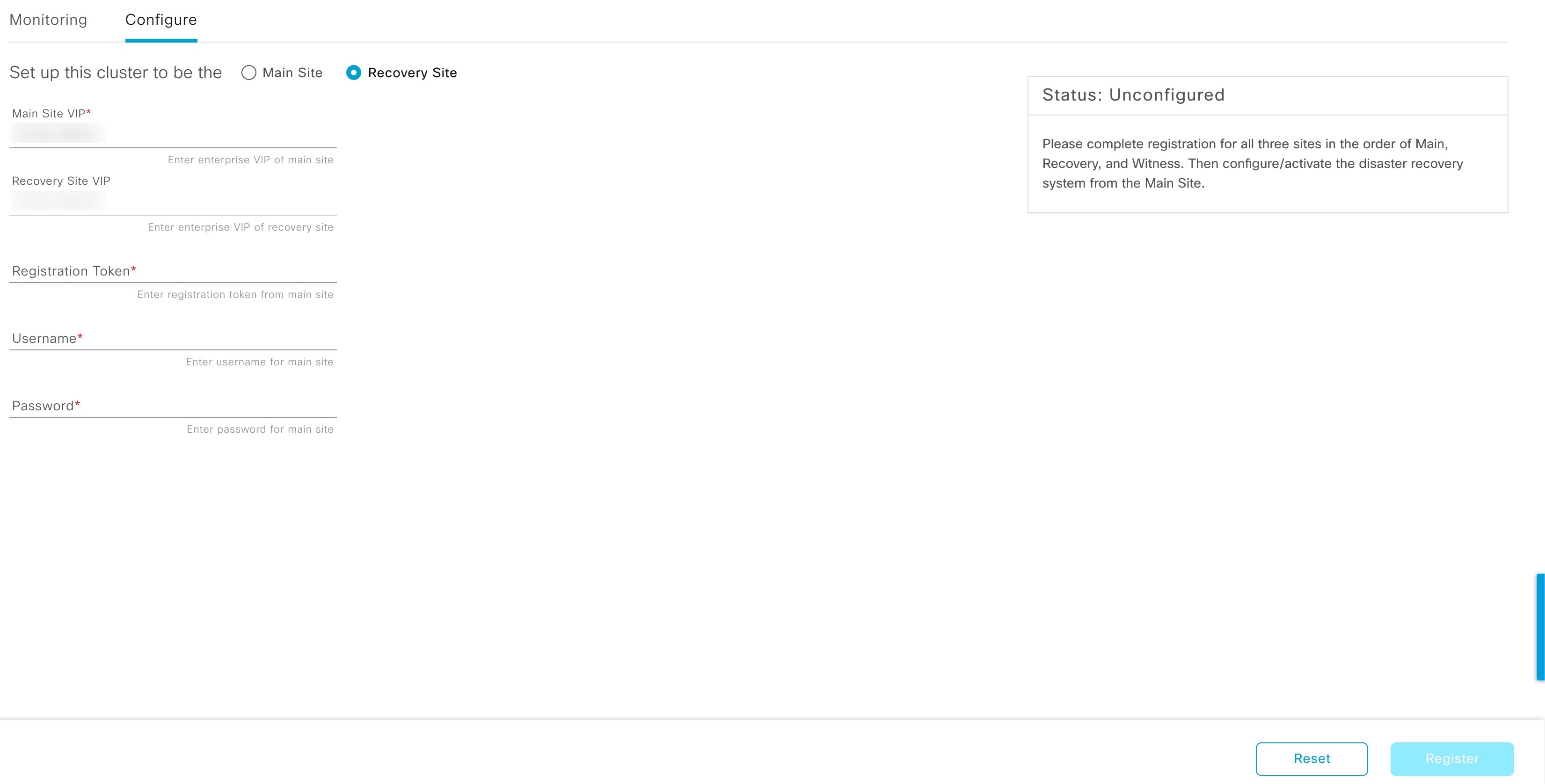
Recovery Site: The second site you configure when setting up your disaster recovery system. By default, it acts as your system's standby site.
-
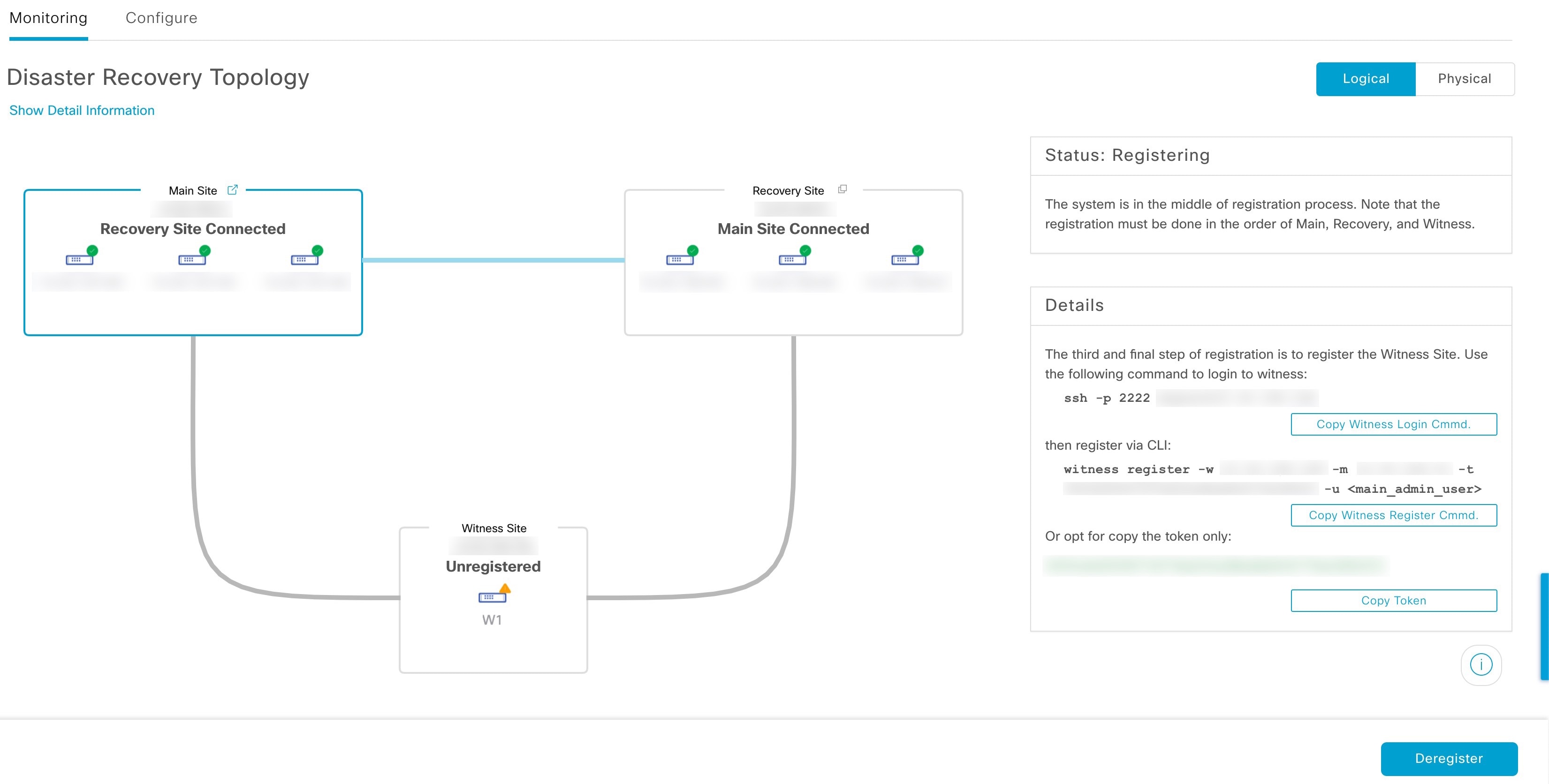
Witness Site: The third site you configure when setting up your disaster recovery system. This site, which resides on a virtual machine or separate server, is not involved with the replication of data or managed services. Its role is to give the current active site the quorum it needs to carry out disaster recovery tasks. This situation is known as a split-brain event, which can occur in a two-member system when the sites cannot communicate with each other. Each site thinks it should become active, which results in two active sites. Catalyst Center uses the witness site to arbitrate between the active and standby sites, allowing only one active site at any given time. For information about witness site requirements, see Prerequisites.
-
Register: To add a site to a disaster recovery system, you must first register it with the system by providing information such as your main site's VIP. When registering your recovery or witness site, you will also need to provide the token that is generated when you register your main site. For more information, see Set up disaster recovery.
-
Configure Active: The process of establishing a site as the active site, which involves tasks such as exposing the appropriate managed service ports.
-
Active site: The site that is currently managing your network. Catalyst Center continuously replicates its data to your standby site.
-
Configure Standby: The process of establishing a site as the standby site, which involves tasks such as configuring the replication of the active site's data and disabling the services which manage the network on the standby site.
-
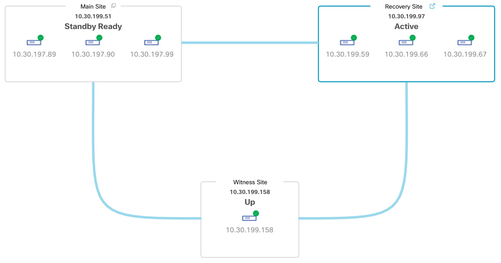
Standby Ready: When an isolated site meets the prerequisites to become a standby site, Catalyst Center moves it to this state. To establish this site as your system's standby site, click Rejoin in the Action area.
-
Standby site: The site that maintains an up-to-date copy of your active site's data and managed services. If your active site goes down, your system initiates a failover and your standby site takes over as the active site.

Note
A message will indicate when you are currently viewing your system's standby site. You need to initiate all disaster recovery tasks from the active site.
-
Failover: Catalyst Center supports two types of failover:
-
System-triggered: As soon as your active site goes down, Catalyst Center detect this and automatically performs the tasks required to establish your standby site as the new active site. You can monitor these tasks from the Event Timeline.
-
Manual: You can initiate a manual failover to designate the current standby site as the new active site. For more information, see Initiate a manual failover.
Important
-
After a failover, Assurance restarts and processes a fresh set of data on the new active site. Historical Assurance data from the former active site is not migrated over.
-
After a failover, the Catalyst Center inventory service triggers a full device sync. This can take anywhere from a few minutes to a few hours, depending on the number of devices that are managed. As is the case when Catalyst Center's normally scheduled device sync is running, you will not be able to provision devices on the newly activated cluster until the device sync triggered by a failover completes.
-
-
Isolate: During a failover, the former active site is separated from the disaster recovery system. Catalyst Center suspends its services and stops advertising its virtual IP address (VIP). From here, Catalyst Center completes the tasks necessary to establish the former standby site as the new active site.
-
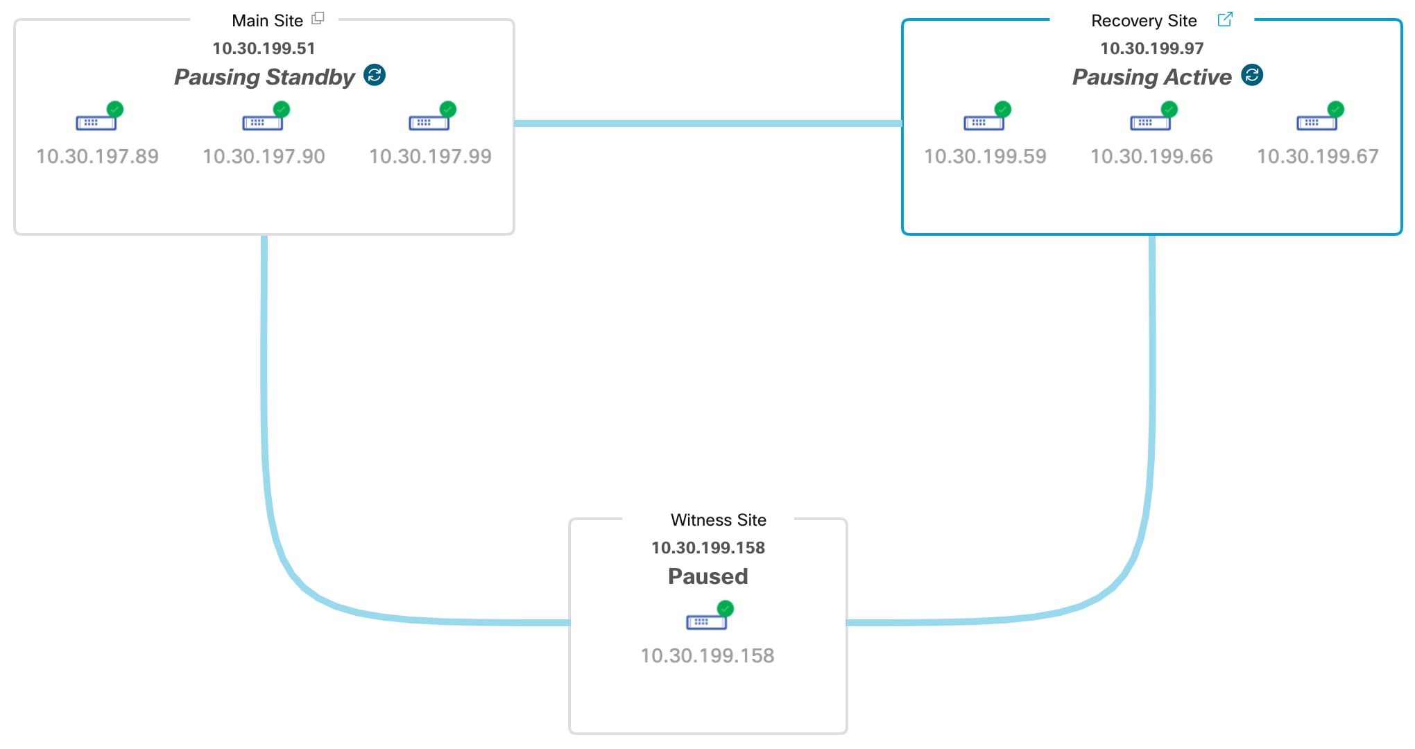
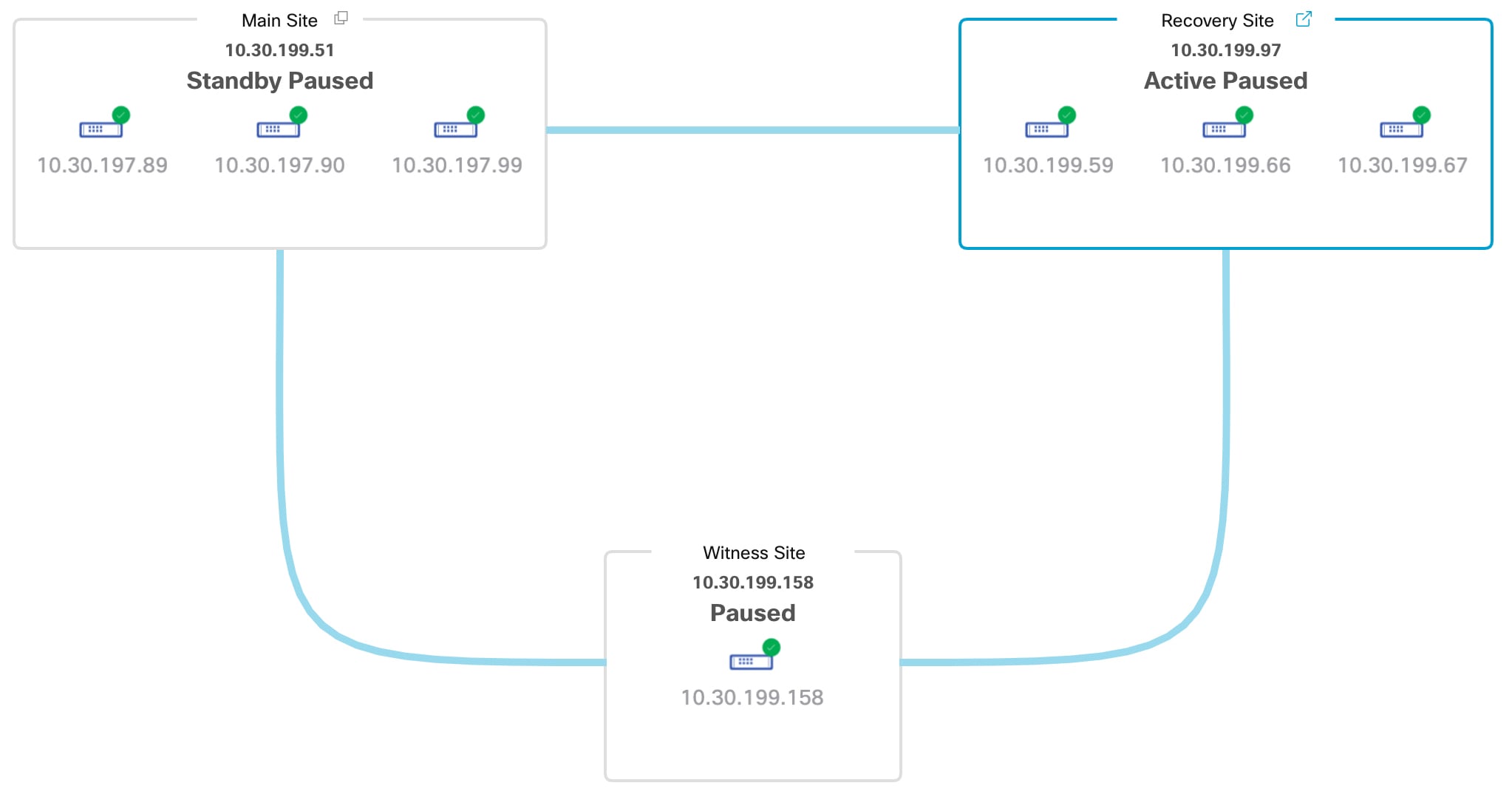
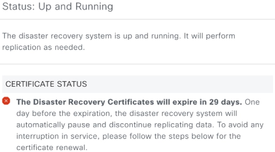
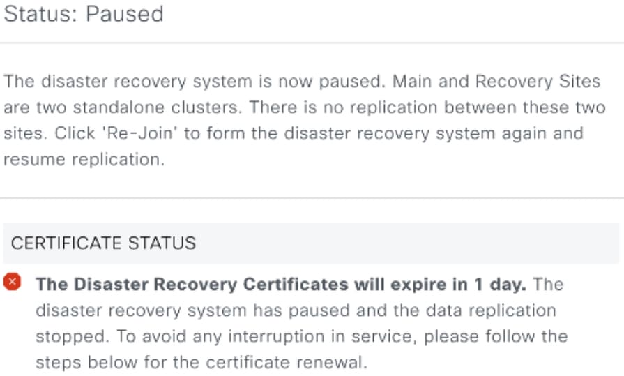
Pause: Temporarily suspend your disaster recovery system in order to separate the sites that make up your system and stop data and service replication. For more information, see Pause your disaster recovery system.
-
Rejoin: From the tab, click this button in the Action area in order to add a Standby Ready or Paused site back into a disaster recovery system as the new standby site (after a failover has taken place). You would also click this button in order to restart a disaster recovery system that is currently paused.
-
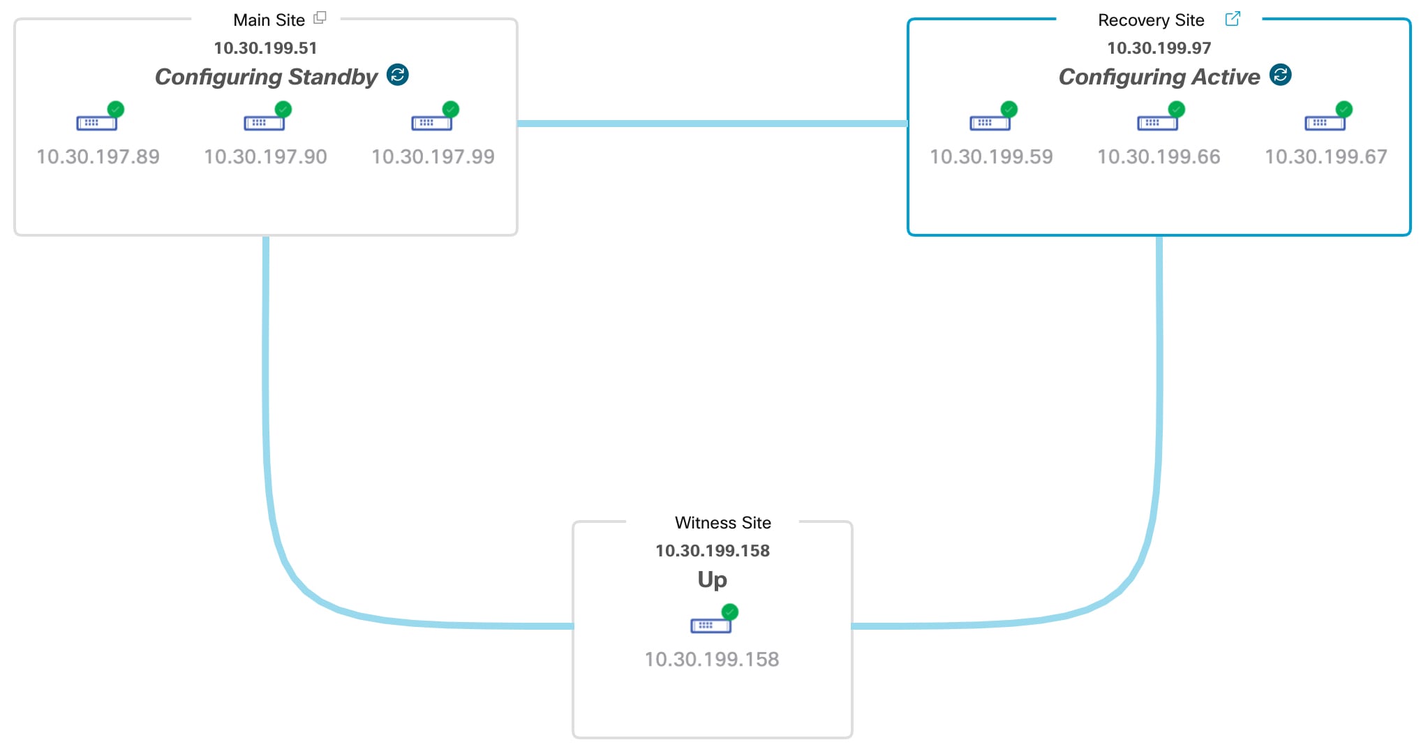
Activate DR: User-initiated operation that creates your system's active and standby sites. This operation entails setting up intracluster communication, verifying that the sites meet disaster recovery prerequisites, and replicating data between the two sites.
-
Deregister: Click this button in the Action area to remove the three sites you have configured for your disaster recovery system. You must do so in order to make changes to any of the site settings you have entered previously.
-
Retry: In the Action area, click this button in order to reinitiate any action that failed previously.
-
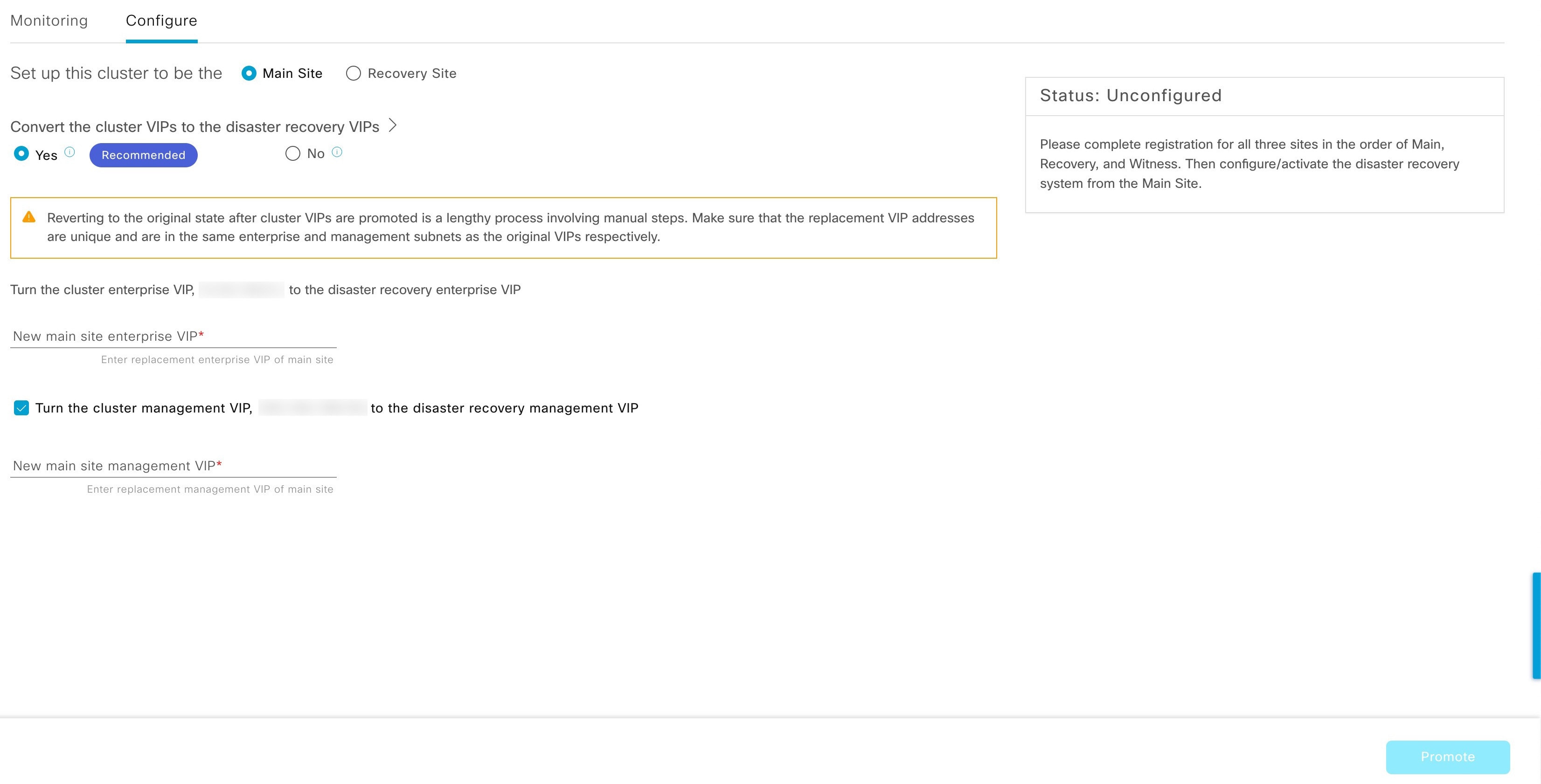
VIP Promotion: When this option is enabled, the Enterprise interface VIP configured for your Catalyst Center deployment is promoted for use as your system's disaster recovery VIP. For more information, see the "VIP Promotion" section in Main site registration considerations.
Data replication overview
The data replication process synchronizes data between your disaster recovery system’s main site and recovery site. The duration of the data replication process depends on several factors. These factors include the amount of data to be replicated, the network’s effective bandwidth, and the latency between the main and recovery sites. When disaster recovery is active for your Catalyst Center deployment, data replication does not affect operations or application use on the current active site, which manages your network.
Important |
After a failover, Assurance data from the failed site is not replicated. The site that becomes the new active site collects a new set of Assurance data. |
Either a full or incremental replication of data takes place, depending on which of these scenarios is applicable:
-
After initial activation: After the initial configuration and activation of your disaster recovery system, the recovery site does not have any data. In this scenario, a full replication of data between the main and recovery sites happens.
-
After a failover: Whenever the current active site fails, the disaster recovery system triggers a failover. In this scenario, a full data replication between the main and recovery sites occurs after the failed site rejoins the system.
-
During normal operation: This scenario will typically apply to your system. During its daily operation, changes that take place on the current active site are continuously synced with the current standby site.
Navigate the disaster recovery GUI
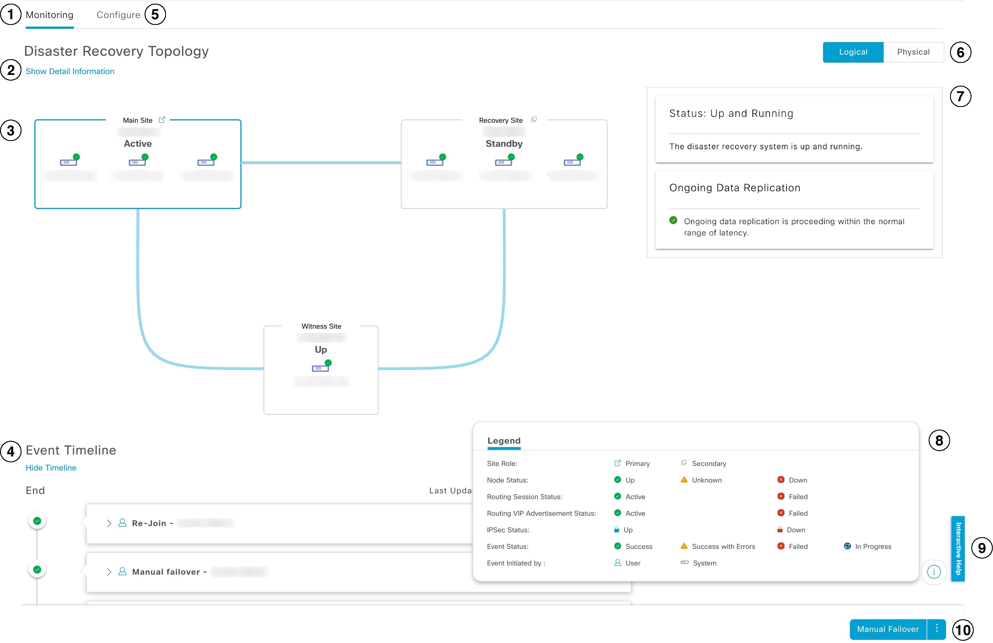
The table describes the components that make up the disaster recovery GUI for Catalyst Center and their function.
| Callout | Description |
|---|---|
|
1 |
Monitoring tab: Click to perform these actions:
|
|
2 |
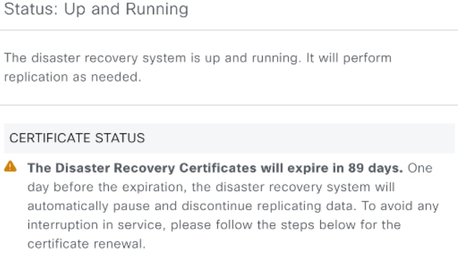
Show Detail Information link: Click to open the Disaster Recovery System slide-in pane. See View disaster recovery system status for more information. |
|
3 |
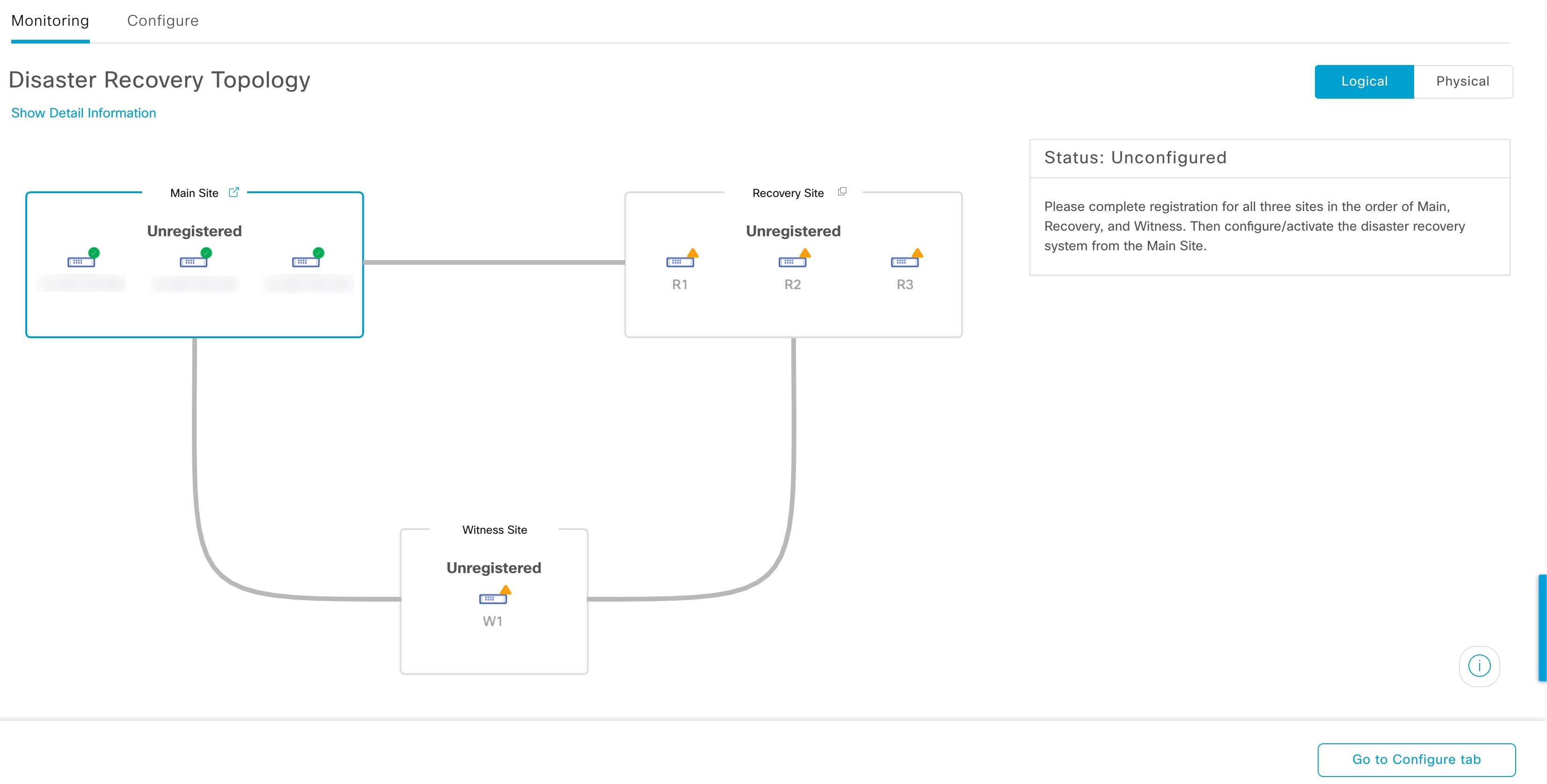
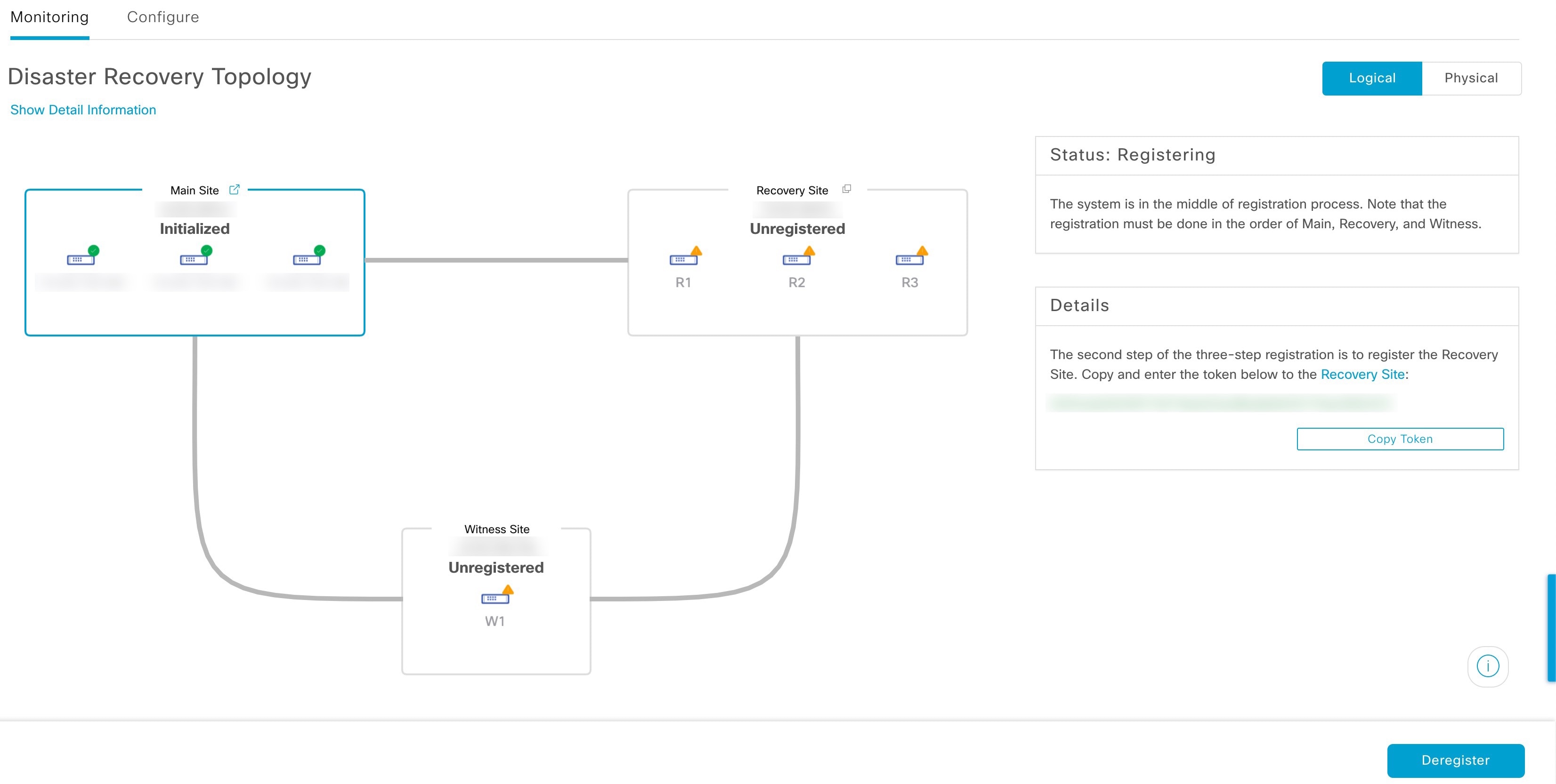
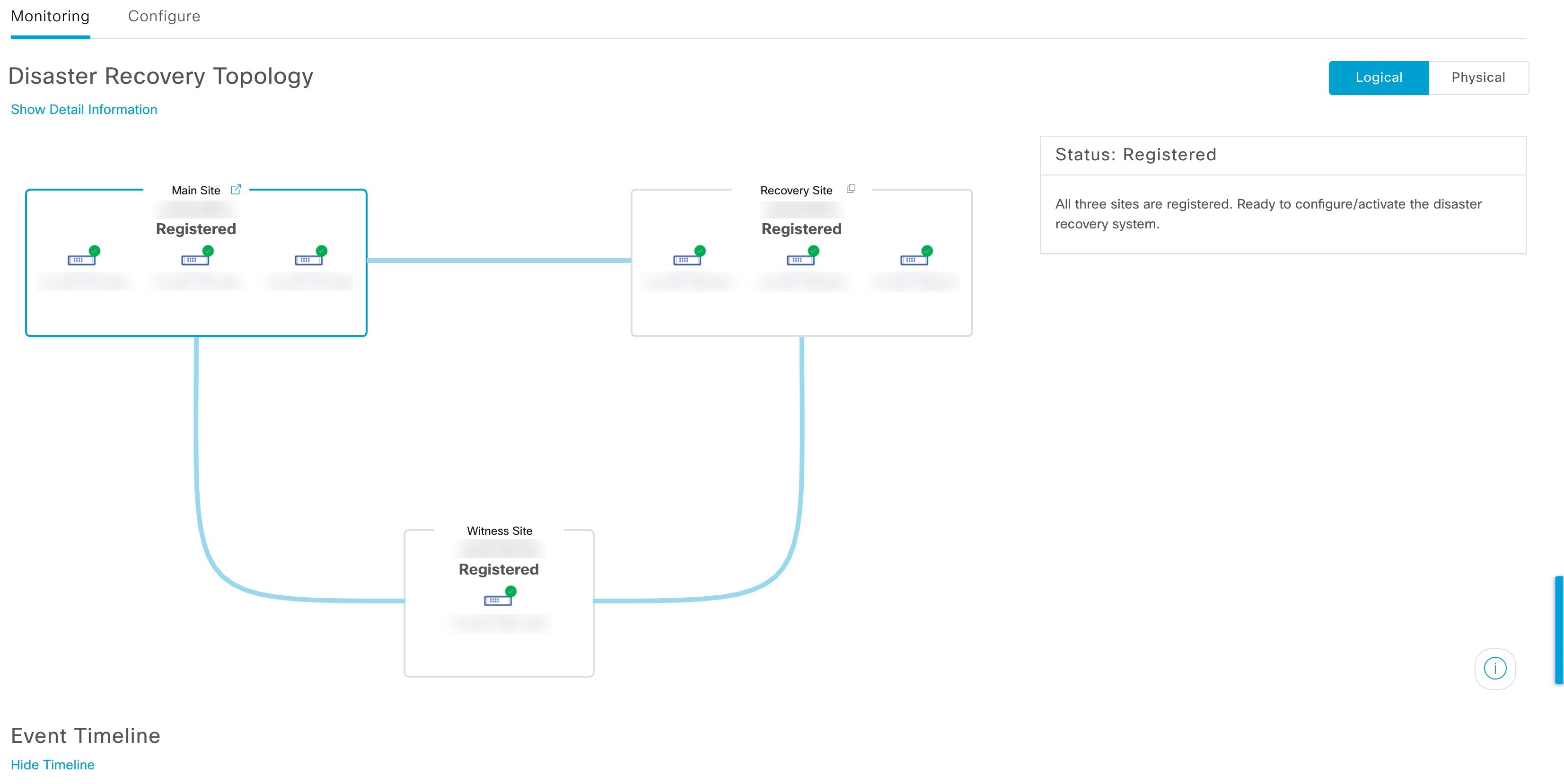
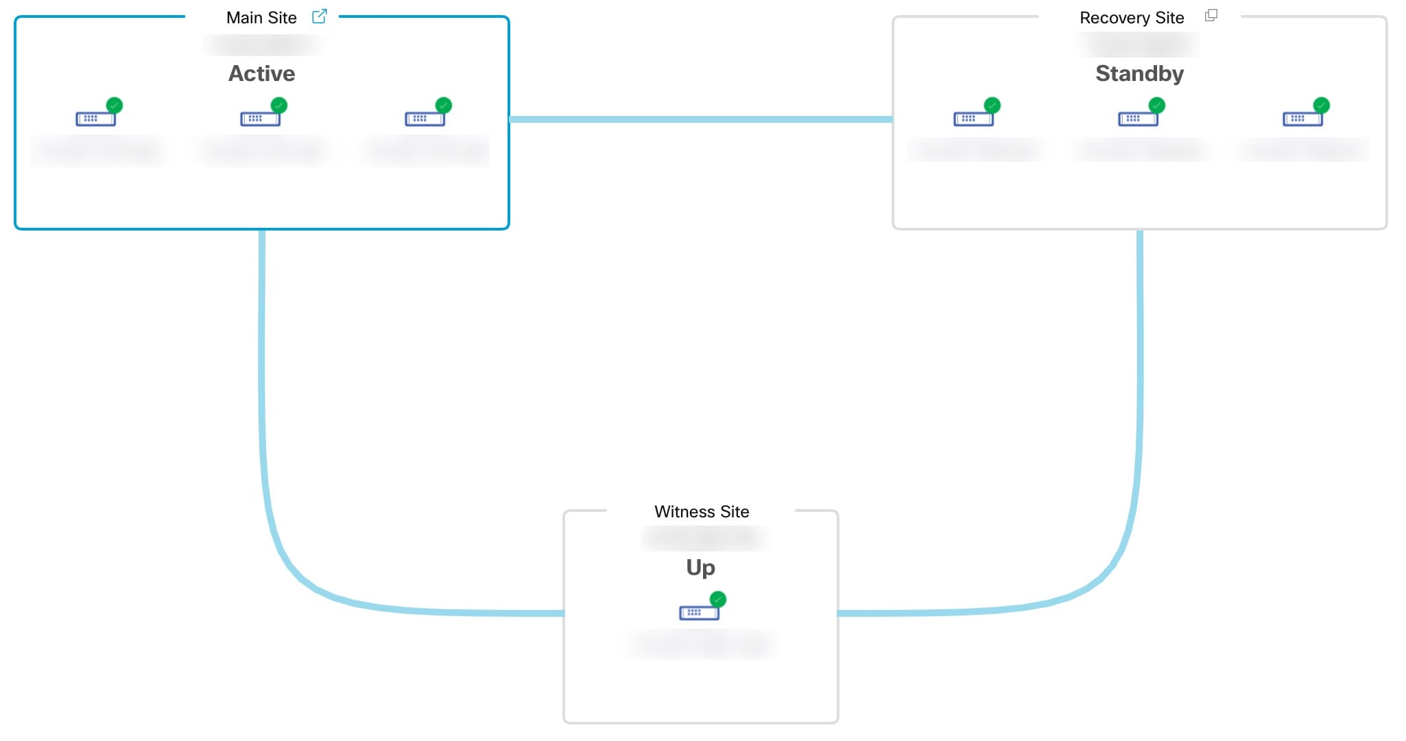
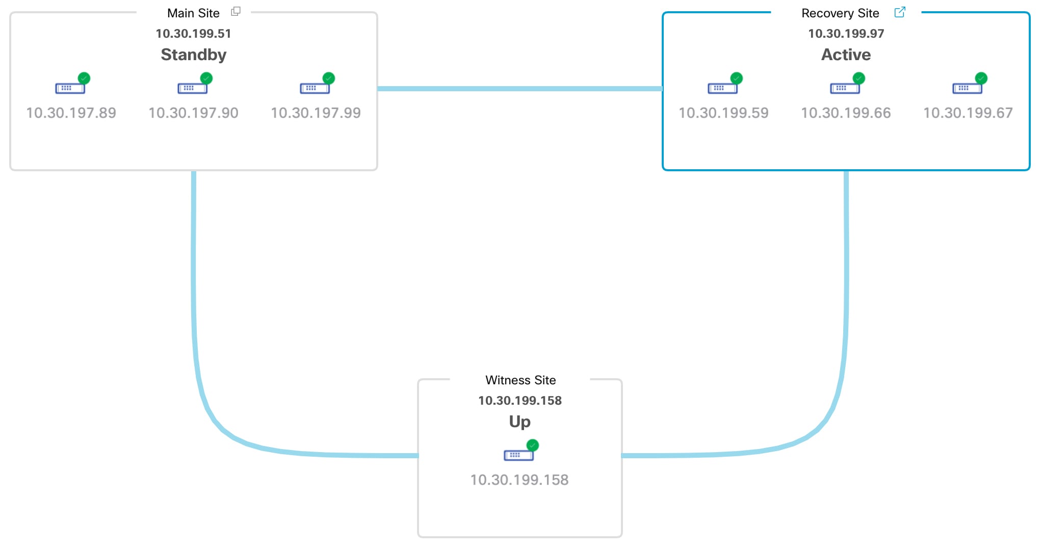
Topology: Displays either a logical or physical topology of your system and indicates the current status of your sites and their members.
|
|
4 |
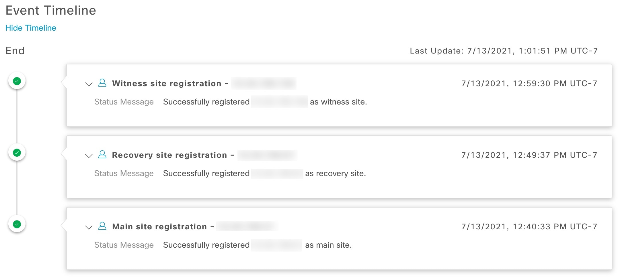
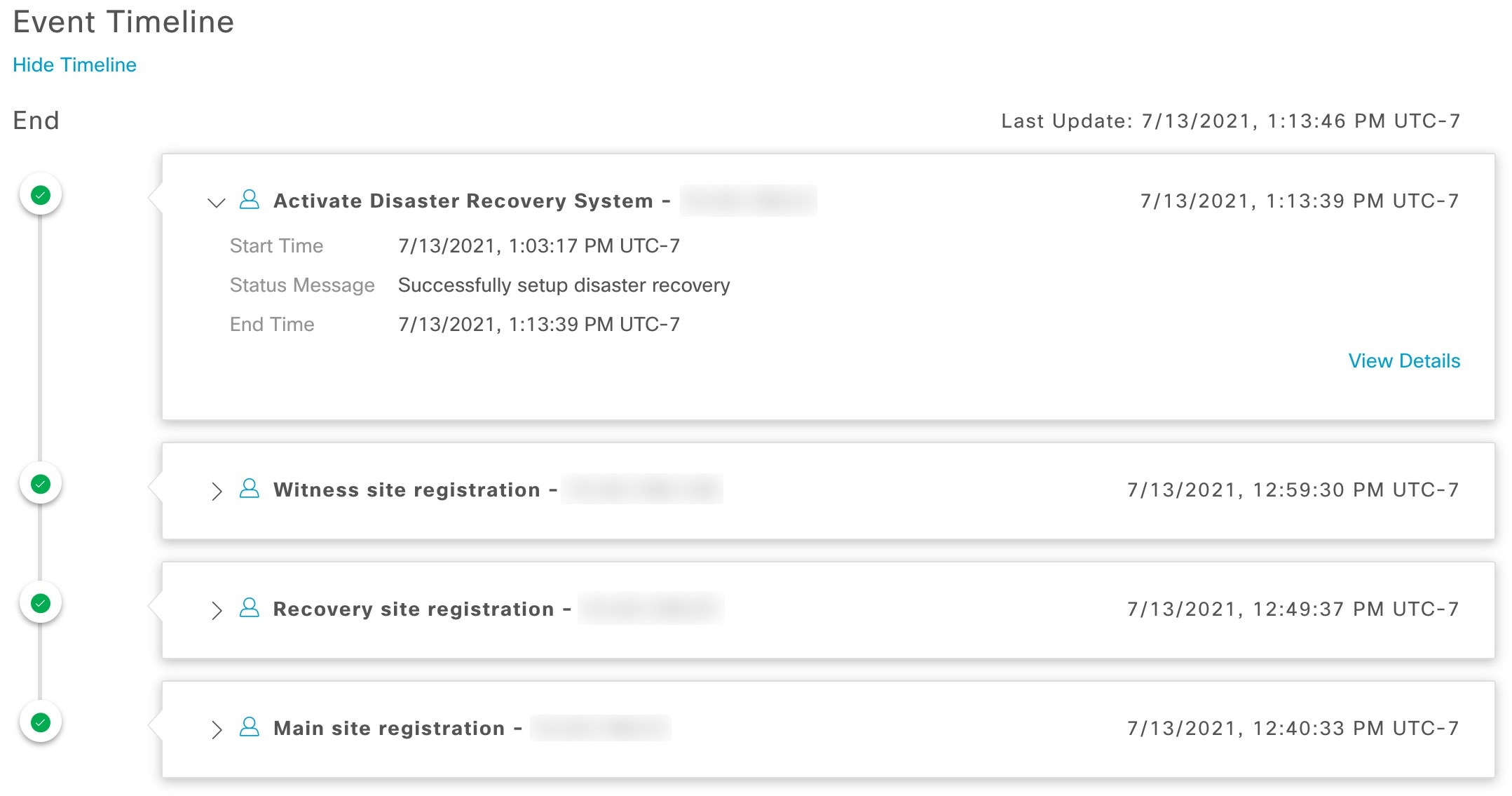
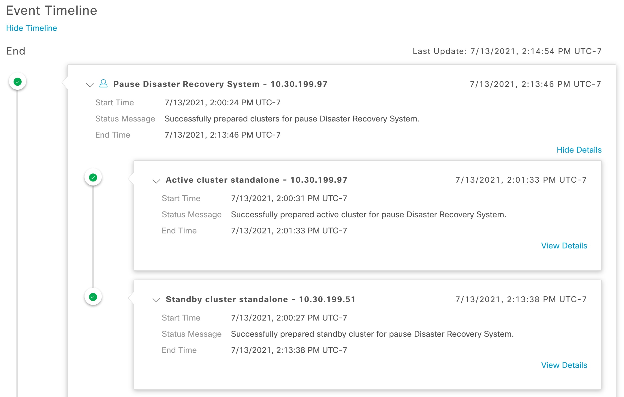
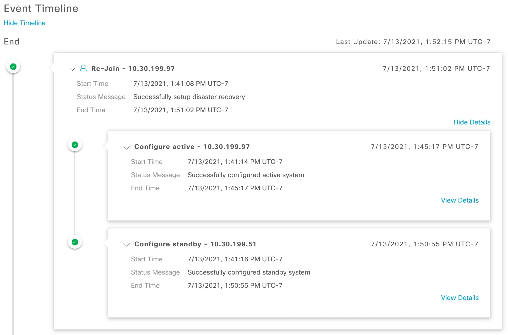
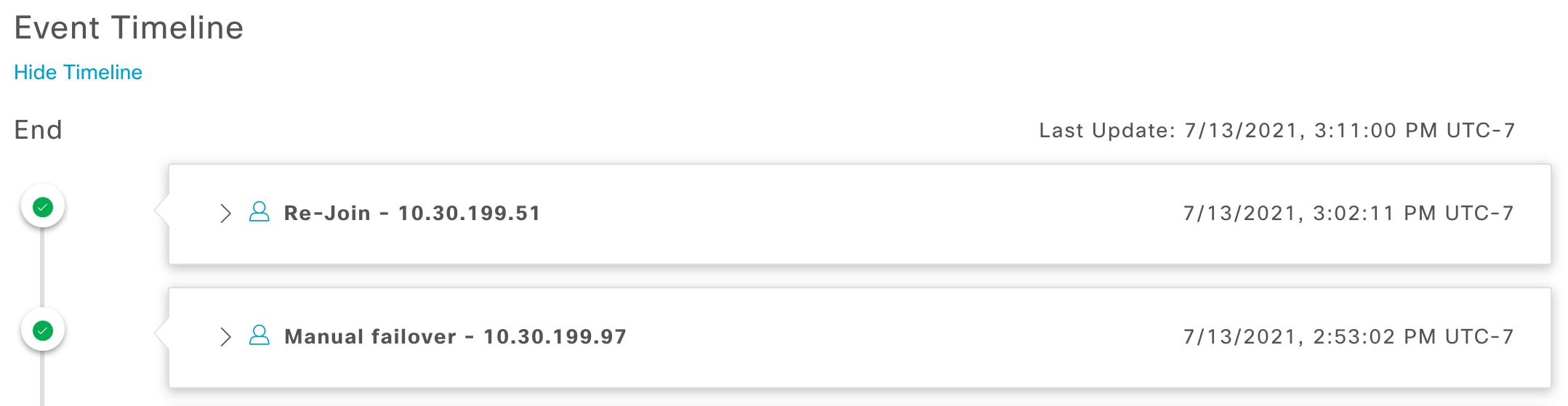
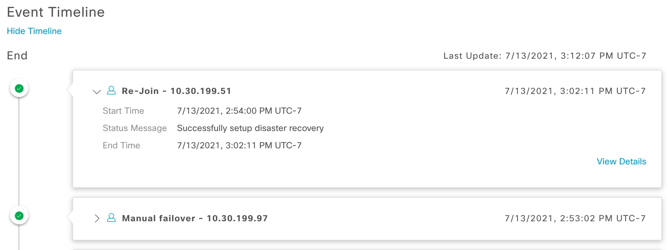
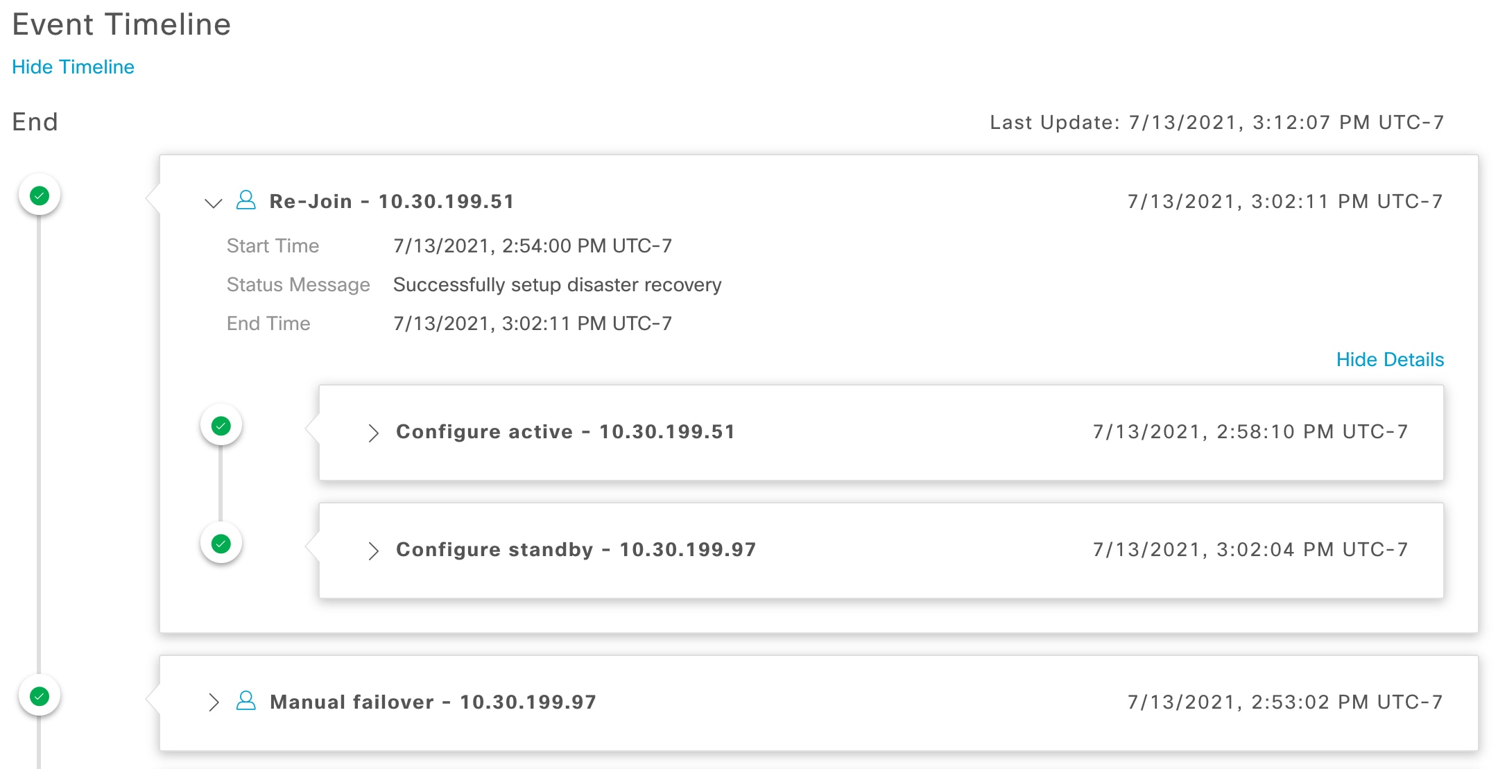
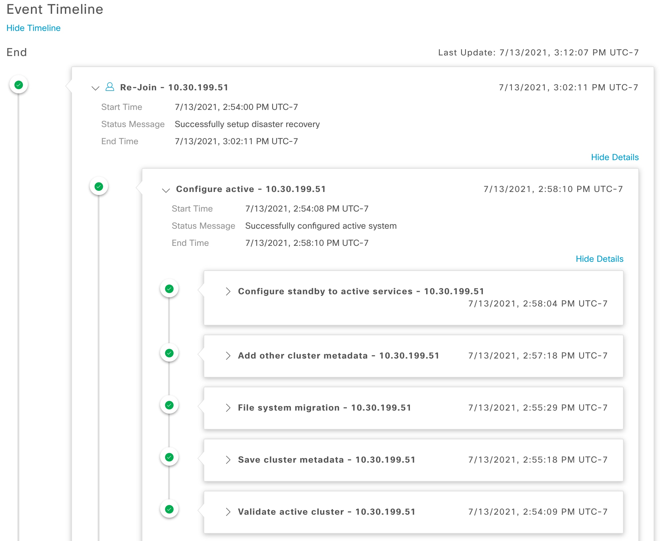
Event Timeline: Lists all disaster recovery tasks that are in progress or completed for your system. For more information, see Monitor the event timeline. |
|
5 |
Configure tab: Click to enter the settings necessary to establish a connection between the sites in your disaster recovery system. See Set up disaster recovery for more information. |
|
6 |
Logical and Physical tabs: Click the appropriate tab to toggle between a logical and physical topology of your system. |
|
7 |
|
|
8 |
Legend: Indicates what the topology icons represent. To view the legend, click |
|
9 |
Interactive Help button: Click to open a slide-in pane that provides links to walkthroughs that provide on-screen guidance to help you complete specific tasks in Catalyst Center. |
|
10 |
Action area: Displays the disaster recovery tasks you can initiate. Available tasks vary depending on your system's status and site configuration. |
View disaster recovery system status
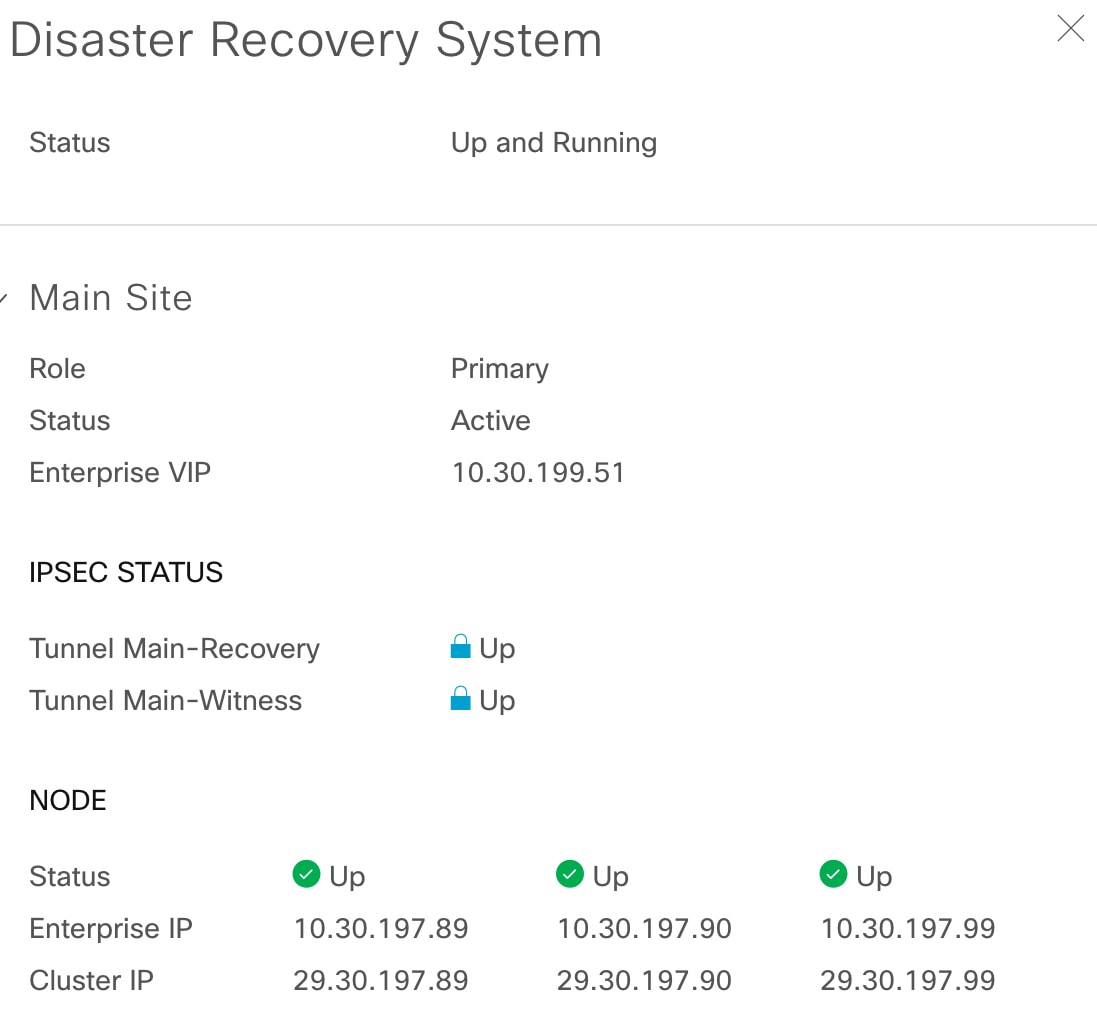
The topology provides a graphical representation of the current status of your disaster recovery system. To view this information in a table, use the Disaster Recovery System slide-in pane. To open this pane, complete one of these tasks:
-
Click the Show Detail Information link. Expand the site where you want to view the status in the slide-in pane.
-
In the topology, place your cursor over the Enterprise virtual IP address of a site or the icon of a specific node. In the dialog box that opens, click the link in the bottom-right corner.
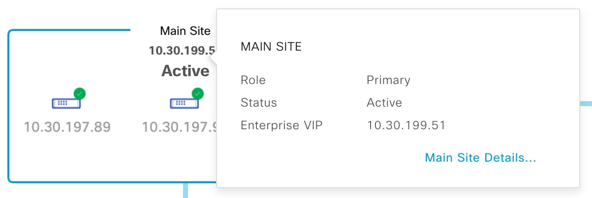
The slide-in pane opens and displays the relevant site information.


 Feedback