Managing and Monitoring Network Management Features

This feature module describes how to monitor, manage and deploy a variety of network management features, including Cisco Active Network Abstraction (ANA), Simple Network Management Protocol (SNMP) and Cisco Networking Services (CNS). The CNS software agent on the Cisco ASR 901 can communicate with a Cisco Configuration Engine to allow the Cisco ASR 901 to be deployed in the field without having to pre-stage it for configuration or image upgrade. The Zero-touch deployment capability enables the Cisco ASR 901 router to auto configure itself, download an updated image, connect to the network, and start the operation as soon as it is cabled and powered up.

For more information about the Cisco Configuration Engine, see http://www.cisco.com/en/US/prod/collateral/netmgtsw/ps6504/ps4617/qa_c67_598467.html.

Finding Feature Information

Your software release may not support all the features documented in this module. For the latest feature information and caveats, see the release notes for your platform and software release. To find information about the features documented in this module, and to see a list of the releases in which each feature is supported, see the feature information table at the end of this module.

Use Cisco Feature Navigator to find information about platform support and Cisco software image support. To access Cisco Feature Navigator, go to http://www.cisco.com/go/cfn . An account on Cisco.com is not required.

Network Management Features for the Cisco ASR 901

The following sections describe the network management features available on the Cisco ASR 901 .

Cisco Active Network Abstraction (ANA)

Cisco ANA is a powerful, next-generation network resource management solution designed with a fully distributed OSS mediation platform that abstracts the network, its topology and its capabilities from the physical elements. Its virtual nature provides customers with a strong and reliable platform for service activation, service assurance and network management. For more information about ANA, see http://www.cisco.com/en/US/products/ps6776/tsd_products_support_series_home.html .

Cisco Networking Services (CNS)

Cisco Networking Services (CNS) is a collection of services that can provide remote configuration of Cisco IOS networking devices, remote execution of CLI commands, and image downloads by communicating with a Cisco Configuration Engine application running on a server. CNS enables the zero-touch deployment for the Cisco ASR 901 router by automatically downloading its configuration and upgrading its image if needed.


Note

The Cisco ASR 901 only supports CNS over motherboard Ethernet interfaces.

For more information about CNS configuration, see Enabling Cisco Networking Services (CNS) and Zero-Touch Deployment.

How to Configure Network Management Features on Cisco ASR 901

This section contains the following procedures:

Configuring SNMP Support

Use the following to configure SNMP support for

  • Setting up the community access
  • Establishing a message queue for each trap host
  • Enabling the router to send SNMP trap messages
  • Enabling SNMP trap messages for alarms
  • Enabling trap messages for a specific environment.

Note

In the following procedure, press the Return key after each step unless otherwise noted. At any time, you can exit the privileged level and return to the user level by entering disable at the Router# prompt.

Complete the following steps to configure SNMP:

Procedure

  Command or Action Purpose
Step 1

enable

Example:


Router> enable

Enables privileged EXEC mode.

  • Enter your password if prompted.
Step 2

configure terminal

Example:


Router# configure terminal

Enters global configuration mode.

Step 3

snmp-server community string [view view-name] [ro | rw] [number]

Example:


Router(config)# snmp-server community xxxxx RO

Sets up the community access string to permit access to SNMP. The no form of this command removes the specified community string.

  • string —Community string is the password to access the SNMP protocol.
  • view view-name —(Optional) Previously defined view. The view defines the objects available to the community.
  • ro —(Optional) Specifies read-only access. Authorized management stations are able only to retrieve MIB objects.
  • rw —(Optional) Specifies read-write access. Authorized management stations are able to both retrieve and modify MIB objects.
  • number —(Optional) Specifies an access list of IP addresses allowed to use the community string to gain access to the SNMP agent. Values range from 1 to 99.
Step 4

snmp-server queue-length length

Example:


Router(config)# snmp-server queue-length 100

Establishes the message queue length for each trap host.

  • length —Specifies the number of trap events that can be held before the queue must be emptied.
Step 5

snmp-server enable traps [notification-type] [notification-option]

Example:


Router(config)# snmp-server enable traps 
snmp linkdown linkup coldstart warmstart

Enables the router to send SNMP traps messages. Use the no form of this command to disable SNMP notifications.

  • notification-type snmp [authentication] —Enables RFC 1157 SNMP notifications. Note that use of the authentication keyword produces the same effect as not using the authentication keyword. Both the snmp-server enable traps snmp and snmp-server enable traps snmp authentication forms of this command globally enable (or, if using the no form, disable) the following SNMP traps:
    • authentication failure
    • linkup
    • linkdown
    • coldstart
    • warmstart
  • notification-option —(Optional) atm pvc [interval seconds] [fail-intervalseconds] —The optional interval seconds keyword/argument combination specifies the minimum period between successive traps, in the range from 1 to 3600. Generation of PVC traps is dampened by the notification interval to prevent trap storms. No traps are sent until the interval lapses. The default interval is 30.

The optional fail-interval seconds keyword/argument combination specifies the minimum period for storing the failed time stamp, in the range from 0 to 3600. The default fail-interval is 0.

Step 6

snmp-server enable traps envmon

Example:


Router(config)# snmp-server enable traps envmon

Enables SNMP trap messages for a specific environment.

  • envmon [voltage | shutdown | supply | fan | temperature] —When the envmon keyword is used, you can enable a specific environmental notification type, or accept all notification types from the environmental monitor system. If no option is specified, all environmental notifications are enabled. The option can be one or more of the following keywords: voltage, shutdown, supply, fan, and temperature.
Step 7

snmp-server host host-address [traps | informs] [version {1 | 2c | 3 [ auth | noauth | priv]}] community-string [udp-port port] [notification-type]

Example:


Router(config)# snmp-server host 10.20.30.40 
version 2c

Specifies the recipient of an SNMP trap messages. To remove the specified host, use the no form of this command.

  • host-address traps envmon host-address—Name or Internet address of the host (the targeted recipient).
  • traps —Sends SNMP trap messages to this host. This is the default.
  • informs —(Optional) Sends SNMP informs to this host.
  • version —(Optional) Version of the SNMP used to send the traps. Version 3 is the most secure model because allows packet encryption with the priv keyword. If you use the version keyword, one of the following must be specified:
    • 1 —SNMP version 1. This option is not available with informs.
    • 2c —SNMP version 2C.
    • 3 —SNMP version 3. The following three optional keywords can follow the version 3 keyword:
  • auth –(Optional). Enables Message Digest 5 (MD5) and Secure Hash Algorithm (SHA) packet authentication.
  • noauth –(Default). The no authentication-no privileges security level is the default if the auth | noauth | priv] keyword choice is not specified.
  • priv –(Optional). Enables Data Encryption Standard (DES) packet encryption.
  • community-string —Password-like community string sent with the notification operation. Though you can set this string using the snmp-server host command by itself, we recommend you define this string using the snmp-server community command before using the snmp-server host command.
  • port —UDP port of the host. The default value is 162.
  • notification-type —(Optional) Type of notification to be sent to the host. If no type is specified, all notifications are sent. The notification type can be one or more of the following keywords:
    • aaa_server —Enables SNMP AAA Server traps.
    • config —Enables SNMP config traps.
    • config-copy —Enables SNMP config-copy traps.
    • cpu —Allow cpu related traps.
    • ds1 —Enables SNMP DS1 traps.
    • eigrp —Enables SNMP EIGRP traps.
    • entity —Enables SNMP entity traps.
    • envmon —Enables SNMP environmental monitor traps.
    • flash —Enables SNMP FLASH notifications.
    • frame-relay —Enables SNMP frame-relay traps.
    • hsrp —Enables SNMP HSRP traps.
    • ipmulticast —Enables SNMP ipmulticast traps.
    • ipsla —Enables SNMP IP SLA traps.
    • 12tun —Enables SNMP L2 tunnel protocol traps.
    • mpls —Enables SNMP MPLS traps.
    • msdp —Enables SNMP MSDP traps.
    • mvpn —Enables Multicast Virtual Private Networks traps.
    • ospf —Enables OSPF traps.
    • pw —Enables SNMP PW traps.
    • rsvp —Enables RSVP flow change traps.
    • snmp —Enables SNMP traps.
    • syslog —Enables SNMP syslog traps.
    • tty —Enables TCP connection traps.
    • vrrp —Enables SNMP vrrp traps.
Step 8

end

Example:


Router(config)# end 

Exits global configuration mode.

Configuring Remote Network Management

Complete the following steps to configure remote network management on the Cisco ASR 901 router:

Procedure

  Command or Action Purpose
Step 1

enable

Example:


Router> enable

Enables privileged EXEC mode.

  • Enter your password if prompted.
Step 2

configure terminal

Example:


Router# configure terminal

Enters global configuration mode.

Step 3

ip host host-name ip-address

Example:


Router(config)# ip host om-work 10.0.0.1 

Assigns a host name to each of the network management workstations, where hostname is the name assigned to the Operations and Maintenance (OAM) workstation and ip_address is the address of the network management workstation.

Step 4

interface loopback number

Example:


Router(config-if)# interface loopback 5005 

Creates a loopback interface for OAM.

Step 5

ip-address ip-address subnet-mask

Example:


Router(config-if)# ip-address 10.10.12.10 23

Configures the interval at which packets are sent to refresh the MAC cache when HSRP is running.

Step 6

end

Example:


Router(config-if)# end 

Exits interface configuration mode.

Step 7

snmp-server host hostname [traps | informs] [version {1 | 2c | 3 [auth | noauth | priv]}] community-string [udp-port port] [notification-type]

Example:


Router(config)# snmp-server host snmp1 version 3 auth

Specifies the recipient of a Simple Network Management Protocol (SNMP) notification operation.

The hostname is the name assigned to the Cisco Info Center workstation with the ip host command in Step 3.

Step 8

snmp-servercommunity public ro

Example:


Router(config)# snmp-server community snmppubliccom RO

Specifies the public SNMP community name.

Step 9

snmp-servercommunity private rw

Example:


Router(config)# snmp-server community snmpprivatecom RW

Specifies the private SNMP community name.

Step 10

snmp-serverenable traps

Example:


Router(config)# snmp-server enable traps

Enables the transmission of SNMP traps messages.

Step 11

snmp-server trap-source loopback number

Example:


Router(config)# snmp-server trap-source loopback 5005

Specifies the loopback interface from which SNMP traps messages originate, where number is the number of the loopback interface you configured for the O&M in Step 4.

Step 12

end

Example:


Router(config-if)# end

Exits global configuration mode.

Enabling Cisco Networking Services (CNS) and Zero-Touch Deployment

To enable CNS and Zero-Touch deployment, you need the following servers:

  • A DHCP server (standalone or enabled on the carrier edge router)
  • A TFTP server (standalone or enabled on the carrier edge router)
  • A server running the Cisco Configuration Engine (formerly known as the CNS-CE server)

Note

The Cisco ASR 901 only supports CNS over motherboard Ethernet interfaces.

This section contains the following procedures:

Zero-Touch Deployment

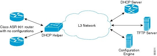
Zero-touch deployment feature gives the router the ability to retrieve its configuration file from the remote server during initial router deployment with no end-user intervention.

Figure 1. Zero-touch Deployment

The following steps provide an overview of events that take place during Cisco ASR 901 zero-touch deployment.

Procedure

Step 1

Connect the Cisco ASR 901 without any configurations to an upstream router.

Step 2

The Cisco ASR 901 auto-senses the management VLAN of the upstream router for IP connectivity by listening to the traffic it receives on the connected interface.

Step 3

The Cisco ASR 901 sends DHCP discover messages using the discovered VLAN tag. If the upstream router is not using a management VLAN, untagged DHCP discover messages are sent.

Step 4

The DHCP server responds with a DHCP offer.

Step 5

The Cisco ASR 901 sends a DHCP request message to the DHCP server. The DHCP server then sends the DHCP ACK message.

Note 
Step 6 and 7 are used only when Option 43 is not configured.
Step 6

The Cisco ASR 901 requests network-config file via TFTP.

Step 7

The TFTP server sends the Cisco ASR 901 a network-config file.

Step 8

The Cisco ASR 901 sends an HTTP request to the CNS-CE server.

Step 9

The CNS-CE server sends a configuration template to the Cisco ASR 901 .

Step 10

Publish success event.


Image Download

The following events take place when a CNS-enabled Cisco ASR 901 downloads a new image:

Procedure

Step 1

The CNS-CE server requests inventory (disk/flash info) from the ASR 901-DC.

Step 2

The ASR 901-DC. sends an inventory.

Step 3

The CNS-CE server sends an image location.

Step 4

The ASR 901-DC. sends a TFTP image request.

Step 5

The ASR 901-DC. downloads an image from the TFTP server.

Step 6

Refresh the CNS-CE server to check whether the image download is complete.

Step 7

Associate the .inv template in the CNS-CE server. Based on the boot variable, the Cisco ASR 901 reboots with the copied image.

Step 8

The CNS-CE server reboots the ASR 901-DC. router.


Configuring a DHCP Server

The Cisco ASR 901 requires a DHCP server for zero-touch deployment. Complete the following steps to configure a Cisco router as a DHCP server.

Procedure
  Command or Action Purpose
Step 1

enable

Example:

Router> enable

Enables privileged EXEC mode.

  • Enter your password if prompted.
Step 2

configure terminal

Example:

Router# configure terminal

Enters global configuration mode.

Step 3

ip dhcp excluded-address dhcp-server-ip-address

Example:

Router# ip dhcp excluded-address 30.30.1.6

Specifies to exclude IP address of the DHCP server.

Step 4

ip dhcp excluded-address ip-address subnet-mask

Example:

Router# ip dhcp excluded-address 30.30.1.20 30.30.1.255

Assigns IP addresses with an exception of 30.30.1.6, which is the IP address of the DHCP server.

Step 5

ip dhcp pool pool-name

Example:

Router# ip dhcp pabudhcp2

Specifies the DHCP pool name.

Step 6

network ip-address subnet-mask

Example:

Router# network 160.100.100.0 255.255.255.252

Specifies the IP address and subnet mask of the network.

Step 7

default-router ip-address

Example:

Router# default-router 30.30.1.6

Specifies the IP address of the default router.

Step 8

Do one of the following:

  • option 43 ascii string
  • option 150 ip <TFTP-server-ip-address>
Example:

Router# option 43 ascii 3A1D;A3;B161.100.100.2

Specifies Option 43 and a string value that has the CNS details, serial number of the hardware, and the code for CE IP address or Option 150 and the IP address of the TFTP server.

For more information on Option 43, see Constructing a DHCP Option 43 Message. Cisco ASR 901 Series Routers supports only few letter code options mentioned in this link.

Step 9

end

Example:

Router(config-if)# end

Exits configuration mode.

Configuring a TFTP Server

You need to set up a TFTP server to provide a bootstrap configuration to the Cisco ASR 901 routers when they boot using option 150.

Creating a Bootstrap Configuration

Create or download a file with the initial bootstrap configuration on the TFTP server. An example of the configuration file is shown below:


hostname test-router
!
cns trusted-server all-agents 30.30.1.20
cns event 30.30.1.20 11011 keepalive 60 3
cns config initial 30.30.1.20 80
cns config partial 30.30.1.20 80
cns id hostname
cns id hostname event
cns id hostname image
!
end

Enabling a TFTP Server on the Edge Router

The Cisco ASR 901 requires a TFTP server for zero-touch deployment while using option 150. The TFTP server is typically implemented on the carrier edge router. You can use the following global configuration commands to enable a TFTP server on the edge router that can send the initial configuration to the Cisco ASR 901 router.


tftp-server sup-bootflash:network-confg

After the Cisco ASR 901 boots with this configuration, it can connect to the CNS-CE server.

Configuring the Cisco Configuration Engine

The Cisco Configuration Engine (formerly known as the Cisco CNS Configuration Engine) allows you to remotely manage configurations and IOS software images on Cisco devices including the Cisco ASR 901 .

When the Cisco ASR 901 downloads the bootstrap configuration and connects to the Cisco Configuration Engine server, you can use the server to download a full configuration to the router. You can also use the CNS-CE server to complete any of the following tasks:

  • Manage configuration templates—The CNS-CE server can store and manage configuration templates.
  • Download a new image—You can use the CNS-CE server to load a new IOS image on a Cisco ASR 901 router.
  • Loading a new config—You can use the CNS-CE server to load a new configuration file on a Cisco ASR 901 router.
  • Enable identification—You can use a unique CNS agent ID to verify the identity of a host device prior to communication with the CNS-CE server.
  • Enable authentication—You can configure the CNS-CE server to require a unique password from the Cisco ASR 901 router as part of any communication handshake.
  • Enable encryption—You can enable Secure Socket Layer (SSL) encryption for the HTTP sessions between the CNS agent devices ( Cisco ASR 901 routers) and the CNS-CE server.

For instructions about how to use the CNS-CE server, see the Cisco Configuration Engine Installation & Configuration Guide at http://www.cisco.com/en/US/products/sw/netmgtsw/ps4617/tsd_products_support_series_home.html .

Configuration Examples

This section provides the following configuration examples:

Example: Configuring SNMP Support


!
snmp-server community xxxxx RO
snmp-server queue-length 100
snmp-server enable traps snmp linkdown linkup coldstart warmstart
snmp-server enable traps envmonsnmp-server host 10.20.30.40 version 2c
!

Example: Configuring Remote Network Management


cns trusted-server all-agents 30.30.1.20
cns event 30.30.1.20 11011 keepalive 60 3
cns config initial 30.30.1.20 80
cns config partial 30.30.1.20 80
cns id hostname
cns id hostname event
cns id hostname image
cns exec 80
logging buffered 20000
!
end

Example: Configuring a DHCP Server


ip dhcp excluded-address 30.30.1.6
ip dhcp excluded-address 30.30.1.20 30.30.1.255
!
ip dhcp pool asrdhcp
network 30.30.1.0 255.255.255.0
default-router 30.30.1.6
Option 43 ascii 3A1D;A3;B161.100.100.2
!
end

Example: Zero-touch Deployment

The following configuration example sets the Cisco ASR 901 to boot using configurations stored on a CNS–CE server with the IP address 30.30.1.20.


Note

This section provides partial configurations intended to demonstrate a specific feature.

hostname 901
!
cns trusted-server all-agents 30.30.1.20
cns event 30.30.1.20 11011 keepalive 60 3
cns config initial 30.30.1.20 80
cns config partial 30.30.1.20 80
cns id hostname
cns id hostname event
cns id hostname image
!
end

External Alarm Port Monitoring

The Cisco ASR 901 Series Routers supports an external alarm port (RJ45 connector) that serves four external dry-contact alarm inputs. You can connect up to four alarm inputs from external devices, such as a door, a temperature gauge, or a fire alarm, to the alarm input port on the front panel of the router. You can use the IOS command to set the alarm severity to minor, major, or critical. An alarm generates a system message.

The alarm setting is open or closed.

  • Open means that the normal condition has current flowing through the contact (referred to as normally closed contact). The alarm is generated when the current stops.

  • Closed means that no current flows through the contact (referred to as normally open contact). The alarm is generated when the current flows.

The alarm status is polled every second to check if there are any changes in the alarm state (based on the user configuration).


Note

External alarm port monitoring is disabled by default. CISCO-ENTITY-ALARM-MIB (Oid: 1.3.6.1.4.1.9.9.138: ceAlarmAsserted trap OID -- 1.3.6.1.4.1.9.9.138.2.0.1 and ceAlarmCleared trap OID -- 1.3.6.1.4.1.9.9.138.2.0.2 ) is used for Alarms.

Enabling Alarms

Procedure

  Command or Action Purpose
Step 1

enable

Example:

Router> enable

Enables privileged EXEC mode.

  • Enter your password if prompted.
Step 2

configure terminal

Example:

Router# configure terminal

Enters global configuration mode.

Step 3

alarm-contact contact-number description description-string

Example:

Router(config)# alarm-contact 1 description doorsensor

Configures a description for the alarm contact number.

  • The contact-number can be from 1 to 4.

  • The description string can be up to 48 alphanumeric characters in length and is included in any generated system messages.

Note 
To disable this configuration, use the no form of the command.
Step 4

alarm-contact { contact-number | all {severity{critical| major| minor}}

Example:

Router(config)# alarm-contact 2 severity major
Configure the trigger and severity for an alarm contact number or for all contact numbers.
  • Enter a contact number (1 to 4) or specify that you are configuring all alarms.

  • For severity, enter critical, major, or minor. If you do not configure a severity, the default is minor.

Note 

To disable this configuration, use the no form of the command.

Step 5

alarm-contact { contact-number | all { trigger {closed| open}}

Example:

Router(config)# alarm-contact 2 trigger closed
Configure the trigger for an alarm contact number or for all contact numbers.
  • For trigger, enter open or closed. If you do not configure a trigger, the alarm is triggered when the circuit is closed.

Note 

To disable this configuration, use the no form of the command.

Step 6

end

Example:

Router(config)# end

Returns to privileged EXEC mode.

Enabling Syslogs

Procedure

  Command or Action Purpose
Step 1

enable

Example:

Router> enable

Enables privileged EXEC mode.

  • Enter your password if prompted.
Step 2

configure terminal

Example:

Router# configure terminal

Enters global configuration mode.

Step 3

logging alarm severity

Example:

Router(config)# logging alarm informational

Enables the system to send alarm messages to logging devices and to configure the alarm severity threshold.

Step 4

logging host ip-address

Example:

Router(config)# logging host syslogServerIp

Logs system messages and debug output to a remote host.

Step 5

ip route dest-ip-address subnet-mask default-gateway

Example:

Router(config)# ip route 7.0.0.221 255.255.255.255 7.47.0.1

Configure the static routes.

Step 6

end

Example:

Router(config)# end

Returns to privileged EXEC mode.

Enabling SNMP Traps

Procedure

  Command or Action Purpose
Step 1

enable

Example:

Router> enable

Enables privileged EXEC mode.

  • Enter your password if prompted.
Step 2

configure terminal

Example:

Router# configure terminal

Enters global configuration mode.

Step 3

snmp-server manager

Example:

Router(config)# snmp-server manager

Starts the Simple Network Management Protocol (SNMP) manager process.

Step 4

snmp-server community string rw

Example:

Router(config)# snmp-server community public rw

Configures the community access string to permit access to the SNMP.

Step 5

snmp-server enable traps alarms notification-option

Example:

Router(config)# snmp-server enable traps alarms informational

Enables the traps related to alarms.

  • Severity - 1 is a critical event that affects the service condition.

  • Severity - 2 is a major event that requires immediate attention.

  • Severity - 3 is a minor event to indicate warning conditions.

  • Severity - 4 is meant for informational notifications.

Step 6

snmp-server host host-name ip-address version 2c public udp-port port notification-type

Example:

Router(config)# snmp-server host server ip version 2c public udp-port port num

Specifies the recipient of a SNMP notification operation.

Step 7

ip route dest-ip-address subnet-mask default-gateway

Example:

Router(config)# ip route 7.0.0.221 255.255.255.255 7.47.0.1

Configure the static routes.

Verifying Alarm Configuration

To verify the alarm configuration, use the show commands as shown in the examples below:


Router#  show environment alarm-contact

ALARM CONTACT 1
   Status:      not asserted
   Description: test_1
   Severity:    critical
   Trigger:     open
ALARM CONTACT 2
   Status:      not asserted
   Description: door sensor
   Severity:    major
   Trigger:     closed
ALARM CONTACT 3
   Status:      not asserted
   Description: flood sensor
   Severity:    critical
   Trigger:     closed
ALARM CONTACT 4
   Status:      not asserted
   Description: 
   Severity:    critical
   Trigger:     closed


Router#  show running-config | include alarm

alarm-contact 1 description AC Fail
alarm-contact 1 severity critical
alarm-contact 1 trigger closed
alarm-contact 2 description DC Fail
alarm-contact 2 trigger closed
alarm-contact 3 description Junk 3
alarm-contact 3 severity major
alarm-contact 3 trigger closed
alarm-contact 4 description Test 4
alarm-contact 4 severity critical
alarm-contact 4 trigger closed


Router#   show facility-alarm status

Source                 Time                 Severity         Description [Index]
------                ------               --------         -------------------
AC Fail              Jul 22 2014 18:23:45    CRITICAL       AC Fail [0]
DC Fail              Jul 22 2014 18:23:45    MINOR          DC Fail [1]
Junk 3               Jul 22 2014 18:23:45    MAJOR          Junk 3 [2]
Test 4               Jul 22 2014 18:23:46    CRITICAL       Test 4 [3]


Router#   show environment all | b Alarms

External Alarms:
ALARM CONTACT 1 is not asserted
ALARM CONTACT 2 is not asserted
ALARM CONTACT 3 is not asserted
ALARM CONTACT 4 is not asserted 

Where to Go Next

For additional information on monitoring and managing the Cisco ASR 901 router, see the documentation listed in the Additional References section.

Additional References

The following sections provide references related to LLDP feature.

Related Documents

Related Topic

Document Title

Cisco IOS commands

Cisco IOS Master Commands List, All Releases

Cisco ASR 901 Command Reference

Cisco ASR 901 Series Aggregation Services Router Command Reference

Cisco IOS Interface and Hardware Component Commands

Cisco IOS Interface and Hardware Component Command Reference

Standards

Standard

Title

None

MIBs

MIB

MIBs Link

None

To locate and download MIBs for selected platforms, Cisco software releases, and feature sets, use Cisco MIB Locator found at the following URL:

http://www.cisco.com/c/en/us/td/docs/wireless/asr_901/mib/reference/asr_mib.html

RFCs

RFC

Title

No new or modified RFCs are supported by this feature, and support for existing RFCs has not been modified by this feature.

Technical Assistance

Description

Link

The Cisco Support and Documentation website provides online resources to download documentation, software, and tools. Use these resources to install and configure the software and to troubleshoot and resolve technical issues with Cisco products and technologies. Access to most tools on the Cisco Support and Documentation website requires a Cisco.com user ID and password.

http://www.cisco.com/cisco/web/support/index.html

Feature Information for Monitoring and Managing the Cisco ASR 901 Router

Table 1 lists the release history for this feature and provides links to specific configuration information.

Use Cisco Feature Navigator to find information about platform support and software image support. Cisco Feature Navigator enables you to determine which software images support a specific software release, feature set, or platform. To access Cisco Feature Navigator, go to http://www.cisco.com/go/cfn . An account on Cisco.com is not required.


Note

Table 1 lists only the software release that introduced support for a given feature in a given software release train. Unless noted otherwise, subsequent releases of that software release train also support that feature.
Table 1. Feature Information for Monitoring and Managing the Cisco ASR 901 Router

Feature Name

Releases

Feature Information

Monitoring and Managing the Cisco ASR 901 Router

15.2(2)SNI

The following sections provide information about this feature:

Dry Contact Alarm Port

15.5(1)S

This feature was introduced on the Cisco ASR 901 Series Routers.