IP Security

This feature module describes how to configure the Internet Key Exchange (IKE) protocol for basic IP Security (IPsec) Virtual Private Networks (VPNs). IKE is a key management protocol standard that is used in conjunction with the IPsec standard. IPsec is an IP security feature that provides robust authentication and encryption of IP packets.

Prerequisites for IP Security

  • Although the Cisco ASR 901 Router supports the IPsec feature, it is supported only on the A901-6CZ-FS-D and A901-6CZ-FS-A PIDs.

  • For the IPsec and NAT/PAT to work on the ASR 901S router a physical loopback connection is required from the management port to any available Gigabit port before issuing the following command in configuration mode:

    platform mgmt loopback interface GigabitEthernet0/4.

    In this case, the physical connection is between the management port and Gigabit port 0/4.
Restrictions for IP Security

  • This feature is available only on the new software image named asr901sec-universalk9.mz. (This feature is not available on the standalone software image named asr901-universalk9.mz. If you use asr901sec-universalk9.mz in an unsupported Cisco ASR 901 PID, the router issues a warning message and loads the software with only basic features.)

  • Policy-based VPNs are not supported.
  • Only the tunnel mode is supported, and only one tunnel is supported.

The following features are not supported:

  • Authentication Header (AH) Hash Message Authentication Code (HMAC) with SHA512.
  • QoS on tunnel interface.
  • Combination of ESP as encryption and AH as hashing algorithm.
  • Extensible Authentication Protocol (EAP) with Message Digest 5 (MD5).
  • Low performance of non-UDP or TCP packets for IPsec.
  • PAT support for port channel.
  • Routing protocols, other than OSPF.
  • IPsec MIB.
  • Encapsulation of Security Payloads (ESP) with Null option.

Information About IP Security

The following features are supported on the Cisco ASR 901 Routers (A901-6CZ-FS-D and A901-6CZ-FS-A) from Cisco IOS Release 15.4(2)S onwards.

Advanced Encryption Standard

Advanced Encryption Standard (AES) is a cryptographic algorithm that protects sensitive, unclassified information. AES offers a large key size and supports variable key lengths—the algorithm can specify a 128-bit key (the default), a 192-bit key, or a 256-bit key.

For more information on AES, see the document at: http://www.cisco.com/c/en/us/td/docs/ios/ios_xe/sec_secure_connectivity/configuration/guide/xe_3s/sec_secure_connectivity_xe_3s_book/sec_key_exch_ipsec_xe.html

IKE Modes

IKE has two phases of key negotiation: phase 1 and phase 2. Phase 1 negotiates a security association (a key) between two IKE peers. The key negotiated in phase 1 enables IKE peers to communicate securely in phase 2. During phase 2 negotiation, IKE establishes keys (security associations) for other applications, such as IPsec.

Phase 1 negotiation can occur using main mode or aggressive mode. The main mode protects all information during the negotiation; this means that no information is available to a potential attacker. When main mode is used, the identities of the two IKE peers are hidden. Although this mode of operation is very secure, it is relatively costly in terms of the time it takes to complete the negotiation. Aggressive mode takes less time to negotiate keys between peers; however, it gives up some of the security provided by main mode negotiation. For example, the identities of the two parties trying to establish a security association are exposed to an eavesdropper.

The two modes serve different purposes and have different strengths. The main mode is slower than the aggressive mode, but the main mode is more secure and more flexible because it can offer an IKE peer more security proposals than the aggressive mode.

For more information on IKE modes, see the Configuring Internet Key Exchange for IPSec VPNs document at: http://www.cisco.com/en/US/docs/ios/ios_xe/sec_secure_connectivity/configuration/guide/sec_key_exch_ipsec_xe.html

Supported Components

The following components are supported as part of the IPsec feature:

  • IPsec in tunnel mode

  • Route-based IP security tunnels

  • IKEv2 support - in addition to IKEv1

  • Periodic dead peer detection (DPD)

  • IKE main mode (including 3 two-way exchanges)

  • Pre-Shared Key Exchange mechanism—DH group 1, 2, 5, 14, 15, 16, 19, 20, 21, 24

  • Encapsulation Security Payload (ESP) support

  • Encryption algorithms—AES (128,192,256), DES, and 3DES

  • Authentication algorithms—MD5, SHA-1, and SHA-2

  • IP security tunneling for CPU generated traffic for in-band traffic

  • IP security tunneling for Layer 3 forwarded traffic

  • Static routes

  • Coexistence with Layer 2 traffic

  • Coexistence with IP multicast

  • ToS bytes preservation after encryption and decryption.

  • NAT Traversal

For more information on IPsec see the documents listed in the “Additional References” section.

Configuring IP Security

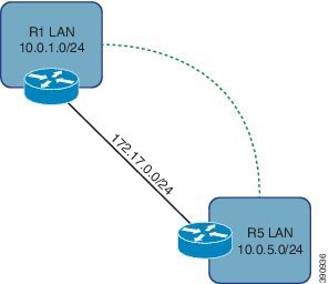
The following topology is used for the configurations listed in this document.

Figure 1. Route-based VPN

Creating a Preshared Key

A preshared key is a secret key previously shared between two routers, using a secure channel, before the key can be used. The key does not require the use of a certificate authority (CA), and is easier to set up in a small network with fewer than ten nodes.

Based on the topology listed above (Route-based IPsec), create a keyring and key for R1. Use the same keyring and key on R5. To create a preshared key, complete the following steps:

Procedure

  Command or Action Purpose
Step 1

enable

Example:

Router> enable

Enables privileged EXEC mode.

  • Enter your password if prompted.
Step 2

configure terminal

Example:

Router# configure terminal

Enters global configuration mode.

Step 3

crypto keyring keyring-name

Example:

Router(config)# crypto keyring VPN

Defines a crypto keyring to be used during IKE authentication.

  • keyring-name—Name of the crypto keyring.
Step 4

pre-shared-key address address key key

Example:

Router(config-keyring)# pre-shared-key address 172.17.0.5 key AnotherSecretKey

Defines a preshared key to be used for IKE authentication.

  • address—IP address of the remote peer.
  • key—Name of the secret key.

Creating an ISAKMP Policy

An Internet Security Association and Key Management Protocol (ISAKMP) policy provides configuration of the security and encryption parameters used for the security parameters of the ISAKMP communication channel, such as hashing, encryption, and key length.

To create an ISAKMP policy, complete the following steps:

Procedure

  Command or Action Purpose
Step 1

enable

Example:

Router> enable

Enables privileged EXEC mode.

  • Enter your password if prompted.
Step 2

configure terminal

Example:

Router# configure terminal

Enters global configuration mode.

Step 3

crypto isakmp policy priority

Example:

Router(config)# crypto isakmp policy 10

Defines an IKE policy and enters config-isakmp configuration mode.

  • priority—IKE policy priority.
Step 4

encryption aes 256

Example:

Router(config-isakmp)# encryption aes 256

Specifies the encryption algorithm within an IKE policy.

Step 5

authentication pre-share

Example:

Router(config-isakmp)# authentication pre-share

Specifies the authentication method within an IKE policy.

Step 6

group 5

Example:

Router(config-isakmp)# group 5

Specifies one or more Diffie-Hellman (DH) group identifiers for use in an IKE policy.

Step 7

hash md5

Example:

Router(config-isakmp)# hash md5

Specifies the hashing algorithm within IKE policy.

Creating an ISAKMP Profile

The ISAKMP profile is an enhancement to ISAKMP configuration. It enables modularity of ISAKMP configuration. The ISAKMP profile is required on both routers (R1 and R5. See the figure in Configuring IPsec section.) to match the peer IP address to the preshared key keyring.

To create an ISAKMP profile, complete the following steps:

Procedure

  Command or Action Purpose
Step 1

enable

Example:

Router> enable

Enables privileged EXEC mode.

  • Enter your password if prompted.
Step 2

configure terminal

Example:

Router# configure terminal

Enters global configuration mode.

Step 3

crypto isakmp profile profile-name

Example:

Router(config)# crypto isakmp profile R1_to_R5

Defines an ISAKMP profile.

  • profile-name—Name of the user profile.
Step 4

keyring keyring-name

Example:

Router(config-isa-prof)# keyring VPN

Configures a keyring with an ISAKMP profile.

  • keyring-name—Name of the keyring, which must match the keyring name that was defined in the global configuration.
Step 5

match identity address ip-address

Example:

Router(config-isa-prof)# match identity address 172.17.0.5 255.255.255.255

Matches an identity from a peer in an ISAKMP profile .

  • ip-address—The IP address to match.
Step 6

exit

Example:

Router(config-isa-prof)# exit 

Enters ISAKMP profile configuration mode.

Note 
Repeat step 3 to 6 to configure the ISAKMP profile on the second router. Remember to use a different profile-name and ip-address.

Defining an IPsec Transform Set

An IPsec transform set is an acceptable combination of security protocols and algorithms. You should define an IPsec transform set on both the routers (R1 and R5. See the figure in Configuring IPsec section.).

To define an IPsec transform set, complete the following steps:

Procedure

  Command or Action Purpose
Step 1

enable

Example:

Router> enable

Enables privileged EXEC mode.

  • Enter your password if prompted.
Step 2

configure terminal

Example:

Router# configure terminal

Enters global configuration mode.

Step 3

crypto ipsec transform-set transform-set-name transform1 transform2

Example:

Router(config)# crypto ipsec transform-set ESP-AES256-SHA1 esp-aes 256 esp-sha-hmac

Defines a transform set, an acceptable combination of security protocols and algorithms.

  • transform-set-name—Name of the transform set to create (or modify.
  • transform1/transform2—Type of transform set. You can specify up to four transforms, one AH, one ESP encryption, one ESP authentication, and one compression. These transforms define the IPsec security protocols and algorithms.
Step 4

exit

Example:

Router(config)# exit

Exits global configuration mode.

Creating an IPsec Profile

An IPsec profile serves as a wrapper around one or more transform sets and other parameters used in the construction of an IPsec SA. You should create IPsec profiles on both the routers (R1 and R5. See the figure in Configuring IPsec section.).

To create an IPsec profile, complete the following steps:

Procedure

  Command or Action Purpose
Step 1

enable

Example:

Router> enable

Enables privileged EXEC mode.

  • Enter your password if prompted.
Step 2

configure terminal

Example:

Router# configure terminal

Enters global configuration mode.

Step 3

crypto ipsec profile profile-name

Example:

Router(config)# crypto ipsec profile Routed_VPN

Defines the IPsec parameters that are to be used for IPsec encryption between two IPsec routers (See the figure in Configuring IPsec section) and enters IPsec profile configuration mode.

  • profile-name—Name of the crypto ipsec profile.
Step 4

set transform-set transform-set-name

Example:

Router(ipsec-profile)# set transform-set ESP-AES256-SHA1

Attaches the desired transform set to IPsec profile.

Step 5

set isakmp-profile profile-name

Example:

Router(ipsec-profile)# set isakmp-profile R1_to_R5

Attaches the desired ISAKMP profile to IPsec profile.

Step 6

exit

Example:

Router(ipsec-profile)# exit

Exits ipsec profile configuration mode and enters global configuration mode.

Creating a VPN Tunnel Interface

A routed tunnel interface on both the routers ((R1 and R5. See the figure in Configuring IPsec section.) acts as logical VPN edge. The tunnel interfaces serve to encapsulate or encrypt egress traffic and decapsulate or decrypt ingress traffic. You should create tunnels on both the routers.

To create a VPN tunnel interface, complete the following steps:

Procedure

  Command or Action Purpose
Step 1

enable

Example:

Router> enable

Enables privileged EXEC mode.

  • Enter your password if prompted.
Step 2

configure terminal

Example:

Router# configure terminal

Enters global configuration mode.

Step 3

interface type number

Example:

Router(config)# interface Tunnel0

Specifies an interface type and number, and enters interface configuration mode.

Step 4

ip address primary-ip-address seconary-ip-address

Example:

Router(config-if)# ip address 192.168.0.1 255.255.255.252

Matches an identity from a peer in an ISAKMP profile.

  • ip-address—The ip-address to match.
Step 5

tunnel source ip-address

Example:

Router(config-if)# tunnel source 172.17.0.1

Sets the source address for a tunnel interface.

  • ip-address—Source IP address of the packets in the tunnel.
Step 6

tunnel destination ip-address

Example:

Router(config-if)# tunnel destination 172.17.0.5

Specifies the destination for a tunnel interface.

  • ip-address—IP address of the host destination.
Step 7

tunnel mode ipsec ipv4

Example:

Router(config-if)# tunnel mode ipsec ipv4

Sets the encapsulation mode for a tunnel interface.

Step 8

tunnel protection ipsec profile name

Example:

Router(config-if)# tunnel protection ipsec profile Routed_VPN

Associates a tunnel interface with an IPsec profile.

  • name—Name of the IPsec profile.

Configuring Static Routing

Route-based VPNs cannot automatically discover remote networks that are reachable over the VPN. To communicate this information, you should configure a static route.

To create a static route, complete the following steps:

Procedure

  Command or Action Purpose
Step 1

enable

Example:

Router> enable

Enables privileged EXEC mode.

  • Enter your password if prompted.
Step 2

configure terminal

Example:

Router# configure terminal

Enters global configuration mode.

Step 3

ip route ip-address mask interface number

Example:

Router(config)# ip route 10.0.5.0 255.255.255.0 tunnel0

Configures a static route on the first router (R1 and R5. See the figure in Configuring IPsec section.).

  • ip-address—IP address of the host destination.
  • mask—Prefix mask for the destination.
  • number—Network interface type and interface number.
Step 4

ip route ip-address mask interface number

Example:

Router(config)# ip route 10.0.1.0 255.255.255.0 tunnel0

Configures a static route on the second router.

Step 5

exit

Example:

Router(config-if)# exit

Exits interface configuration mode and enters global configuration mode.

Verifying Static Routing

To display the contents of a routing table, use the show ip route commands, as shown in the following example:

Router# show ip route

Codes: C - connected, S - static, R - RIP, M - mobile, B - BGP
       D - EIGRP, EX - EIGRP external, O - OSPF, IA - OSPF inter area 
       N1 - OSPF NSSA external type 1, N2 - OSPF NSSA external type 2
       E1 - OSPF external type 1, E2 - OSPF external type 2
       i - IS-IS, su - IS-IS summary, L1 - IS-IS level-1, L2 - IS-IS level-2
       ia - IS-IS inter area, * - candidate default, U - per-user static route
       o - ODR, P - periodic downloaded static route

Gateway of last resort is not set

172.17.0.0/24 is subnetted, 1 subnets
C       172.17.0.0 is directly connected, GigabitEthernet0/1
     172.16.0.0/24 is subnetted, 1 subnets
C       172.16.0.0 is directly connected, GigabitEthernet0/0
     10.0.0.0/24 is subnetted, 2 subnets
S       10.0.3.0 [10/0] via 172.16.0.3
C       10.0.1.0 is directly connected, Loopback1
     192.168.0.0/30 is subnetted, 1 subnets
C       192.168.0.0 is directly connected, Tunnel0
10.0.0.0/24 is subnetted, 1 subnets
S        10.0.5.0 is directly connected, Tunnel0

To display current IKE SAs, use the show crypto isakmp sa command, as shown in the following example:

Router# show crypto isakmp sa

IPv4 Crypto ISAKMP SA
dst             src             state          conn-id status
172.17.0.5      172.17.0.1      QM_IDLE           4004 ACTIVE

Enabling Dynamic Routing

Route-based VPNs cannot automatically discover remote networks that are reachable over the VPN. To communicate this information, static routers (as mentioned in the section, Configuring Static Routing) or routing protocols can be configured. OSPF is the only protocol currently supported VPNs.

OSPF should be enabled for both the internal LAN interface (which a loopback pretending to be a /24 network) and the tunnel interface. An OSPF adjacency should form between R1 and R5 over the 192.168.0.0/30 network, inside the VPN.

To create a VPN tunnel interface, complete the following steps.

Procedure

  Command or Action Purpose
Step 1

enable

Example:

Router> enable

Enables privileged EXEC mode.

  • Enter your password if prompted.
Step 2

configure terminal

Example:

Router# configure terminal

Enters global configuration mode.

Step 3

interface type number

Example:

Router(config)# interface Tunnel0

Specifies an interface type and number, and enters interface configuration mode.

Step 4

ip ospf process-id areaarea-id

Example:

Router(config-if)# ip ospf 1 area 0

Enables Open Shortest Path First version 2 (OSPFv2) on an interface.

  • process-id—IP address of the host destination.
  • area-id—A decimal value in the range from 0 to 4294967295, or an IP address.
Step 5

ip ospf mtu-ignore

Example:

Router(config-if)# ip ospf mtu-ignore

Disables OSPF MTU mismatch detection on receiving database descriptor (DBD) packets.

Step 6

exit

Example:

Router(config-if)# exit

Exits interface configuration mode and enters global configuration mode.

Step 7

interface type number

Example:

Router(config)# interface Loopback0

Specifies an interface type and number, and enters interface configuration mode.

Step 8

router ospf process-id area area-id

Example:

Router(config-if)# ip ospf 1 area 0

Enables OSPFv2 on an interface.

Step 9

exit

Example:

Router(config-if)# exit

Exits interface configuration mode and enters global configuration mode.

Verifying Dynamic Routing

R1 and R5 should learn the LAN prefixes of each other through OSPF, and both networks should be immediately reachable through the VPN tunnel.

R1# show ip route
Codes: C - connected, S - static, R - RIP, M - mobile, B - BGP
       D - EIGRP, EX - EIGRP external, O - OSPF, IA - OSPF inter area 
       N1 - OSPF NSSA external type 1, N2 - OSPF NSSA external type 2
       E1 - OSPF external type 1, E2 - OSPF external type 2
       i - IS-IS, su - IS-IS summary, L1 - IS-IS level-1, L2 - IS-IS level-2
       ia - IS-IS inter area, * - candidate default, U - per-user static route
       o - ODR, P - periodic downloaded static route

Gateway of last resort is not set

172.17.0.0/24 is subnetted, 1 subnets
C       172.17.0.0 is directly connected, GigabitEthernet0/1
     172.16.0.0/24 is subnetted, 1 subnets
C       172.16.0.0 is directly connected, GigabitEthernet0/0
     10.0.0.0/8 is variably subnetted, 3 subnets, 2 masks
S       10.0.3.0/24 [10/0] via 172.16.0.3
C       10.0.1.0/24 is directly connected, Loopback1
O       10.0.5.1/32 [110/1001] via 192.168.0.2, 00:01:29, Tunnel0
     192.168.0.0/30 is subnetted, 1 subnets
C       192.168.0.0 is directly connected, Tunnel0

R1# ping 10.0.5.1 source 10.0.1.1

Type escape sequence to abort.
Sending 5, 100-byte ICMP Echos to 10.0.5.1, timeout is 2 seconds:
Packet sent with a source address of 10.0.1.1 
!!!!!
Success rate is 100 percent (5/5), round-trip min/avg/max = 1/3/4 ms

Configuration Examples for IP Security

Example: Creating a Preshared Key

Router1

The following is a sample configuration for creating a preshared key and sharing it on two routers:

!
crypto keyring VPN 
  pre-shared-key address 172.17.0.5 key AnotherSecretKey
!

!
crypto keyring VPN
  pre-shared-key address 172.17.0.1 key AnotherSecretKey
!

Example: Creating an ISAKMP Policy

The following is a sample configuration of an ISAKMP policy:


!
crypto isakmp policy 10
 hash md5
 encr aes 256
 authentication pre-share
 group 5
!

Example: Creating an ISAKMP Profile

Router1

The following is a sample configuration of an ISAKMP profile:


!
crypto isakmp profile R1_to_R5
   keyring VPN
   match identity address 172.17.0.5 255.255.255.255 
!

!
crypto isakmp profile R5_to_R1
   keyring VPN
   match identity address 172.17.0.1 255.255.255.255
!

Example: Defining an IPsec Transform Set

The following is a sample configuration of an IPsec transform set:


!
crypto ipsec transform-set ESP-AES256-SHA1 esp-aes 256 esp-sha-hmac
!

Example: Creating an IPsec Profile

The following is a sample configuration of an IPsec profile:


!
crypto ipsec profile Routed_VPN
 set isakmp-profile R1_to_R5
 set transform-set ESP-AES256-SHA1 
!

Example: Creating a VPN Tunnel Interface

Router1

The following is a sample configuration of a VPN tunnel interface:


!
interface Tunnel0
 ip address 192.168.0.1 255.255.255.252
 tunnel source 172.17.0.1
 tunnel destination 172.17.0.5
 tunnel mode ipsec ipv4
 tunnel protection ipsec profile Routed_VPN
!

!
interface Tunnel0
 ip address 192.168.0.2 255.255.255.252
 tunnel source 172.17.0.5
 tunnel destination 172.17.0.1
 tunnel mode ipsec ipv4
 tunnel protection ipsec profile Routed_VPN
!

Example: Configuring Static Routing

Router1

The following is a sample configuration of static routing:


!
ip route 10.0.5.0 255.255.255.0 tunnel0
!


!
!
ip route 10.0.1.0 255.255.255.0 tunnel0
!
!

Example: Enabling Dynamic Routing

The following is a sample configuration of dynamic routing.


R1 and R5
router ospf 1
!
interface Loopback1
 ip ospf 1 area 0
!
interface Tunnel0
 ip ospf 1 area 0
 ip ospf mtu-ignore

NAT Traversal

The NAT Tranversal feature provides support for IP Security (IPsec) traffic to travel through Network Address Translation (NAT) or Port Address Translation (PAT) points in the network. This feature provides this support by addressing many known incompatibilities between NAT and IPsec.

Before the introduction of this feature, a standard IPsec virtual private network (VPN) tunnel would not work if there were one or more NAT or PAT points in the delivery path of the IPsec packet. This feature makes NAT IPsec-aware; thereby, allowing remote access users to build IPsec tunnels to home gateways.


Note

Security threats, as well as the cryptographic technologies to help protect against them, are constantly changing. For more information about the latest Cisco cryptographic recommendations, see the Next Generation Encryption (NGE) white paper.


Restrictions for NAT Traversal

NAT Traversal feature has the following restrictions:

  • NAT Traversal is only supported for IPv4.

  • NAT Traversal supports IPSec end to end connectivity.

  • NAT Traversal feature does not affect other feature functionality.

  • ASR 901S routers do not support volume-based rekey. For interoperability deployments, vendor IPsec peer should also disable the volume-based rekey to prevent IPsec tunnel to flap.

Information About NAT Traversal

Feature Design of IPsec NAT Traversal

The IPsec NAT Transparency feature provides support for IPsec traffic to travel through NAT or PAT points in the network by encapsulating IPsec packets in a User Datagram Protocol (UDP) wrapper, which allows the packets to travel across NAT devices. The following sections define the details of NAT traversal:

IKE Phase 1 Negotiation NAT Detection

During Internet Key Exchange (IKE) phase 1 negotiation, two types of NAT detection occur before IKE Quick Mode begins--NAT support and NAT existence along the network path.

To detect NAT support, you should exchange the vendor identification (ID) string with the remote peer. During Main Mode (MM) 1 and MM 2 of IKE phase 1, the remote peer sends a vendor ID string payload to its peer to indicate that this version supports NAT traversal. Thereafter, NAT existence along the network path can be determined.

Detecting whether NAT exists along the network path allows you to find any NAT device between two peers and the exact location of NAT. A NAT device can translate the private IP address and port to public value (or from public to private). This translation changes the IP address and port if the packet goes through the device. To detect whether a NAT device exists along the network path, the peers should send a payload with hashes of the IP address and port of both the source and destination address from each end. If both ends calculate the hashes and the hashes match, each peer knows that a NAT device does not exist on the network path between them. If the hashes do not match (that is, someone translated the address or port), then each peer needs to perform NAT traversal to get the IPsec packet through the network.

The hashes are sent as a series of NAT discovery (NAT-D) payloads. Each payload contains one hash. If multiple hashes exist, multiple NAT-D payloads are sent. In most environments, there are only two NAT-D payloads--one for the source address and port and one for the destination address and port. The destination NAT-D payload is sent first, followed by the source NAT-D payload, which implies that the receiver should expect to process the local NAT-D payload first and the remote NAT-D payload second. The NAT-D payloads are included in the third and fourth messages in Main Mode and in the second and third messages in Aggressive Mode (AM).

IKE Phase 2 Negotiation NAT Traversal Decision

While IKE phase 1 detects NAT support and NAT existence along the network path, IKE phase 2 decides whether or not the peers at both ends will use NAT traversal. Quick Mode (QM) security association (SA) payload in QM1 and QM2 is used to for NAT traversal negotiation.

Because the NAT device changes the IP address and port number, incompatibilities between NAT and IPsec can be created. Thus, exchanging the original source address bypasses any incompatibilities.

UDP Encapsulation of IPsec Packets for NAT Traversal

In addition to allowing IPsec packets to traverse across NAT devices, UDP encapsulation also addresses many incompatibility issues between IPsec and NAT and PAT. The resolved issues are as follows:

Incompatibility Between IPsec ESP and PAT--Resolved

If PAT finds a legislative IP address and port, it drops the Encapsulating Security Payload (ESP) packet. To prevent this scenario, UDP encapsulation is used to hide the ESP packet behind the UDP header. Thus, PAT treats and processes the ESP packet as a UDP packet.

Incompatibility Between Checksums and NAT--Resolved

In the new UDP header, the checksum value is always assigned to zero. This value prevents an intermediate device from validating the checksum against the packet checksum; thereby, resolving the TCP UDP checksum issue because NAT changes the IP source and destination addresses.

Incompatibility Between Fixed IKE Destination Ports and PAT--Resolved

PAT changes the port address in the new UDP header for translation and leaves the original payload unchanged.

To see how UDP encapsulation helps to send IPSec packets, see the figures below.

Figure 2. Standard IPsec Tunnel Through a NAT/PAT Point (No UDP Encapsulation)
Figure 3. IPsec Packet with UDP Encapsulation
UDP Encapsulated Process for Software Engines Transport Mode and Tunnel Mode ESP Encapsulation

After the IPsec packet is encrypted by a hardware accelerator or a software crypto engine, a UDP header and a non-ESP marker (which is 4 bytes in length) are inserted between the original IP header and ESP header. The total length, protocol, and checksum fields are changed to match this modification.

NAT Keepalives

NAT keepalives are enabled to keep the dynamic NAT mapping alive during a connection between two peers. NAT keepalives are UDP packets with an unencrypted payload of 1 byte. Although the current dead peer detection (DPD) implementation is similar to NAT keepalives, there is a slight difference: DPD is used to detect peer status, while NAT keepalives are sent if the IPsec entity did not send or receive the packet at a specified period of time in seconds--valid range is from 5 to 3600.

If NAT keepalives are enabled (through the crypto isamkp nat keepalive command), users should ensure that the idle value is shorter than the NAT mapping expiration time, which is 20 seconds.

How to Configure NAT and IPsec
Configuring NAT Traversal

NAT Traversal is a feature that is auto detected by VPN devices. There are no configuration steps for a router running Cisco IOS Release 12.2(13)T. If both VPN devices are NAT-T capable, NAT Traversal is auto detected and auto negotiated.

Disabling NAT Traversal

You may wish to disable NAT traversal if you already know that your network uses IPsec-awareness NAT (spi-matching scheme). To disable NAT traversal, use the following commands:

Procedure
  Command or Action Purpose
Step 1

enable

Example:

Router> enable

Enables higher privilege levels, such as privileged EXEC mode.

Enter your password if prompted.

Step 2

configure terminal

Example:

Router# configure terminal

Enters global configuration mode.

Step 3

no crypto ipsec nat-transparency udp-encapsulation

Example:

Router(config)# 
no crypto ipsec nat-transparency udp-encapsulation

Disables NAT traversal.

Configuring NAT Keepalives

To configure your router to send NAT keepalives, use the following commands:

Procedure
  Command or Action Purpose
Step 1

enable

Example:

Router> enable

Enables higher privilege levels, such as privileged EXEC mode.

Enter your password if prompted.

Step 2

configure terminal

Example:

Router# configure terminal

Enters global configuration mode.

Step 3

crypto isakmp nat keepalive seconds

Example:

Router(config)# 
crypto isakmp nat keepalive 20

Allows an IPsec node to send NAT keepalive packets.

  • seconds --The number of seconds between keepalive packets; range is from 5 to 3,600.

Note 

When the timer is modified, it is modified for every Internet Security Association Key Management Protocol (ISAKMP) security association (SA) when the keepalive for that SA is sent based on the existing timer.

Note 

A five-percent jitter mechanism value is applied to the timer to avoid security association rekey collisions. If there are many peer routers, and the timer is configured too low, then the router can experience high CPU usage.

Verifying IPsec Configuration

To verify your configuration, perform the following optional steps:

Procedure
  Command or Action Purpose
Step 1

enable

Example:

Router> enable

Enables higher privilege levels, such as privileged EXEC mode.

Enter your password if prompted.

Step 2

show crypto ipsec sa [map map-name | address | identity ] [detail

Example:

Router# show crypto ipsec sa

Displays the settings used by current SAs.

Configuration Examples for IPsec and NAT
NAT Keepalives Configuration Example

The following example shows how to enable NAT keepalives to be sent every 20 seconds:


crypto isakmp policy 1
  encryption aes
  authentication pre-share
  group 14
crypto isakmp key 1234 address 56.0.0.1
crypto isakmp nat keepalive 20
!
!
crypto ipsec transform-set t2 esp-aes esp-sha-hmac
!
crypto map test2 10 ipsec-isakmp
 set peer 56.0.0.1
 set transform-set t2
 match address 101

Additional References

The following sections provide references related to IP Security feature.

Standards

Table 1. Standard

Standard

Title

None

MIBs

MIB

MIBs Link

  • CISCO-IPSEC-FLOW-MONITOR-MIB
  • CISCO-IPSEC-MIB

To locate and download MIBs for selected platforms, Cisco IOS releases, and feature sets, use Cisco MIB Locator found at the following URL:

http://tools.cisco.com/ITDIT/MIBS/servlet/index

RFCs

RFC Title

None

Technical Assistance

Table 2. Technical Assistance

Description

Link

The Cisco Technical Support website contains thousands of pages of searchable technical content, including links to products, technologies, solutions, technical tips, and tools. Registered Cisco.com users can log in from this page to access even more content.

http://www.cisco.com/cisco/web/support/index.html

Feature Information for IP Security

The following table lists the features in this module and provides links to specific configuration information.

Use Cisco Feature Navigator to find information about platform support and software image support. Cisco Feature Navigator enables you to determine which software images support a specific software release, feature set, or platform. To access Cisco Feature Navigator, go to http://www.cisco.com/go/cfn. An account on Cisco.com is not required.


Note

The following table lists only the software release that introduced support for a given feature in a given software release train. Unless noted otherwise, subsequent releases of that software release train also support that feature.
Table 3. Feature Information for IP Security
Feature Name Releases Feature Information

IP Security

15.4(2)S

This feature was introduced on the Cisco ASR 901 Series Routers.

The following sections provide information about this feature: