|
Step 1
|
enable
|
Enables
privileged EXEC mode. Enter your password if prompted.
|
|
Step 2
|
configure
terminal
Router# configure terminal
|
Enters global
configuration mode.
|
|
Step 3
|
ethernet ring g8032
ring-name
Router(config)# ethernet ring g8032 ring1
|
Creates the
Ethernet ring and enters the Ethernet ring port configuration mode.
|
|
Step 4
|
port0 interface
type
number
Router(config-erp-ring)# port0 interface gigabitethernet 0/1
|
Connects port0
of the local node to the Ethernet ring and enters Ethernet ring protection
mode.
|
|
Step 5
|
monitor service instance
instance-id
Router(config-erp-ring-port)# monitor service instance 1
|
(Optional)
Assigns the Ethernet service instance to monitor the ring port (port0) and
detect ring failures.
If this
command is used, the service instance should be configured with CFM sessions.
In such a scenario, CFM session failures, if any, will be tracked as G.8032
link failures.
|
Note
|
We
recommend that you use this command in microwave links where signal degradation
will not be identified as physical link failures.
|
If this
command is not used, G.8032 will track only the physical link failures.
|
|
Step 6
|
exit
Router(config-erp-ring-port)# exit
|
Exits the
Ethernet ring port configuration mode.
|
|
Step 7
|
port1
{interface
type
number
|
none}
Router(config-erp-ring)# port1 interface gigabitethernet 0/1
|
Connects port1
of the local node to the Ethernet ring and enters the Ethernet ring protection
mode.
|
|
Step 8
|
monitor service instance
instance-id
Router(config-erp-ring-port)# monitor service instance 2
|
(Optional)
Assigns the Ethernet service instance to monitor the ring port (port1) and
detect ring failures.
If this
command is used, the service instance should be configured with CFM sessions.
In such a scenario, CFM session failures, if any, will be tracked as G.8032
link failures.
|
Note
|
We
recommend that you use this command in microwave links where signal degradation
will not be identified as physical link failures.
|
If this
command is not used, G.8032 will track only the physical link failures.
|
|
Step 9
|
exit
Router(config-erp-ring-port)# exit
|
Exits Ethernet
ring port configuration mode.
|
|
Step 10
|
exclusion-list vlan-ids
vlan-id
Router(config-erp-ring)# exclusion-list vlan-ids 2
|
(Optional)
Specifies VLANs that are unprotected (unblocked) by the Ethernet ring
protection mechanism.
If the command
is not used, VLANS that are not defined in the inclusion list in
16 will be
completely blocked for the traffic.
If the command
is used, VLANS that are not defined in the inclusion list and exclusion list
will be completely blocked for the traffic.
|
|
Step 11
|
open-ring
Router(config-erp-ring)# open-ring
|
(Optional)
Specifies the Ethernet ring as an open ring.
By default,
Ethernet ring is closed.
|
|
Step 12
|
instance
instance-id
Router(config-erp-ring)# instance 1
|
Configures the
Ethernet ring instance and enters the Ethernet ring instance configuration
mode.
|
|
Step 13
|
description
descriptive-name
Router(config-erp-inst)# description cisco_customer_instance
|
Specifies a
descriptive name for the Ethernet ring instance.
|
|
Step 14
|
profile
profile-name
Router(config-erp-inst)# profile profile1
|
Specifies the
profile associated with the Ethernet ring instance configured in
12.
|
|
Step 15
|
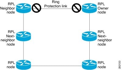
rpl
{port0 | port1 }
{
owner | neighbor | next-neighbor}
Router(config-erp-inst)# rpl port0 neighbor
|
Specifies the
Ethernet ring port on the local node as the RPL owner, neighbor, or next
neighbor.
|
|
Step 16
|
inclusion-list vlan-ids
vlan-id
Router(config-erp-inst)# inclusion-list vlan-ids 11
|
Specifies the
VLANs that are protected by the Ethernet ring protection mechanism.
|
|
Step 17
|
aps-channel
Router(config-erp-inst)# aps-channel
|
Enters the
Ethernet ring instance aps-channel configuration mode.
|
|
Step 18
|
level
level-value
Router(config-erp-inst-aps)# level 5
|
Specifies the
Automatic Protection Switching (APS) message level for the node on the Ethernet
ring.
All the nodes
in the Ethernet ring must be configured at the same level. The default level is
7.
|
|
Step 19
|
port0
service instance
instance-id
Router(config-erp-inst-aps)# port0 service instance 100
|
Associates APS
channel information with port0.
|
|
Step 20
|
port1
service instance
instance-id
Router(config-erp-inst-aps)# port1 service instance 100
|
Associates APS
channel information with port1.
|
|
Step 21
|
end
Router(config-erp-inst-aps)# end
|
Returns to
privileged EXEC mode.
|

 Feedback